How to cross the mouse with a compass, or again about Logitech

Good day to you, dear geeks and sympathizers!
In this publication, I want to share my way of overcoming the consequences of premature wear of the microswitch buttons on Logitech computer mice. As you know, there are many suggested ways to solve the double-click problem (or, more rarely, skip clicks) (physical, circuitry and even chemical methods are known to the general public), but none of them suggests excluding the most unreliable and inaccurate site microswitch. Here I will try to consistently outline the entire process of the difficult treatment of my Logitech MX1100 homeless tailless rodent.
The reason for starting the process was the ever-increasing cases of spontaneous double clicks. It would not have been difficult to find a replacement for this morally and technically outdated mouse if it were not for its plump back, so conveniently lying in my big
')
A radical solution: the microswitch should disappear, giving way to a more highly developed and reliable (contactless!) Device. So what will it be? Let's voice the main requirements: small size, ease of installation, low overall power consumption and operation at a supply voltage of 2.85 V (I measured this voltage at the output of the mouse power supply converter). Consider the individual types of devices and their disadvantages. Optocoupler - the consumption of significant current, the need for a separate power control circuit LED, the need for precise installation of the curtain. Touch (capacitive) sensor - expensive, the possibility of false positives, the inconvenience of use (you need to monitor the position of the finger). Inductive sensor - high power consumption, large size.
Finally, the favorite was identified: a magnetic field sensor, also known as a Hall sensor or a Hall sensor. The chip maker Allegro has a wonderful chip in the portfolio under the A3212ELHLT – T marking, characterized by
Output A3212 is organized on the principle of open drain, which makes it necessary to have an external resistor and an additional device that emulates a switching group of contacts. Why do you need it? The fact is that microswitches in these mice are polled dynamically and have a connection circuit to the microcontroller that is rather inconvenient for modifications. For this reason, it is much easier to provide switch emulation than to try to adapt an existing circuit to provide direct control over logic levels. A miniature solid-state switching relay MAX4624EUT-T in the SOT23-6 package was chosen for the emulator role. This chip consumes about 18 microwatts and is capable of operating at a supply voltage of 1.8 to 5.5 volts. The maximum resistance of the keys in the open state is 2 ohms at a supply voltage of 3 volts. This is a fairly low impedance for reliable operation of digital inputs and outputs of the chips.
As a result of
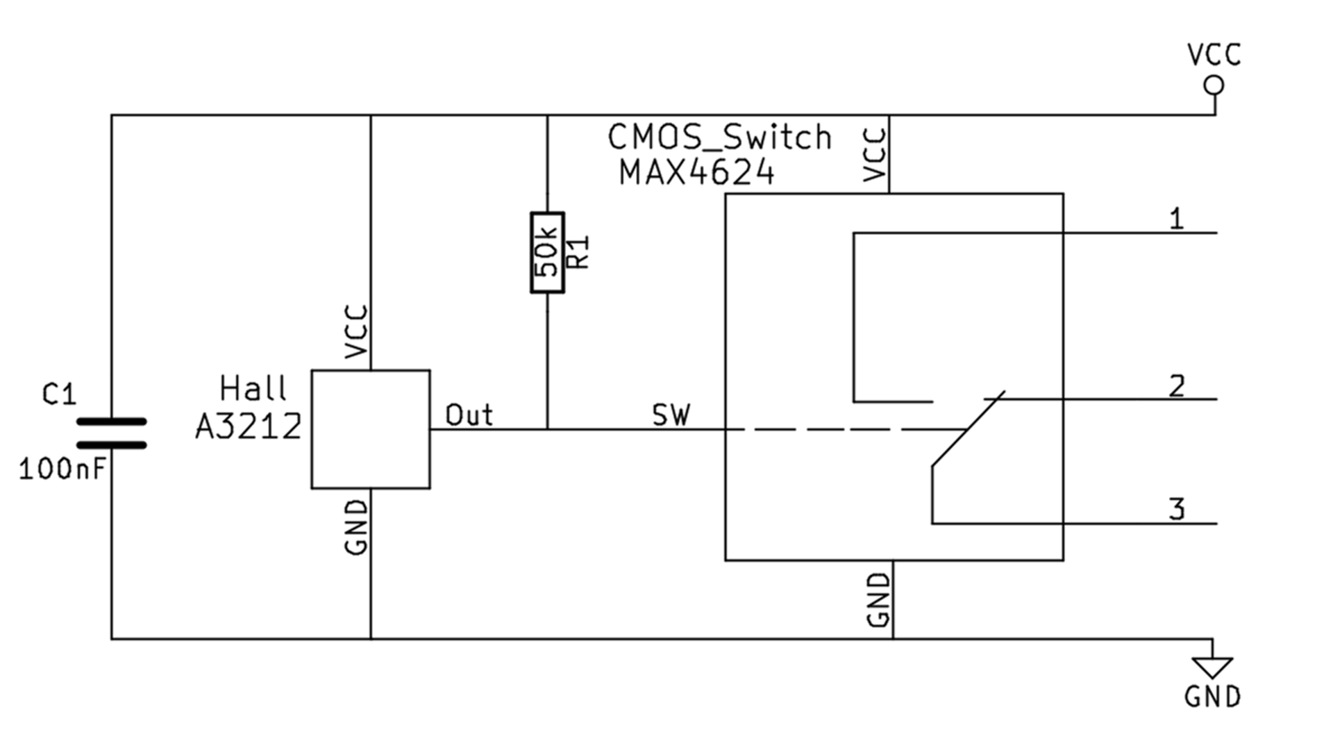
Here, VCC is 2.85 volts from the mouse power board, GND is the negative battery cable. Lines 1,2 and 3 are soldered to the corresponding contacts of the printed circuit board (directly to the microswitch legs). Installation is carried out with a thin insulated wire using SMD components. For example, the resistor size 0805 can be unsoldered directly on the legs of A3212, and the capacitor size 1206 can be glued on top of MAX4624. As it is usually said in amateur radio circles, a properly assembled circuit works right away and does not need any adjustment.
We use the cover of the microswitch as a housing-holder for the Hall sensor. You just need to expand the hole in which there was a white plastic pusher of the moving contact, and glue the sensor in there with epoxy resin. With this we will ensure reliable fixation and correct positioning of the sensor under the lever of the mouse button.
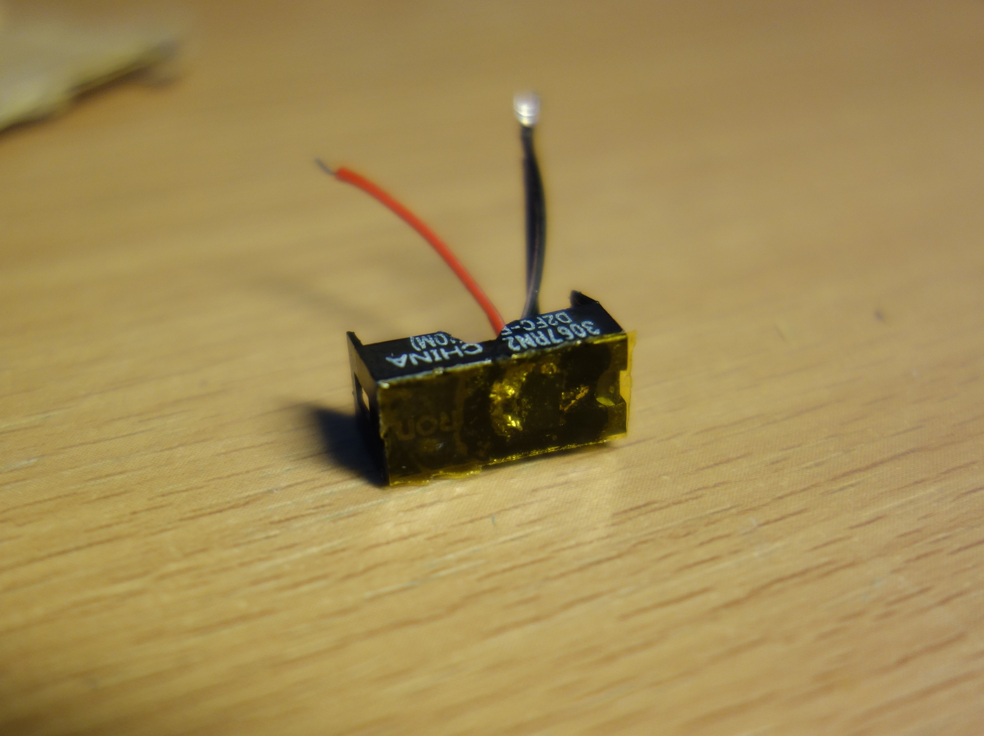
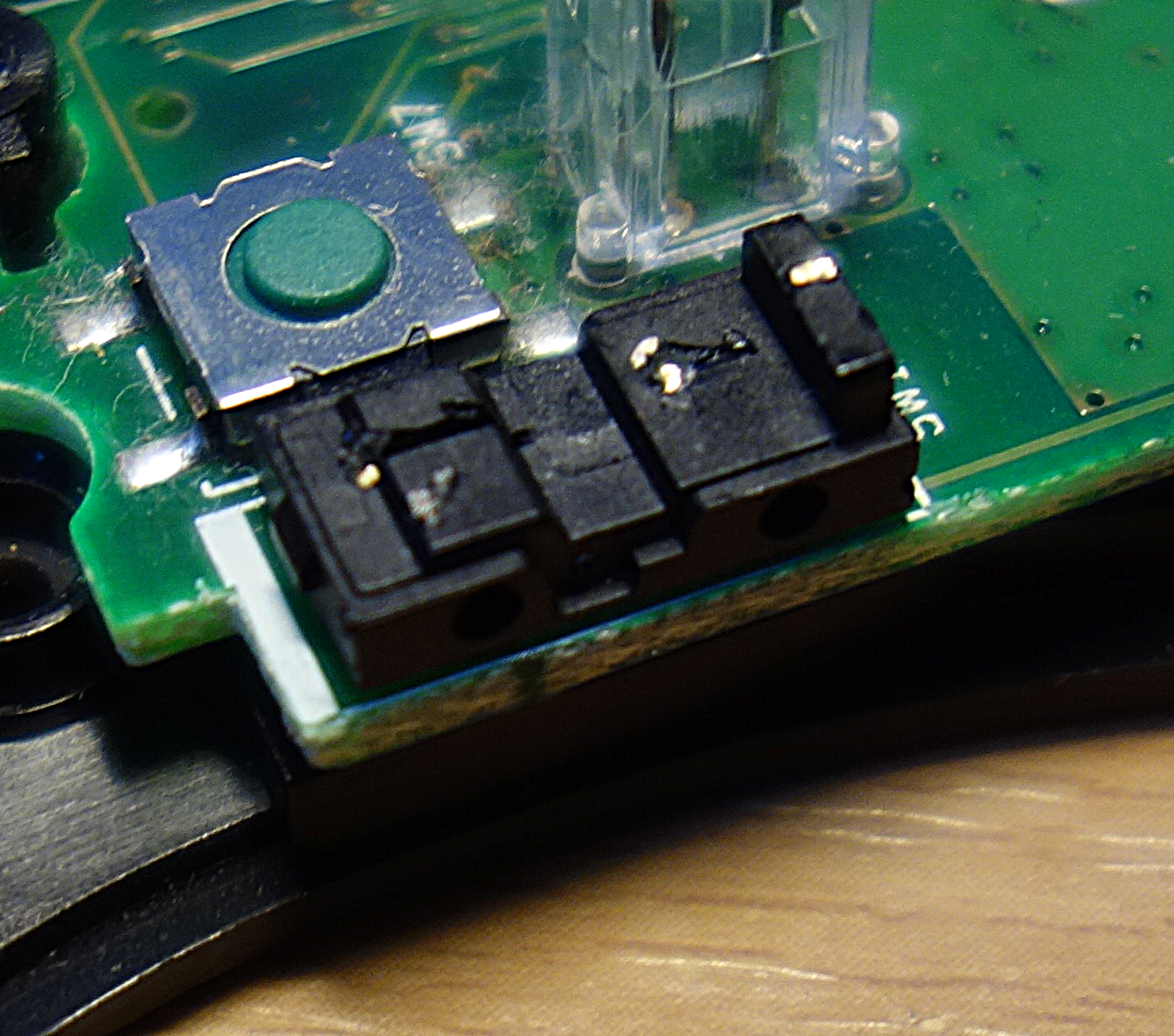
The next step is to remove all contact tires from the microswitch. This is necessary to prevent short circuits on these contacts when assembling a node with a Hall sensor, as well as to make room for this sensor. The body of the microswitch remains on the board, it is needed as a lid holder. This particular photo shows the core of the MX Revolution microswitch of the mouse, but it doesn’t matter, they are all the same (damn, what familiar words!).
Go to the top of the mouse body. H-shaped ribs on the end of the lever buttons need to grind off about 1 mm and glue this place a piece of self-adhesive magnetic rubber with a thickness of 0.3 mm. This is the source of the magnetic field for the operation of the Hall sensor.
The photo shows the initial state of the lever (left) and the lever with glued magnetic rubber (respectively, on the right).
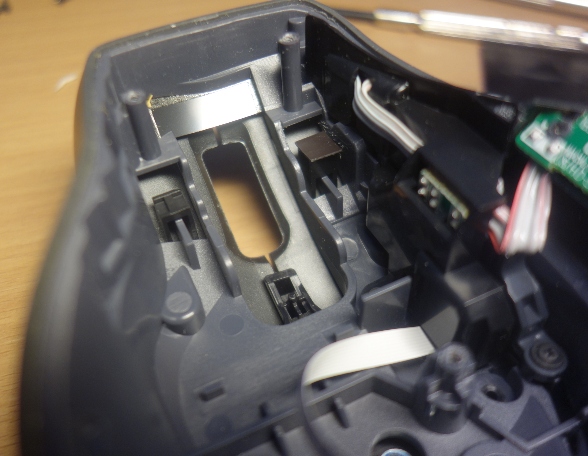
After assembling the microswitch case and soldering all the wires, the inside of the mouse looks like this:
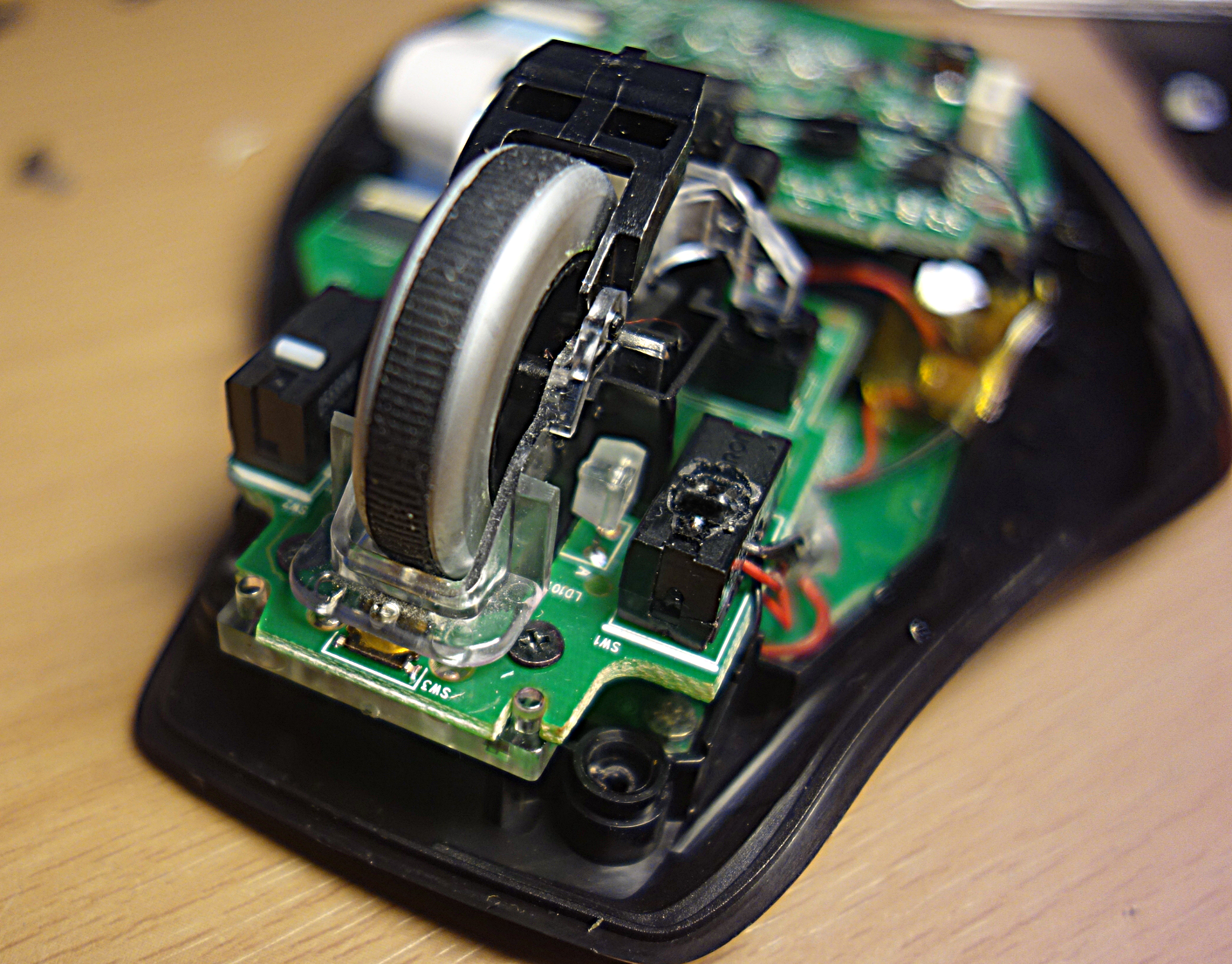
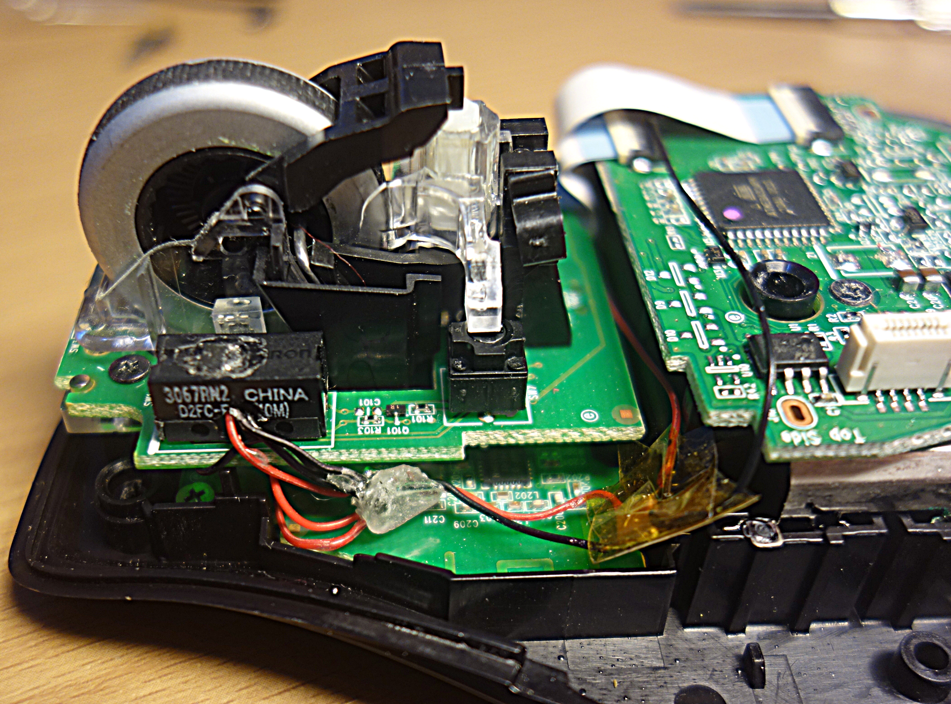
It remains only to assemble the corpus of the long-suffering mouse and enjoy the
There is no sense to alter the right microswitch, since it is rarely used and therefore lives much longer. The next step is the replacement of replaceable nickel-metal hydride batteries with non-replaceable lithium batteries with the possibility of wireless charging.
As they say in the circles opensource: have fun!
PS: published under the WTFPL license.
Source: https://habr.com/ru/post/393627/
All Articles