HUD speedometer - from idea to result
Hello!
I have not written anything for a long time, now it is more a news resource, and not a practical one. I'll try to correct the situation. I'll tell you about the development of a HUD-speedometer. Although not a laser projection , it is accessible and compact.
Introduction
It began with the fact that I got into the hands of large 3.3 "seven-segment indicators. I ordered them for watches that were not born. It was necessary to have 4 pieces, in lot 5, the Chinese put six. After evaluating the size, brightness and reflection from the windshield I decided - here it is. Due to the size, the split image is not visible, and the jacuzzi allows you to use it even in direct sun.I agree that the Chinese have beautiful finished pieces that are quite inexpensive (all prices at the time of this writing) are from 1800r. (close eyes on unsporting such a decision):
1. It is necessary to glue the film on the glass - although it is transparent, it still covers the review, but I do not like it when something is interfering with the glass. Slightly leaned back, moved the chair - and the film must be re-glued. Well, even with the film almost nothing is visible on a sunny day.
2. You can not glue the film, then tsiferki (they are quite small) are split, and nothing is visible in the sun.
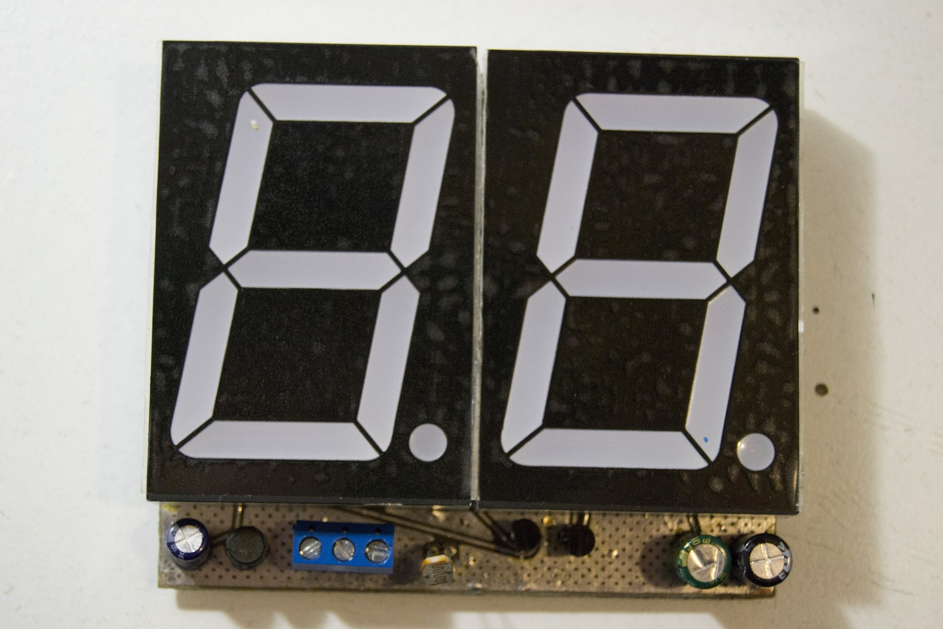
For the seed, the result is without film anywhere on the glass and even during the day:

Under the cat I promise a lot of pictures, mediocre video, code and text - all in the best traditions.
Theory
The idea is simple - for a fixed period of time we count the number of pulses from the speed sensor. As a simple and affordable CPU, ATMega8.
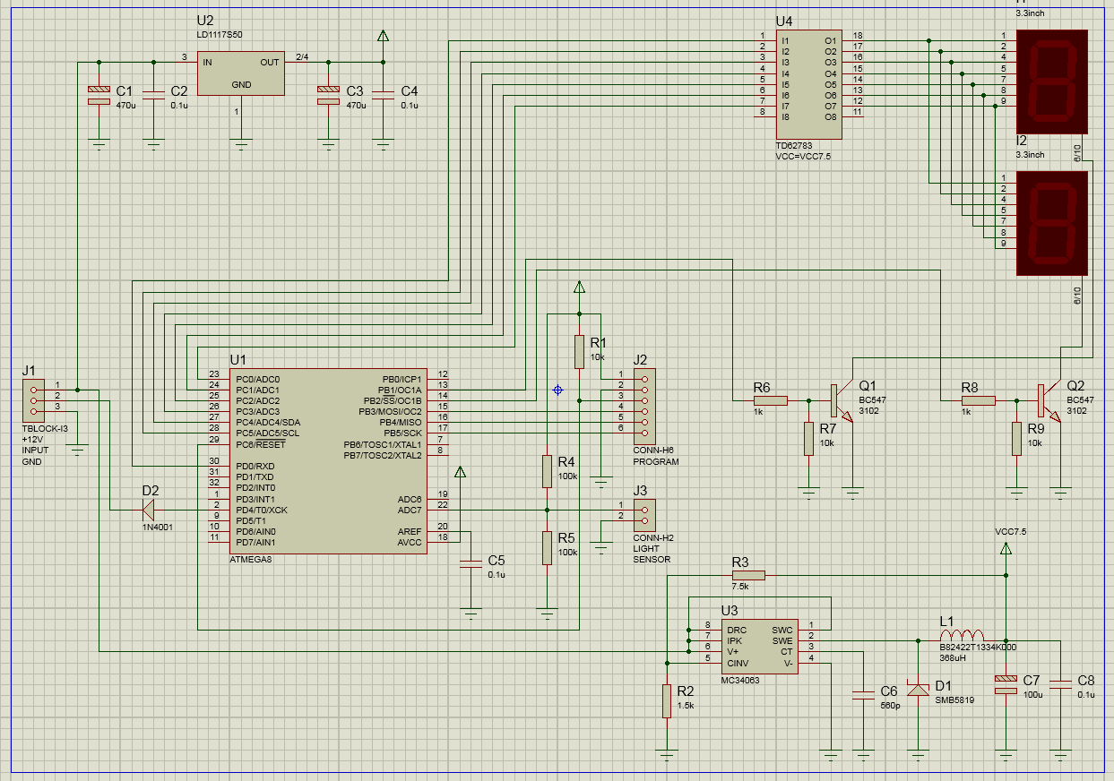
The first difficulty turned out to be in agreement with the MK 5 V and the 7.5 V indicators. Fantasy drew a circuit from a pack of transistors and resistors (7 elements with dynamic indication). Of all the Google, only one article about the replacement of indicators in the clock helped me, sorry I lost her address. Taking this opportunity, I convey my gratitude to the author for the idea of using TD62783 (from 5 pieces in a lot). Actually, this is a seven-segment indicator driver, inside a transistor assembly.
Next, a DC / DC converter. Made on the MC34063, I have a lot of them, I stock them. I counted on a calculator, checked it with a tester - 7.5 V. In the field trials it was not enough, the brightness was not enough, increased to 10 V.
The brightness is adjusted based on the readings of the light sensor, which is the usual Chinese photoresistor.
As a result, the scheme turned out this:
Practice
The PCB I threw TopoR . I took advantage of auto-placement, although I fixed most of the elements manually. But progress must work for me, and not only for progress. It turned out beauty:
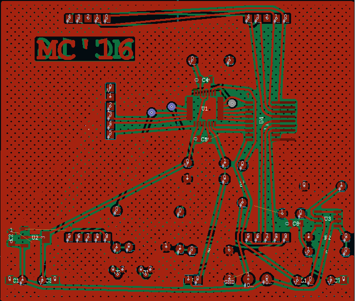

With the width of the U4 case I missed, I had to finish the tracks and did not solder the 11th leg.
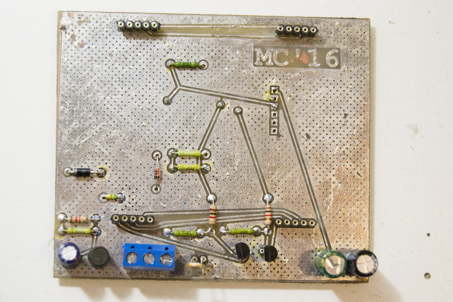
How it looks in real life:

The next nezhdanchik crept in the software (I will not tell you how I forgot to mirror the 2 and 5, 4 - there is nothing to be proud of). More difficult was the problem: the counter had the necessary number of pulses for too long. For example, at 60 km / h, counting 60 pulses from the speed sensor took more than a second. This rare update of the testimony did not suit me.
It was necessary to multiply each floor measurement by 2.
A linear change in brightness as compared to illumination did not fit: when it was slightly darker - the brightness was insufficient, when it was almost dark - the brightness was too much. Launched Excel, built a graph for different mathematical functions. In the end, I chose the square.

Bascom Code:
At the end of the 135 - correction factor, selected it for each machine individually (135 is for Logan, for Solaris was less - everyone has different speed sensors).
Promised video. Sorry for the quality, filmed on a piece of blue tape with one hand, ruled with the other:
')
Indicators do not light when the speed is less than 3 km / h. If the speed is greater than 99, it displays without the first character.
Budget:
ATMega8 - 200r for 5 pieces - 40r
Indicators - 825r for 10 pcs - 165r
TD62783 - 250r for 5 pieces - 50r
I had the rest of the payouts, but in general it is clear that you can meet the 500r.
More to tell and nothing. It turned out a big beautiful counter. Tested on Solaris. The focus failed, the focus was not a speed sensor. Slightly finish the program for working with OBD2 via ELM327.
Folder with the project on Yandex.Disk
Thank you all for your attention!
I have not written anything for a long time, now it is more a news resource, and not a practical one. I'll try to correct the situation. I'll tell you about the development of a HUD-speedometer. Although not a laser projection , it is accessible and compact.
Introduction
It began with the fact that I got into the hands of large 3.3 "seven-segment indicators. I ordered them for watches that were not born. It was necessary to have 4 pieces, in lot 5, the Chinese put six. After evaluating the size, brightness and reflection from the windshield I decided - here it is. Due to the size, the split image is not visible, and the jacuzzi allows you to use it even in direct sun.I agree that the Chinese have beautiful finished pieces that are quite inexpensive (all prices at the time of this writing) are from 1800r. (close eyes on unsporting such a decision):
1. It is necessary to glue the film on the glass - although it is transparent, it still covers the review, but I do not like it when something is interfering with the glass. Slightly leaned back, moved the chair - and the film must be re-glued. Well, even with the film almost nothing is visible on a sunny day.
2. You can not glue the film, then tsiferki (they are quite small) are split, and nothing is visible in the sun.
For the seed, the result is without film anywhere on the glass and even during the day:
Under the cat I promise a lot of pictures, mediocre video, code and text - all in the best traditions.
Theory
The idea is simple - for a fixed period of time we count the number of pulses from the speed sensor. As a simple and affordable CPU, ATMega8.
The first difficulty turned out to be in agreement with the MK 5 V and the 7.5 V indicators. Fantasy drew a circuit from a pack of transistors and resistors (7 elements with dynamic indication). Of all the Google, only one article about the replacement of indicators in the clock helped me, sorry I lost her address. Taking this opportunity, I convey my gratitude to the author for the idea of using TD62783 (from 5 pieces in a lot). Actually, this is a seven-segment indicator driver, inside a transistor assembly.
Next, a DC / DC converter. Made on the MC34063, I have a lot of them, I stock them. I counted on a calculator, checked it with a tester - 7.5 V. In the field trials it was not enough, the brightness was not enough, increased to 10 V.
The brightness is adjusted based on the readings of the light sensor, which is the usual Chinese photoresistor.
As a result, the scheme turned out this:
Practice
The PCB I threw TopoR . I took advantage of auto-placement, although I fixed most of the elements manually. But progress must work for me, and not only for progress. It turned out beauty:
With the width of the U4 case I missed, I had to finish the tracks and did not solder the 11th leg.
How it looks in real life:
The next nezhdanchik crept in the software (I will not tell you how I forgot to mirror the 2 and 5, 4 - there is nothing to be proud of). More difficult was the problem: the counter had the necessary number of pulses for too long. For example, at 60 km / h, counting 60 pulses from the speed sensor took more than a second. This rare update of the testimony did not suit me.
It was necessary to multiply each floor measurement by 2.
A linear change in brightness as compared to illumination did not fit: when it was slightly darker - the brightness was insufficient, when it was almost dark - the brightness was too much. Launched Excel, built a graph for different mathematical functions. In the end, I chose the square.
Bascom Code:
Hidden text
'HUD-speedometer
'17/01/2016
'21/01/2016
'v1.1

$regfile = "m8adef.dat"
$crystal = 4000000
$hwstack = 40
$swstack = 16
$framesize = 32

Config Portb = Output
Config Portc = Output
Config Portd = Output
Config Portd.4 = Input
Portd.4 = 1
Config Timer0 = Counter , Edge = Falling
Config Timer1 = Pwm , Pwm = 8 , Compare_a_pwm = Clear_up , Compare_b_pwm = Clear_up , Prescale = 8
Config Timer2 = Timer , Prescale = 1024
On Timer2 Mytimer2
Enable Interrupts
Enable Timer2
Config Adc = Single , Prescaler = Auto , Reference = Internal
Start Adc

Dim I As Byte '
Dim N As Byte '
Dim Pwm_value As Integer '
Dim Speed As Integer , Speed_half As Integer , First_symbol As Integer , Second_symbol As Integer
Dim A As Integer ' Speed Speed_half
Dim R1 As Word
Declare Sub Digit_indication(digit As Integer) '

Const P = 500
Const T = 5000 '
Const T1 = 1000 ' PWM
Pwm_value = 5
Tcnt0 = 0 '

Do
Incr I
If I = 25 Then '
R1 = Getadc(7)
R1 = Sqr(r1) '
R1 = R1 * 8
If R1 < 250 Then
Pwm_value = 250 - R1
Else
Pwm_value = 3 '
End If
I = 0
End If
Gosub Indication
Loop

Indication:
If Speed < 3 Then ' 0 - , 3 -
Pwm_value = 0
End If
While Speed > 99 '.. 2
Speed = Speed - 100
Wend
First_symbol = Speed / 10 '
Second_symbol = First_symbol * 10 '
Second_symbol = Speed - Second_symbol '
Pwm1b = 0
Pwm1a = 0
Waitus T1 '
Call Digit_indication(first_symbol) '
Pwm1b = Pwm_value
Waitus T
Pwm1b = 0
Pwm1a = 0
Waitus T1 '
Call Digit_indication(second_symbol)
Pwm1a = Pwm_value
Waitus T
Return

Sub Digit_indication(digit As Integer)
Select Case Digit
Case 0:
Portd.0 = 0
Portc.0 = 1
Portc.1 = 1
Portc.2 = 1
Portc.3 = 1
Portc.4 = 1
Portc.5 = 1
Case 1:
Portd.0 = 0
Portc.0 = 1
Portc.1 = 0
Portc.2 = 0
Portc.3 = 0
Portc.4 = 0
Portc.5 = 1
Case 2:
Portd.0 = 1
Portc.0 = 0
Portc.1 = 1
Portc.2 = 1
Portc.3 = 0
Portc.4 = 1
Portc.5 = 1
Case 3:
Portd.0 = 1
Portc.0 = 1
Portc.1 = 1
Portc.2 = 0
Portc.3 = 0
Portc.4 = 1
Portc.5 = 1
Case 4:
Portd.0 = 1
Portc.0 = 1
Portc.1 = 0
Portc.2 = 0
Portc.3 = 1
Portc.4 = 0
Portc.5 = 1
Case 5:
Portd.0 = 1
Portc.0 = 1
Portc.1 = 1
Portc.2 = 0
Portc.3 = 1
Portc.4 = 1
Portc.5 = 0
Case 6:
Portd.0 = 1
Portc.0 = 1
Portc.1 = 1
Portc.2 = 1
Portc.3 = 1
Portc.4 = 1
Portc.5 = 0
Case 7:
Portd.0 = 0
Portc.0 = 1
Portc.1 = 0
Portc.2 = 0
Portc.3 = 0
Portc.4 = 1
Portc.5 = 1
Case 8:
Portd.0 = 1
Portc.0 = 1
Portc.1 = 1
Portc.2 = 1
Portc.3 = 1
Portc.4 = 1
Portc.5 = 1
Case 9:
Portd.0 = 1
Portc.0 = 1
Portc.1 = 1
Portc.2 = 0
Portc.3 = 1
Portc.4 = 1
Portc.5 = 1
End Select
End Sub

Mytimer2:
Incr N
If N = 26 Then
N = 0
Speed = Tcnt0 'Speed =
Tcnt0 = 0 '
End If
If N = 13 Then '.. ( )
Speed_half = Tcnt0 * 2 '
A = Speed - Speed_half
A = A And &B0111111111111111 '
If A > 2 Then
Speed = Speed_half
End If
End If
Timer2 = 135 ' 135
Return
At the end of the 135 - correction factor, selected it for each machine individually (135 is for Logan, for Solaris was less - everyone has different speed sensors).
Promised video. Sorry for the quality, filmed on a piece of blue tape with one hand, ruled with the other:
')
Indicators do not light when the speed is less than 3 km / h. If the speed is greater than 99, it displays without the first character.
Budget:
ATMega8 - 200r for 5 pieces - 40r
Indicators - 825r for 10 pcs - 165r
TD62783 - 250r for 5 pieces - 50r
I had the rest of the payouts, but in general it is clear that you can meet the 500r.
More to tell and nothing. It turned out a big beautiful counter. Tested on Solaris. The focus failed, the focus was not a speed sensor. Slightly finish the program for working with OBD2 via ELM327.
Folder with the project on Yandex.Disk
Thank you all for your attention!
Source: https://habr.com/ru/post/393529/
All Articles