Smart wifi light switch

Good day, dear reader.
Some lyrics in the beginning. The idea of a "smart" light switch is not new at all and, probably, this is the first thing that comes to mind for those who began to get acquainted with the Arduino platform and IoT elements. And I am not an exception. After experimenting with the elements of the chains, motors and LEDs, I want to do something more applied, which is in demand in everyday life and, most importantly, it will be convenient to use, and will not remain a victim of the experiment in disagreement to comfort.
')
In this article I will tell you how I made a switch that will work as usual (that is, which is usually fixed on the wall) and at the same time allow you to control it via WiFi (or via the Internet, as it is done in this case).
So, we will make a list of what is needed for the implementation of our plans. I will say straight away that I intended not to spend much money on components and selected components based on the feedback on the forums and the price-to-quality ratio. Therefore, some components may seem out of place here for experienced electric drivers, but please do not judge strictly, because I'm just a newcomer to electrical engineering and I would really appreciate comments from more experienced specialists.
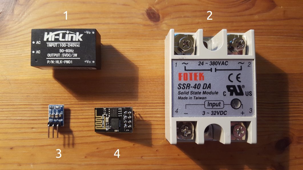
| No | Name | Description | Price |
|---|---|---|---|
| one | HLK-PM01 | Adapter 220VAC to 5VDC | 4,02 € |
| 2 | SSR-40DA | Solid state relay to control the current in the circuit | 3,35 € |
| 3 | AMS1117-3.3 | Voltage reducer from 5V to 3V | 1,29 € |
| four | ESP8266-01 | Wifi microcontroller | 2,35 € |
| Total: | 11,01 € | ||
I also needed: the server with which the switch will be controlled via the Internet, Arduino Uno, with which I programmed ESP, the router and consumables like wires, terminals, etc., all this can vary from taste and will not affect on the end result.
Prices are taken from Ebay, where I bought them.
Here are the elements from the table:
Now you can make and wiring diagram:

As you probably noticed, the scheme is very simple. Everything is assembled easily, quickly and without soldering. A kind of working prototype, which does not need to mess around for a long time. Everything is connected by wires and terminals. The only negative is that the relay does not fit into the switch socket. Yes, initially I planned to shove it all into the wall behind the switch to look aesthetically pleasing. But to my regret, there was little space in the nest and the relay simply did not fit either along or across:

Therefore, temporarily I took the relay to the socket, until I found a suitable switch box with a socket to hide the iron inside. But there is nothing more permanent than temporary, is there no? Therefore, it all looks like this now:
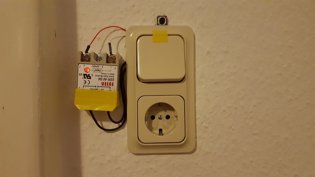
Insulating tape will save from electric shock ... I hope.
Now let's talk about the software part.
And before proceeding to the analysis of the code and details, I will give the general scheme of the implementation of the control light bulb.
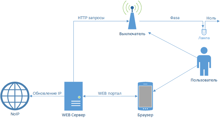
I hope that someday I will rewrite everything and the connection will be based on a faster protocol than HTTP, but for the beginning it will come down. Remotely the light bulb changes its state in approximately 1-1.5 seconds, and from the switch instantly, as befits a decent switch.
Programming ESP8266-01
The easiest way to do this is with the Arduino. You can download the necessary libraries for Arduino IDE from GitHub . There are all the instructions for installation and configuration.
Next, we need to connect the ESP to the computer, for this we need either a USB to Serial Adapter (such as FTDi , CH340 , FT232RL ) or any Arduino platform (I had an Arduino Uno) with RX and TX outputs.
It is worth noting that ESP8266-01 is powered by 3.3 Volts, which means that in no case do not connect it to the Arduino's power supply, which (often) is powered by 5 Volts, directly, otherwise everything will burn to hell. You can use the voltage reducer, which is shown in the table above.
The connection scheme is simple: we connect the TX , RX and GND ESP to the RX, TX and GND adapter / Arduino, respectively. After that, in fact, the connection is ready for use. The microcontroller can be programmed using the Arduino IDE.
A couple of nuances when using Arduino Uno:
- On Uno there is an output for 3.3V, but it was not enough. When ESP is connected to it, everything seems to be working, the indicators are lit, but the connection with the COM port is lost. So I used another 3.3V power supply for ESP.
- In addition, UNO had no problems communicating with ESP, given that UNO was powered by 5V, and ESP by 3B.
After several experiments with ESP8266-01, it turned out that ESPs are sensitive to voltages connected to GPIO0 and GPIO2. At the moment of launch, they should not be grounded in any way, if you intend to start it in normal mode. More details about the start of the microcontroller here . I did not know this and I had to slightly change the scheme, since In the ESP-01 version, only these 2 pins are present and both are used in my scheme.
Here is the ESP program itself:
Show code
#include <ESP8266WiFi.h> #include <WiFiClient.h> #include <ESP8266WebServer.h> #include <ESP8266mDNS.h> #include <ESP8266HTTPClient.h> extern "C" { // initVariant #include "user_interface.h" } const char* ssid = "WIFISSID"; // WiFi const char* password = "***************"; // WiFi const String self_token = "xxxxxxxxxxxxxxxxxxxxxxxxxxxxxxxx"; // const String serv_token = "xxxxxxxxxxxxxxxxxxxxxxxxxxxxxxxx"; // const String name = "IOT_lamp"; // , const String serverIP = "192.168.1.111"; // IP WEB bool lamp_on = false; bool can_toggle = false; int button_state; ESP8266WebServer server(80); // HTTPClient http; // const int lamp = 2; // GPIO2 const int button = 0; // "" GPIO0 // void handleRoot() { server.send(200, "text/plain", "Hello! I am " + name); } // void handleNotFound(){ String message = "not found"; server.send(404, "text/plain", message); } // void turnOnLamp(){ digitalWrite(lamp, LOW); lamp_on = true; } // void turnOffLamp(){ digitalWrite(lamp, HIGH); lamp_on = false; } // ./. void sendServer(bool state){ http.begin("http://"+serverIP+"/iapi/setstate"); String post = "token="+self_token+"&state="+(state?"on":"off"); // http.addHeader("Content-Type", "application/x-www-form-urlencoded"); int httpCode = http.POST(post); http.end(); } // void toggleLamp(){ if(lamp_on == true) { turnOffLamp(); sendServer(false); } else { turnOnLamp(); sendServer(true); } } // void handleOn(){ String token = server.arg("token"); if(serv_token != token) { String message = "access denied"; server.send(401, "text/plain", message); return; } turnOnLamp(); String message = "success"; server.send(200, "text/plain", message); } // void handleOff(){ String token = server.arg("token"); if(serv_token != token) { String message = "access denied"; server.send(401, "text/plain", message); return; } turnOffLamp(); String message = "success"; server.send(200, "text/plain", message); } // MAC IP void initVariant() { uint8_t mac[6] = {0x00, 0xA3, 0xA0, 0x1C, 0x8C, 0x45}; wifi_set_macaddr(STATION_IF, &mac[0]); } void setup(void){ pinMode(lamp, OUTPUT); pinMode(button, INPUT_PULLUP); // INPUT_PULLUP turnOffLamp(); WiFi.hostname(name); WiFi.begin(ssid, password); // WiFi while (WiFi.status() != WL_CONNECTED) { delay(500); } // server.on("/", handleRoot); server.on("/on", HTTP_POST, handleOn); server.on("/off", HTTP_POST, handleOff); server.onNotFound(handleNotFound); // server.begin(); } void loop(void){ server.handleClient(); // button_state = digitalRead(button); if (button_state == HIGH && can_toggle) { toggleLamp(); can_toggle = false; delay(500); } else if(button_state == LOW){ can_toggle = true; } } A couple of comments on the code:
- It is very important to declare a pin GPIO0 as pinMode (button, INPUT_PULLUP ), since in the circuit, we do not use a resistor for this button. And ESP has its own “stitched” for these very purposes.
- When catching the state of the button, it is desirable to set a delay when reading to avoid false triggering at the moment of pressing.
WEB server programming
Here you can give free rein to your imagination and use any means available to create a service that will process requests sent by the switch and send on / off requests.
I used Yii for this purpose. I chose this framework for several reasons, I needed autorization (since the portal is available on the Internet) and role management (for future experiments), and I also just like it. And now my management portal looks like this:
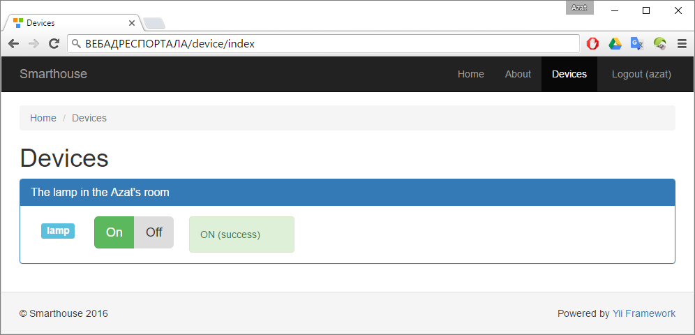
To control the light bulb in the network reach zone, the server itself would be enough for ESP. But you want to have logs, logic and other devices in the future, so it’s still better to use a separate server for management.
This is all about the portal, I think it makes no sense to write more about it, but if you have questions, I’ll be happy to answer them in the comments.
Instead of conclusion
Thank you if you have read the article to the end and may have found something useful in it. I will be glad to advice and criticism. In general, it still seems to me that the bottleneck in the circuit is the 5V Adapter and I will be glad if you share your experience in solving such problems. As for the ESP8266-01, so far it has not caused me any complaints except for the special use of GPIO pins. It works stably for the second week. Successes in projects.
Source: https://habr.com/ru/post/393497/
All Articles