Four-channel voltmeter 0-50V based on the set of "Digital Lab" NR05
Often there is a need to simultaneously control several voltages, for example, the output voltages of a computer power supply unit, several batteries, etc. In the last publication, we examined the principle of operation of the code lock, and now, based on the Digital Lab NR05 expansion board , we assemble a four-channel digital voltmeter with indication of results on the built-in board display. The range of measured voltages can be changed using an external divider, and the measurement step is determined by the digit capacity of the Atmega 328 microcontroller’s Atmega 328 microcontroller used in the Arduino board and amounts to 1024 values. Then, in the voltage range of 0-50V, the voltage measurement step will be about 50 mV, which is quite enough for domestic use.
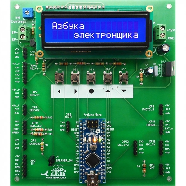
The measured voltages will be connected to the free analog inputs of the board. These are the inputs A0, A4, A5 and A7, located in the lower right of the board. To use the A0 input, temporarily drop the resistor R4 located near the XP3 connector on the bottom right of the board.

')
An external divider with connectors for connecting measured voltages and expansion boards will be manufactured using the LUT method (the so-called “laser-iron technology”) and weed the board in a solution of ferric chloride. We used SMD resistors, but if you do not have a laser printer, you can make a divider by drawing the conductors with a waterproof felt-tip pen. In this case, it is better to use output resistors, since the dimensional accuracy of the resulting conductors will be lower. In detail, the manufacturing technology of printed circuit boards by the method of etching in ferric chloride can be studied by purchasing the Master Kit production set NN201 .
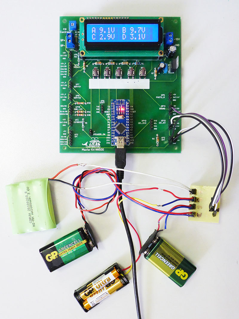
The finished divider board is shown in the photo below.

The expansion board has a 2-line LCD indicator with 16 characters in each line. On this indicator, four readings from 0 to 50 volts with one decimal place and channel IDs will be quite comfortable.
The measurements themselves should be carried out several times over a short period of time, averaging their values. So we will reduce random measurement errors.
We also realize in the program “freezing” the results when you click on one of the buttons built into the board, for example, the middle one. With a second press, continuous measurements will resume.
We activate the LED connected to the 13th digital output of Arduino to indicate the measurement process.
In view of the above, we will create a program for Arduino:
The program is provided with sufficiently detailed comments explaining the features of the implementation of the algorithm.
Perhaps the most important feature is the process of calibration of the constants described in the comments, which are involved in the calculation of the measured voltages. To calibrate the divider (made once), you should use a stable constant voltage source. Taking into account that the calibration takes a short time, you can successfully use a 9V battery of the “Krona” type and a digital multimeter. A multimeter from the "Set of the young electronics engineer" NR02 is quite suitable. This kit is also great for teaching soldering and PCB assembly.
It should be noted that when the supply voltage to the Arduino changes, it is necessary to change the calibration values of the reference voltage, the relative values of which are measured values.
To change the measurement range, you must apply a divider with a different division factor of the input voltage.
The measured voltages will be connected to the free analog inputs of the board. These are the inputs A0, A4, A5 and A7, located in the lower right of the board. To use the A0 input, temporarily drop the resistor R4 located near the XP3 connector on the bottom right of the board.
')
An external divider with connectors for connecting measured voltages and expansion boards will be manufactured using the LUT method (the so-called “laser-iron technology”) and weed the board in a solution of ferric chloride. We used SMD resistors, but if you do not have a laser printer, you can make a divider by drawing the conductors with a waterproof felt-tip pen. In this case, it is better to use output resistors, since the dimensional accuracy of the resulting conductors will be lower. In detail, the manufacturing technology of printed circuit boards by the method of etching in ferric chloride can be studied by purchasing the Master Kit production set NN201 .
The finished divider board is shown in the photo below.
The expansion board has a 2-line LCD indicator with 16 characters in each line. On this indicator, four readings from 0 to 50 volts with one decimal place and channel IDs will be quite comfortable.
The measurements themselves should be carried out several times over a short period of time, averaging their values. So we will reduce random measurement errors.
We also realize in the program “freezing” the results when you click on one of the buttons built into the board, for example, the middle one. With a second press, continuous measurements will resume.
We activate the LED connected to the 13th digital output of Arduino to indicate the measurement process.
In view of the above, we will create a program for Arduino:
Spoiler
/ * ------------------------------------------------ --------------
Four-channel voltmeter 0-50V, with averaging,
one digit after the decimal point, with display on the LCD-indicator
16 characters, 2 lines,
Used expansion card from a set of Master Kit
NR05 "Digital Laboratory"; 4 dividers for 10 on resistors
1M, 100k connected with analog inputs A0, A4, A5, A7
Voltage Reference Calibration
Measure the voltage of 5V and change the values of the constant V_REF
according to the measured value.
Measure Voltage with LCD Connected
and with a running sketch.
Determination of the calibration values of the dividers (held
for each divider)
Connect the stable voltage Vin to the input of the divider and
measure it.
Measure the voltage Vout at the output of the divider.
The calibration DIV_ * value will be Vin / Vout.
The project is based on startingelectronics.com
-------------------------------------------------- ------------ * /
#include <LiquidCrystal.h>
// built-in LED (used to indicate the measurement process)
#define LED 13
// number of samples per measurement
#define NUM_SAMPLES 20
// divider calibration values
#define DIV_1 11.186
#define DIV_2 11.186
#define DIV_3 11.186
#define DIV_4 11.186
// calibration value of the reference voltage
#define V_REF 4.575
// number of buttons on the board
#define NUM_KEYS 5
// calibration values for each button (derived experimentally)
int adcKeyVal [NUM_KEYS] = {30, 150, 360, 535, 760};
LiquidCrystal lcd (A1, A2, A3, 2, 4, 7);
unsigned long sum [4] = {0}; // sum of samples in each channel
unsigned char sample_count = 0; // current sample number
float voltage [4] = {0.0}; // calculated voltage
int cnt = 0; // service variable
int keyIsPressed = 0; // flag of pressing the “freezing” button of measurements
void setup ()
{
lcd.begin (16, 2);
pinMode (LED, OUTPUT);
digitalWrite (LED, LOW);
}
void loop ()
{
// if button 3 is pressed, we invert the flag of pressing the “freezing” button
if (get_key () == 3) {
keyIsPressed =! keyIsPressed;
delay (500);
}
// if the flag is set (1), the information on the display is not updated
if (keyIsPressed == 0) {
digitalWrite (LED, LOW);
// take samples in each channel and summarize them
while (sample_count <NUM_SAMPLES) {
// sample channel A0, A4, A5, A7
sum [0] + = analogRead (A0);
sum [1] + = analogRead (A4);
sum [2] + = analogRead (A5);
sum [3] + = analogRead (A7);
sample_count ++;
delay (10);
}
digitalWrite (LED, HIGH);
// calculate the voltage in each channel by averaging the samples
for (cnt = 0; cnt <4; cnt ++) {
voltage [cnt] = ((float) sum [cnt] / (float) NUM_SAMPLES * V_REF) / 1024.0;
}
// display the values on the idicator
lcd.setCursor (0, 0);
lcd.print (“A„);
lcd.print (voltage [0] * DIV_1, 1);
lcd.print (“V„);
// voltage 2 - B (A4 pin)
lcd.setCursor (8, 0);
lcd.print (“B„);
lcd.print (voltage [1] * DIV_2, 1);
lcd.print (“V„);
// voltge 3 - C (pin A5)
lcd.setCursor (0, 1);
lcd.print (“C„);
lcd.print (voltage [2] * DIV_3, 1);
lcd.print (“V„);
// voltage 4 - D (pin A7)
lcd.setCursor (8, 1);
lcd.print (“D„);
lcd.print (voltage [3] * DIV_4, 1);
lcd.print (“V„);
// reset the counter and the amount
sample_count = 0;
for (cnt = 0; cnt <4; cnt ++) sum [cnt] = 0;
delay (20);
}
}
// function returns the number of the button pressed
int get_key ()
{
int input = analogRead (A6);
int k;
for (k = 0; k <NUM_KEYS; k ++)
if (input <adcKeyVal [k])
return k + 1;
return 0;
}
The program is provided with sufficiently detailed comments explaining the features of the implementation of the algorithm.
Perhaps the most important feature is the process of calibration of the constants described in the comments, which are involved in the calculation of the measured voltages. To calibrate the divider (made once), you should use a stable constant voltage source. Taking into account that the calibration takes a short time, you can successfully use a 9V battery of the “Krona” type and a digital multimeter. A multimeter from the "Set of the young electronics engineer" NR02 is quite suitable. This kit is also great for teaching soldering and PCB assembly.
It should be noted that when the supply voltage to the Arduino changes, it is necessary to change the calibration values of the reference voltage, the relative values of which are measured values.
To change the measurement range, you must apply a divider with a different division factor of the input voltage.
Source: https://habr.com/ru/post/393225/
All Articles