New nooLite MR1132 receiver module for Arduino

In this article we will discuss a new module of the receiver of the nooLite system for Arduino and microcontrollers. What is remarkable about this module? Until now, there were no ways to receive information from sensors and control the on-air transmission of signals from nooLite system consoles on microcontrollers and Arduino, such a possibility existed only for computers, using special USB adapters.
Now, with the release of the MR1132 module, it is possible to receive data on temperature, humidity, light and the presence of people in the room from the wireless sensors of the nooLite system in your sketches on Arduino, it is possible to track the commands given by the nooLite power units with remote control switches and much more that was previously unavailable.
')
In this article I will tell you about the work of this module and give a working sketch, on the basis of which you can easily create your devices on the MR1132. In subsequent articles I will talk about the integration of this module with the popular Arduino Mega Server system and about the great opportunities that will arise in connection with this integration.
Module
The MR1132 module is very similar to its brother, the MT1132 module (about which there was already a cycle of articles on Hiktatimes one , two , three ). The difference is that the MT1132 module is a transmitter, and the MR1132 module is a receiver and the greatest effect can be obtained by sharing them.
Another important point is that the MT1132 transmitter is versatile and operates on both 3.3 V and 5 V (and therefore also works with 3.3-volt controllers and 5-volt), and the receiver only from 5 V. This should be taken into account when designing your devices and, if necessary, use logical level coordinators.

The connection is as simple as the MT1132 module - the supply voltage, ground and two contacts RX and TX. RTS can be pulled up to the supply voltage, but everything worked for me without connecting this pin.
Job
The module operates on a serial interface at a speed of 9600. The module receives commands from the controller and, in turn, provides data received from the air (from sensors and nooLite consoles).
Let's take a closer look at this moment so that you have a clear understanding of how this module works.
All commands that the controller can send to the module via the serial interface refer to the “binding” or “decoupling” of nooLite devices, from which the module will then receive data. There are no other control commands for this module. For example, you tied a nooLite PT112 temperature sensor on the zero channel (total channels 32, which is reflected in the module name) and after that the module will start receiving data from this sensor and output them to the serial interface (where our task is to “catch” them and use for our goals).
If we no longer need to receive data from any sensor, then we can send an unlink command (in this case, on the zero channel) and the receiver will no longer issue information to the controller from this sensor.
As for the information received by the module MR1132 from nooLite devices, there is a separate document that describes the format of all possible commands. We, in the context of this narrative, from all this extensive list will be interested in teams of sensors for temperature, humidity and movement. Details of these commands will be discussed below, on the example of the sketch.
Sensors
Three sensors will be used in our experiments.
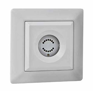
PT112 temperature sensor and PT111 temperature and humidity sensor. They look the same and work exactly the same way, the difference is that PT112 provides only information about temperature, and PT111 gives information about temperature and humidity. These sensors can operate in both a simple sensor mode and in thermostat mode and a hygrostat mode, but we will be interested in the simple sensor mode.
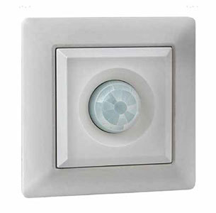
The third sensor is PM111. This is a motion sensor that can directly control the power units of nooLite, but it will interest us only as a source of information about the movement and presence of people in the room.
Controller
The Arduino Mega 2560 will be used as the controlling controller, and its two serial interfaces will be Serial (for visual information control) Serial2 (for communication with the receiver module). Serial1 is reserved for the MT1132 transmitter module.

Sketch
In the setup () section, two interfaces are launched, an informational message about the start of the sketch is displayed, and a command is issued to link the nooLite devices on the zero channel. This is a test command and you can comment it out or replace it with another command (for example, bindings on another channel or decoupling).
void setup() { Serial.begin(9600); Serial2.begin(9600); Serial.println("*** Start sketch ***"); mrBind(0); //mrUnbind(0); } Before working with the sketch, you need to perform some preliminary actions, namely, to bind your sensors to the module as follows:
PT112 - zero channel
PT111 - first channel
PM111 - second channel
To do this, you need to run the sketch three times, changing the binding command
mrBind(0); mrBind(1); mrBind(2); and each time press the button on the corresponding sensor. This needs to be done only once, then the binding command can be commented out. Or, instead, put a decoupling command and untie any of the attached sensors.
In the loop () section there is only one function mrCheck (), which is responsible for “catching” the messages of the MR1132 module from the serial interface Serial2.
void mrCheck() { if (Serial2.available() == 8) { mrBuf[0] = Serial2.read(); mrBuf[1] = Serial2.read(); mrBuf[2] = Serial2.read(); mrBuf[3] = Serial2.read(); if (mrBuf[0] == 79 && mrBuf[1] == 75 && mrBuf[2] == 13 && mrBuf[3] == 10) { Serial.println("OK"); } else { mrBuf[4] = Serial2.read(); mrBuf[5] = Serial2.read(); mrBuf[6] = Serial2.read(); mrBuf[7] = Serial2.read(); mrNewData(); } } } This function fills the mrBuf [8] array with incoming data from the module or transmits to the Serial the “OK” message issued by the MR1132 module. Further, the contents of the mrBuf [8] array are parsed in accordance with the data format of the nooLite system commands, and the corresponding sketch functions are involved in this.
The mrNewData () function extracts the main data from the mrBuf array [8] and, depending on the incoming command, provides the necessary information to Serial (channel, command, temperature, humidity, sensor battery status, etc.).
void mrNewData() { mrClearData(); mrPrintHeader(); mrSetBindState(); mrPrintBindState(); mrSetChannel(); mrPrintChannel(); mrSetCommand(); mrSetDatas(); switch (mrCommand) { case 0: Serial.print("PIR command: ");Serial.println("OFF"); break; case 2: Serial.print("PIR command: "); Serial.println("ON"); break; case 21: mrSetDeviceType(); mrPrintDeviceType(); if (mrDeviceType == 1) { mrSetTemperature(); mrPrintTemperature(); } if (mrDeviceType == 2) { mrSetTemperature(); mrPrintTemperature(); mrSetHumidity(); mrPrintHumidity(); } break; default: ; } // switch mrSetBatteryState(); } // newData() Functions containing the word Print in their names are engaged in outputting information to the Serial interface for visual control.
The following functions are used to decrypt data located in the mrBuf array [8], in accordance with the data format of the nooLite system commands:
mrSetTogl () - the value of the counter of incoming teams
mrSetBindState () - module state (binding / norm)
mrSetReceiveBit () - control bit for receiving a new command
mrSetChannel () - channel number
mrSetCommand () - command
mrSetFormat () - data format
mrSetDeviceType () - sensor type
mrSetDatas () - filling four data bytes
mrSetTemperature () - getting the temperature value
mrSetHumidity () - getting the moisture value
mrSetBrightness () - getting the light value
mrSetBatteryState () - sensor battery status
You can see the details of the implementation of these functions in the full sketch code attached below.
Here is the full text of the sketch.
Full sketch code
// TX2 16
// RX2 17
// TX1 18
// RX1 19
// nooLite MR1132 data
byte mrBuf [8];
int mrTogl = -1;
int mrBindState = -1;
int mrReceiveBit = -1;
int mrChannel = -1;
int mrCommand = -1;
int mrFormat = -1;
int mrData0 = -1;
int mrData1 = -1;
int mrData2 = -1;
int mrData3 = -1;
int mrDeviceType = -1;
int mrBatteryState = -1;
int mrHumidity = -1;
int mrBrightness = -1;
float mrTemp = -1.0;
// nooLite MR1132 bind / unbind
void mrSerialChannel (byte ch) {
switch (ch) {
case 0: Serial.println ("0"); break;
case 1: Serial.println ("1"); break;
case 2: Serial.println ("2"); break;
case 3: Serial.println ("3"); break;
case 4: Serial.println ("4"); break;
case 5: Serial.println ("5"); break;
case 6: Serial.println ("6"); break;
case 7: Serial.println ("7"); break;
case 8: Serial.println ("8"); break;
case 9: Serial.println ("9"); break;
case 10: Serial.println ("10"); break;
case 11: Serial.println ("11"); break;
case 12: Serial.println ("12"); break;
case 13: Serial.println ("13"); break;
case 14: Serial.println ("14"); break;
case 15: Serial.println ("15"); break;
case 16: Serial.println ("16"); break;
case 17: Serial.println ("17"); break;
case 18: Serial.println ("18"); break;
case 19: Serial.println ("19"); break;
case 20: Serial.println ("20"); break;
case 21: Serial.println ("21"); break;
case 22: Serial.println ("22"); break;
case 23: Serial.println ("23"); break;
case 24: Serial.println ("24"); break;
case 25: Serial.println ("25"); break;
case 26: Serial.println ("26"); break;
case 27: Serial.println ("27"); break;
case 28: Serial.println ("28"); break;
case 29: Serial.println ("29"); break;
case 30: Serial.println ("30"); break;
case 31: Serial.println ("31"); break;
} // switch
} // mrSerialChannel ()
void mrSerial2Channel (byte ch) {
switch (ch) {
case 0: Serial2.print (“00”); break;
case 1: Serial2.print ("01"); break;
case 2: Serial2.print ("02"); break;
case 3: Serial2.print ("03"); break;
case 4: Serial2.print ("04"); break;
case 5: Serial2.print ("05"); break;
case 6: Serial2.print (“06”); break;
case 7: Serial2.print (“07”); break;
case 8: Serial2.print ("08"); break;
case 9: Serial2.print (“09”); break;
case 10: Serial2.print ("10"); break;
case 11: Serial2.print ("11"); break;
case 12: Serial2.print ("12"); break;
case 13: Serial2.print ("13"); break;
case 14: Serial2.print ("14"); break;
case 15: Serial2.print ("15"); break;
case 16: Serial2.print ("16"); break;
case 17: Serial2.print ("17"); break;
case 18: Serial2.print ("18"); break;
case 19: Serial2.print ("19"); break;
case 20: Serial2.print ("20"); break;
case 21: Serial2.print ("21"); break;
case 22: Serial2.print ("22"); break;
case 23: Serial2.print ("23"); break;
case 24: Serial2.print ("24"); break;
case 25: Serial2.print ("25"); break;
case 26: Serial2.print ("26"); break;
case 27: Serial2.print ("27"); break;
case 28: Serial2.print ("28"); break;
case 29: Serial2.print ("29"); break;
case 30: Serial2.print ("30"); break;
case 31: Serial2.print ("31"); break;
} // switch
} // mrSerial2Channel ()
void mrPrintBind (byte ch) {
Serial.print (“Bind on channel„);
mrSerialChannel (ch);
}
void mrBind (byte ch) {
mrPrintBind (ch);
Serial2.print (“bind_mode_cell_”);
mrSerial2Channel (ch);
Serial2.write (3); // End of Text - B00000011 (BIN)
}
void mrPrintUnbind (byte ch) {
Serial.println (“Unbind on channel„);
mrSerialChannel (ch);
}
void mrUnbind (byte ch) {
mrPrintUnbind (ch);
Serial2.print (“clear_one_cell_”);
mrSerial2Channel (ch);
Serial2.write (3);
}
void mrBindStop () {
Serial.println ("Bind mode off");
Serial2.print ("bind_mode_off");
Serial2.write (3);
}
void mrClearAll () {
Serial.println ("Clear all cell");
Serial2.print ("clear_all_cell");
Serial2.write (3);
}
// nooLite MR1132 print works
void mrPrintHeader () {
Serial.println ();
}
void mrPrintDeviceType () {
Serial.print (“Device:„);
if (mrDeviceType == 1) {
Serial.println (“PT112”);
}
if (mrDeviceType == 2) {
Serial.println ("PT111");
}
}
void mrPrintBindState () {
if (mrBindState == 1) {
Serial.print (“Bind State:„);
Serial.println (“ON”);
}
}
void mrPrintBatteryState () {
if (mrBatteryState == 1) {
Serial.print (“Battery State:„);
Serial.println (“LOW!”);
}
}
void mrPrintChannel () {
Serial.print (“Channel:„);
Serial.println (mrChannel);
}
void mrPrintTemperature () {
Serial.print (“Temp:„);
Serial.println (mrTemp);
}
void mrPrintHumidity () {
Serial.print (“Humidity:„);
Serial.println (mrHumidity);
}
// nooLite MR1132 data works
void mrClearData () {
mrTogl = -1;
mrBindState = -1;
mrReceiveBit = -1;
mrChannel = -1;
mrCommand = -1;
mrFormat = -1;
mrData0 = -1;
mrData1 = -1;
mrData2 = -1;
mrData3 = -1;
mrDeviceType = -1;
mrBatteryState = -1;
mrHumidity = -1;
mrBrightness = -1;
mrTemp = -1.0;
}
void mrSetTogl () {
byte b0 = bitRead (mrBuf [0], 0);
byte b1 = bitRead (mrBuf [0], 1);
byte b2 = bitRead (mrBuf [0], 2);
byte b3 = bitRead (mrBuf [0], 3);
byte b4 = bitRead (mrBuf [0], 4);
byte b5 = bitRead (mrBuf [0], 5);
mrTogl = 32 * b5 + 16 * b4 + 8 * b3 + 4 * b2 + 2 * b1 + b0;
}
void mrSetBindState () {
mrBindState = bitRead (mrBuf [0], 6);
}
void mrSetReceiveBit () {
mrReceiveBit = bitRead (mrBuf [0], 7);
}
void mrSetChannel () {
mrChannel = mrBuf [1];
}
void mrSetCommand () {
mrCommand = mrBuf [2];
}
void mrSetFormat () {
mrFormat = mrBuf [3];
}
void mrSetDeviceType () {
byte tp1 = bitRead (mrBuf [5], 4);
byte tp2 = bitRead (mrBuf [5], 5);
byte tp3 = bitRead (mrBuf [5], 6);
mrDeviceType = 4 * tp3 + 2 * tp2 + tp1;
}
void mrSetDatas () {
mrData0 = mrBuf [4];
mrData1 = mrBuf [5];
mrData2 = mrBuf [6];
mrData3 = mrBuf [7];
}
void mrSetTemperature () {
byte t8 = bitRead (mrData1, 0);
byte t9 = bitRead (mrData1, 1);
byte t10 = bitRead (mrData1, 2);
int temp2 = 1024 * t10 + 512 * t9 + 256 * t8;
int temp = mrData0 + temp2;
byte t11 = bitRead (mrData1, 3);
if (t11 == 1) {
temp = (4096 - temp) * -1;
}
mrTemp = (float) temp / 10.0;
}
void mrSetBatteryState () {
mrBatteryState = bitRead (mrBuf [5], 7);
}
void mrSetHumidity () {
mrHumidity = mrData2;
}
void mrSetBrightness () {
mrBrightness = mrData3;
}
void mrNewData () {
mrClearData ();
mrPrintHeader ();
mrSetBindState ();
mrPrintBindState ();
mrSetChannel ();
mrPrintChannel ();
mrSetCommand ();
mrSetDatas ();
switch (mrCommand) {
case 0:
Serial.print (“PIR command:„); Serial.println (“OFF”);
break;
case 2:
Serial.print (“PIR command:„); Serial.println (“ON”);
break;
case 21:
mrSetDeviceType ();
mrPrintDeviceType ();
if (mrDeviceType == 1) {
mrSetTemperature ();
mrPrintTemperature ();
}
if (mrDeviceType == 2) {
mrSetTemperature ();
mrPrintTemperature ();
mrSetHumidity ();
mrPrintHumidity ();
}
break;
default:
;
} // switch
mrSetBatteryState ();
} // newData ()
void mrCheck () {
if (Serial2.available () == 8) {
mrBuf [0] = Serial2.read ();
mrBuf [1] = Serial2.read ();
mrBuf [2] = Serial2.read ();
mrBuf [3] = Serial2.read ();
if (mrBuf [0] == 79 && mrBuf [1] == 75 && mrBuf [2] == 13 && mrBuf [3] == 10) {
Serial.println ("OK");
} else {
mrBuf [4] = Serial2.read ();
mrBuf [5] = Serial2.read ();
mrBuf [6] = Serial2.read ();
mrBuf [7] = Serial2.read ();
mrNewData ();
}
}
}
void setup () {
Serial.begin (9600);
Serial2.begin (9600);
Serial.println ("*** Start sketch ***");
mrBind (0);
// mrUnbind (0);
}
void loop () {
mrCheck ();
} // loop ()
Conclusion
That's all you need to start working with the MR1132 module and use it in your sketches and projects. This module can also be used to control the signals from the nooLite wall consoles and your system can now know where and which console worked and what command it sent to power units.
A new 0.15 version of the popular Arduino Mega Server system is coming soon and this version will include built-in support for the MR1132 modules and convenient management of them directly from a web page and much more interesting.
Source: https://habr.com/ru/post/393185/
All Articles