Alteration of the push-button radio switch to touch
I had long dreamed of installing a touch switch at home, the dream came true when I was presented with an inexpensive FD Electronics touch switch. Looks nice, works great. But this is just a switch, and I have a smart home based on Z-Wave and of course I wanted to integrate it into my system.
FD Electronics, Livolo and DeLumo have radio switches operating at 433 MHz and 868 MHz, respectively, but integrating them into a smart home will not work. These switches work only with the consoles of the same manufacturers, there is no control from the computer, there is no feedback, i.e. if someone turns on the light, I won't find out.
')
It was decided to cross a
The most popular chip for creating a touch button is the TTP-223 . The main feature of the TTP-223 is the ability to auto-calibrate. When power is applied, the microcircuit measures the capacitance on the sensor I leg and takes it as 0, which is convenient since there is no need to adjust anything. When touching the sensor, voltage appears on the Q leg, there we connect the load (LED, relay, optocoupler).

Using the TOG and AHLB legs, you can adjust the response to touching the sensor. I set up the switch-on mode by connecting the TOG and AHLB to the ground, which means that when I touch the sensor on Q leg, the voltage appears, when I release the sensor, the voltage disappears. You can also set the switching mode, then each touch takes the Q leg to the opposite state.
For the TTP-223 test on a breadboard, I assembled a relay control circuit for the Arduino. It works great.

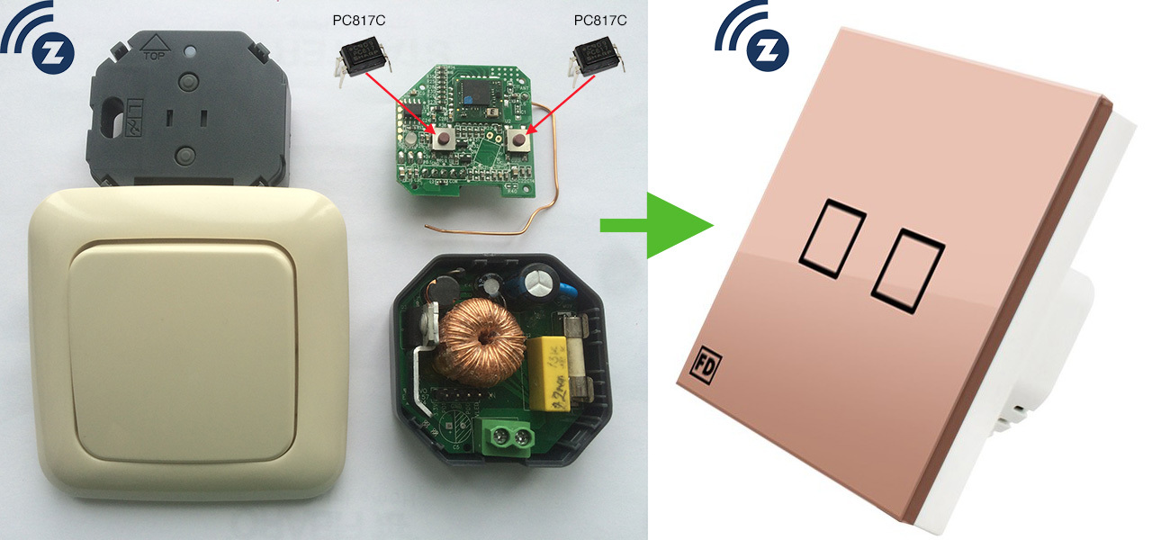
To simulate the pressing of physical buttons, I used PC817C optocoupler. I soldered optocouplers instead of buttons to my dimmer. When voltage is applied to the optocoupler, it closes; for a dimmer, it is as if the button was pressed. With the help of LUT, an adapter board was made, on the one hand, the sensor circuit, on the other side of the optocoupler.

Combining this whole sandwich I got a touch-sensitive Z-Wave dimmer. All tests and assembly took 2 pm. The switch is installed in the corridor, where it is controlled by a motion sensor, and if you need to forcibly turn it off or on at a certain level of brightness, you can lightly touch the beautiful!

Ps. I decided to use the experience to create a battery-operated touch switch, and I already ordered a touch panel from a Livolo switch with aliexpress, but more on that later.
Source: https://habr.com/ru/post/392857/
All Articles