Universal Controller Module for Internet of Things
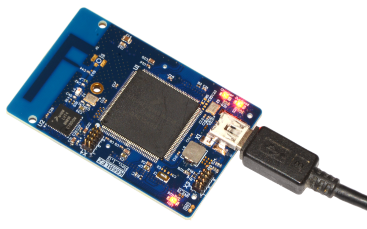
K66BLEZ1 - module board for the development of a wide class of devices mainly in the field of IoT , wearable electronics and small automation. It features a variety of I / O ports and interfaces, which gives it extraordinary versatility. Created on the latest NXP microcontrollers from the Kinetis family. It has onboard a radio module with support for Bluetooth LE 4.2 and ZigBee . There are also connectors for microSD cards and USB 2.0 HS with support for the device , host , OTG modes and a 3.6 V lithium battery charger. On the bottom side there are two connectors of 60 contacts each. There is a non-volatile real-time clock with a separate battery. The fee is accompanied by open source software .
Briefly about the board.
The board has two microcontrollers: MK66FN2M0VLQ18 (180 MHz, 2 MB Flash, 256 KB RAM) and MKW40Z160VHT4 (48 MHz, 160 KB Flash, 20 KB RAM) . The first for the main application and the second for wireless communication. The 90 signal pins of the MK66 microcontroller are routed to two external connectors.
')
| Module board 6 layer with an integrated PCB antenna at 2.4 GHz. Material - high temperature textolite FR4, allowing repeated soldering. Coating - Immersion gold ENIG . 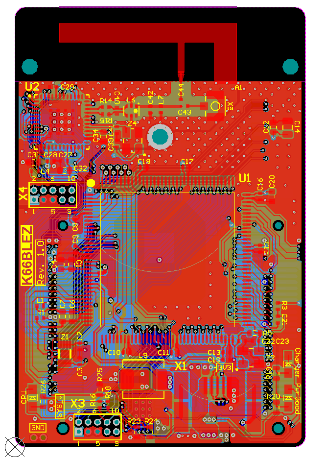 (Click to enlarge) | The built-in antenna can be replaced with a remote soldered to the board connector type UMC. Dimensional drawing of the module.  (Click to enlarge) |
| Created a schematic and constructive (3D) component of the module for the Altium Designer development environment. Module component files can be found in the repository at the link at the end of the article. 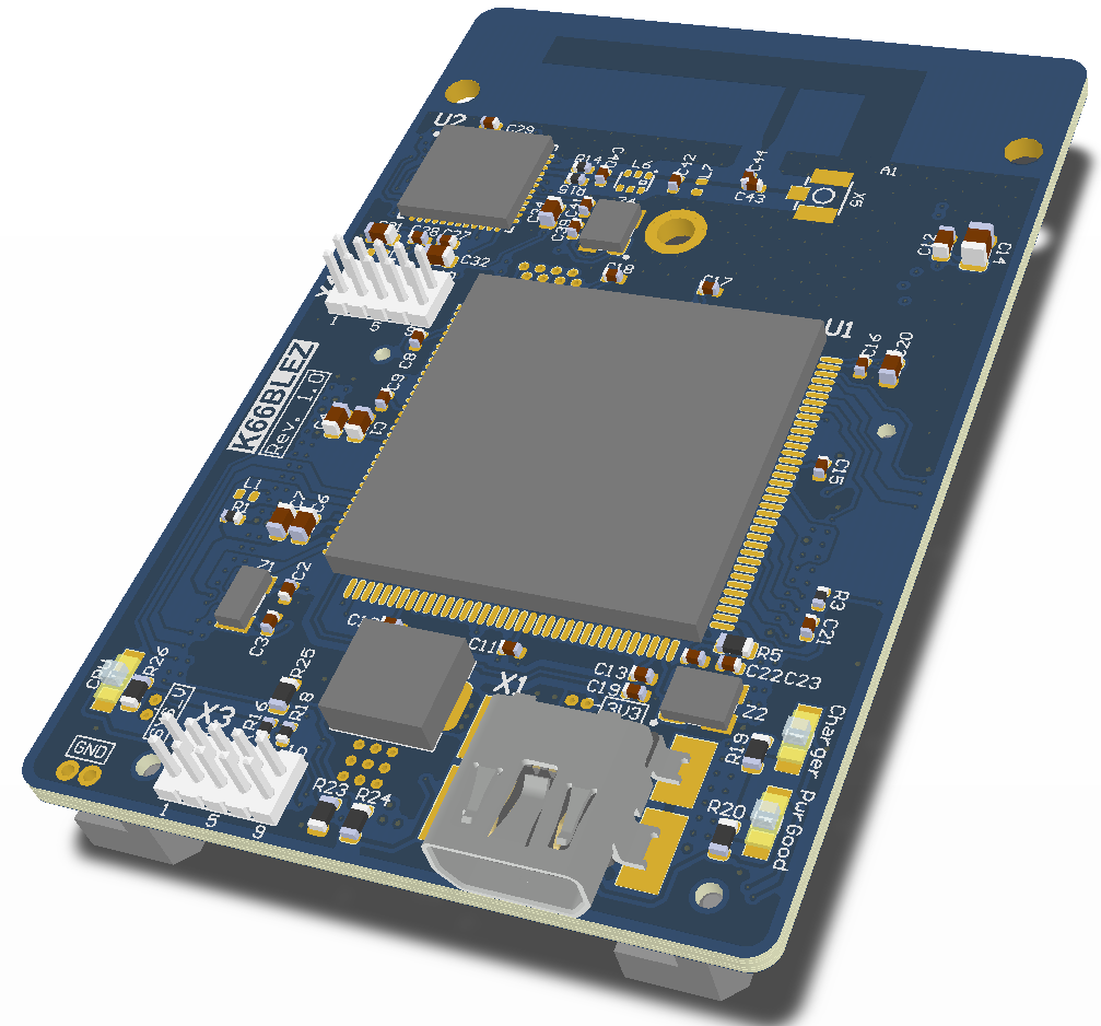 (Click to enlarge) | Representation of the module circuit element in the Altium Designer environment (Click to enlarge) |
Scheme of the module K66BLEZ1.
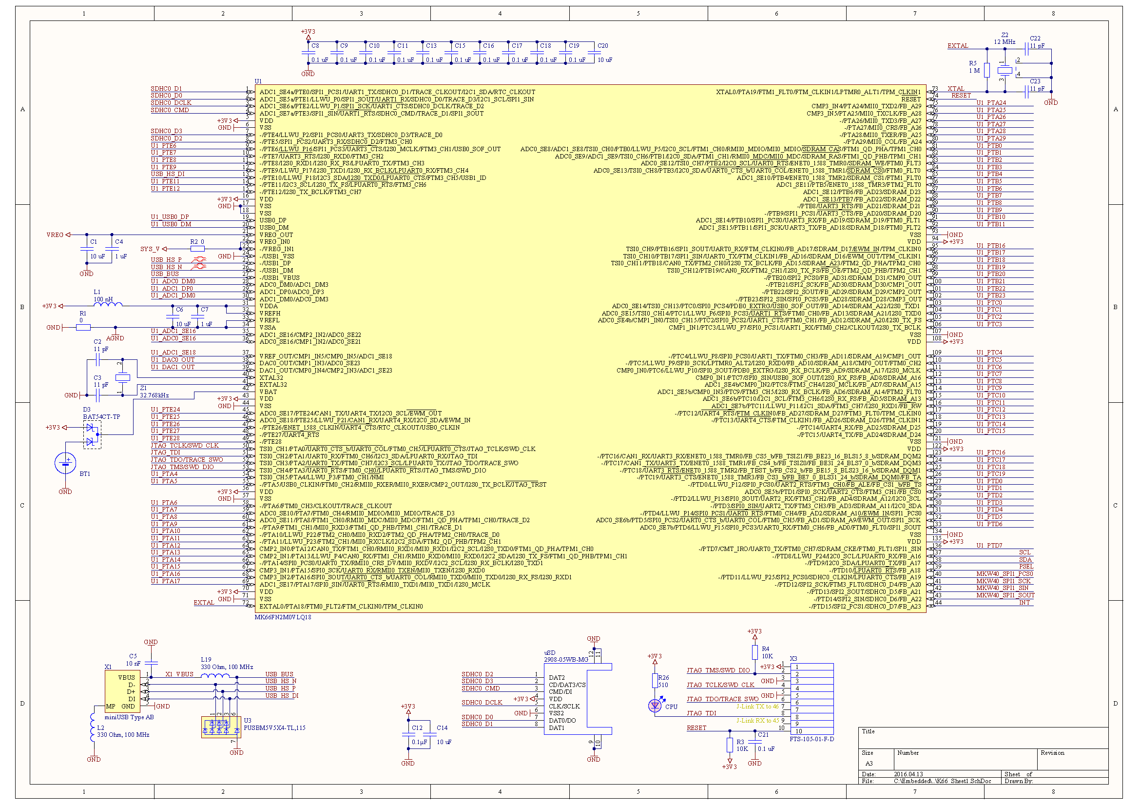
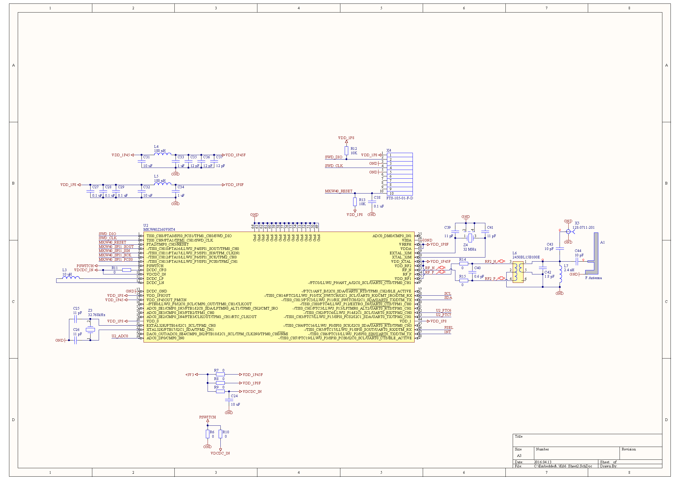

Most of the conclusions of the microcontroller MK66FN2M0VLQ18 are derived to two external connectors. The connectors are selected so that it is convenient to connect and disconnect the module from the motherboard.
Power is connected to the board either via a USB connector or via expansion connectors X6, X7. The BQ24296RGET charger chip provides a reliable autonomous charge of a lithium battery from USB with control of current, voltage and battery temperature.
The procedure for starting the board to work.
Step one. Power supply to the module.
Power is supplied by connecting the USB cable. The current consumption does not exceed 100 mA so any USB host interface of the computer is suitable. While in the microcontroller there is no program, the computer does not react to the connection of the module via USB.
But on the module the “PwrGood” LED should turn on. The “Charger” LED should flash, this indicates that the battery is not connected. LED "CPU" is serviced by software, so it also does not light up.
Step two. Connecting the JTAG / SWD adapter and checking the operability of the SWD channels.
Microcontrollers on the board have separate connectors for connecting debug adapters via the SWD interface. The K66 microcontroller allows for a 3-wire SWD connection with a SWO signal (X3 connector), and the MKW40 microcontroller allows only a 2-wire connection (X4 connector). But this does not impose restrictions on the debug adapter, and it can be the same for both microcontrollers.
I use the J-Link adapter for debugging. Debug connectors on the module with 1.27 mm pitch. Therefore, we had to make a special adapter from the standard adapter connector to the module connector as shown in the photo below.

(Click to enlarge)
Although the J-Link adapter is the best in its class, it is possible to use cheaper debuggers, such as ST-Link , for debugging.
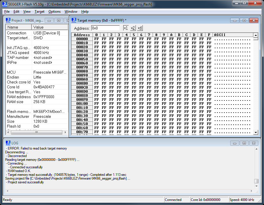
To test the performance of debugging and programming channels, I use the utility from Segger JFlash .
This utility allows you to view the status of all memory areas of the chip, test the speed of the interface, and program the flash memory of the chips.
(Click to enlarge)

(Click to enlarge)
Using JFlash, I managed to connect and check both chips on the module.
Step three. Testing the first program for the microcontroller K66
However, the first program will not be Hello Word and not even a flashing LED.
As a first test, we will immediately select an external disk emulator via USB and a video camera USB emulator .
This is possible because the module circuit repeats the scheme of the debug board FRDM-K66F.
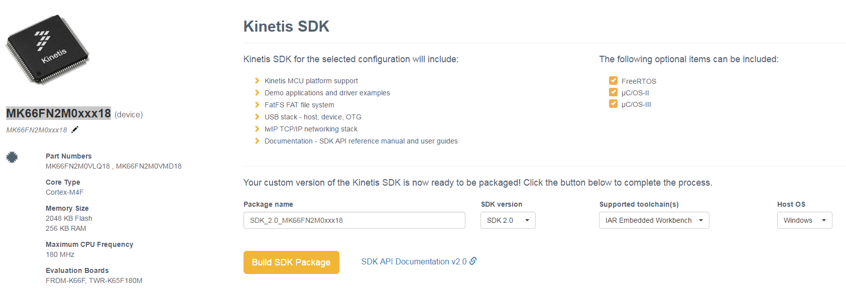
But first you had to download the SDK with examples of programs.
The SDK is created for the board with a special online tool on NXP.com at http://kex.freescale.com/en/summary?cas_auth=1 (you will have to register on the site for this)
In the dialogue, select the microcontroller MK66FN2M0xxx18
The dialog box will look like below:
(Click to enlarge)
At once it is necessary to determine the development environment in which the SDK will be compiled. You can choose one of the list or all at once. The list includes both commercial IDEs and freeware:

I traditionally choose IAR . My recent research on compiler choice has once again shown that IAR is still out of competition, at least for ARM Cortex-M4 .
An SDK will be created with embedded sample applications and peripheral tests for the frdmk66f and twrk65f180m boards . Practically all the examples for the frdmk66f board are also suitable for our K66BLEZ1 board. Since the quartz resonators of these boards have the same frequency and the K66BLEZ1 matches the connection of the SD card and the USB HS interface.
Examples were tested: usb _ device _ cdc _ vcom , usb _ device _ cdc _ vcom _ lite , usb _ device _ msc _ sdcard , usb _ device _ video _ virtual _ camera .
The write to the SD card in the usb _ device _ msc _ sdcard example was rather low - 200 KB / s., Reading - 1 MB / s.
In the usb _ device _ video _ virtual _ camera example, PotPlayer x64 was used to view the video. A screenshot of the video embedded in the microcontroller is shown below.

(Click to enlarge)
Total
The board showed reliable performance. The USB interface was tested at full speed of 480 Mbps. All USB drivers on the PC side are also working. Debugging mechanisms of both processors work without failures including SWD, tracing and virtual COM port. Further testing will be continued in the following articles.
All materials related to this project are stored here - https://github.com/Indemsys/K66BLEZ1
Source: https://habr.com/ru/post/392839/
All Articles