Maintaining servo position: slave control vs stepping mode
After the publication of the previous articles on vector control of electric motors, there were many questions about the positional drive - how can the actuator work out a given position? How does a servo drive in modern machines work, how to use a signal from a position sensor, how does a stepper drive differ from a servo drive with subordinate regulation? Let's show everything in the form of pictures and video.
So what is a servo with a position loop? First look at this. So that you can see the graphics on the background I advise you to watch in full screen.
Three-loop management structure
The control system seeks to maintain the specified position of the rotor shaft. I make a disturbing effect, I pull the rotor away from a given position, but after releasing the shaft, it instantly returns to the task again. Even if it is “twisted” by several turns, the control system will unscrew these several turns back, and with very good dynamics - such that the movement does not even have time to get into the frames of the video. The background of the drive is visible in the background: the motor current is shown in red (proportional to the moment), the current position of the rotor shaft is shown in green, and the position reference is displayed in yellow. The maximum allowed moment (current) of the engine in this experiment was limited to three times the maximum, at full, I could not hold it so easily.
How does such a control system work? This is a classic three-loop system of subordinate regulation with successive correction, shown in Fig.1.
')
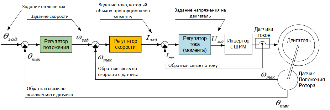
Figure 1. Three-subordinate regulation system
Why subordinate? Because each nested contour "obeys" the task of the superior. There are three circuits in the system, starting from internal: current (moment) contour, speed contour (rotational speed), position contour. Accordingly, each circuit with its regulator maintains its value at a given level. In this case, a PI controller for currents, a P controller for speed, and a PID controller for position were used. No magic like fuzzy logic, linear-quadratic regulators and other things.
Why precisely three circuits and precisely such? I will try to explain, as usual, "on the fingers." If we want to adjust the position, then the best that we can control for this is the speed (rotational speed), because it is the speed that directly affects the change in position (the speed is a derivative of the position), and all other values (current, voltage and other) affect the situation in a more complex way, more difficult to regulate. Further, if we now want to control the speed, then the best that we can control is the motor torque, since the torque determines the acceleration of the drive, and it is also the simplest mathematical law associated with speed. Since for a motor moment is a current (for a DC motor this is true in an explicit form, and for AC motors it is true for moment-forming current in vector control), to control the moment you need to control the voltage on the inverter of the converter because the current and voltage connected in the first approximation through a simple differential equation.
If any inner contour is omitted, then ... the position will be regulated, but it will be adjusted poorly, not with the same speed as in a three-loop system. If you throw out, for example, the current loop, forcing the speed controller to act directly on the voltage of the inverter, then the drive torque (current) will remain uncontrolled - it will change as it wants, the transients will be flowed to gravity. Unfortunately, some arduinovody make the structure shown in Fig.2.
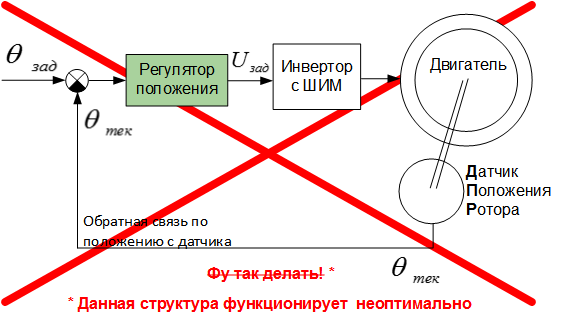
Fig.2. How not to adjust the position of the drive.
Such a structure works disgustingly (slowly and swinging), although somehow it works - the PI controller will pull everything out.
Direct and alternating current: what is the difference for the position loop?
What is the difference in position control for DC motors and for AC motors? In the way of maintaining the moment. In the DC motor, it is enough to put one current regulator, which affects the voltage of the armature winding - you get the regulation of the moment. In AC motors (for example, a synchronous machine with permanent magnets and an induction motor), vector control will have to be applied. What it is and how it works has already been discussed in detail in the articles “ Vector control of an electric motor“ on fingers ” and Vector control for an asynchronous electric motor“ on fingers ” . As with the DC motor, vector control allows you to adjust the torque on the motor. Further, the same speed and position regulators are “hung” from above. The final performance of the position loop does not depend on the type of engine (only minor nuances change).
Step mode
For synchronous machines with permanent magnets, there is one more variant of position processing - the so-called “stepping” mode of operation. Engines optimized for it, respectively, are called stepper. Not all stepper motors are synchronous machines with magnets, but most of them are just that (there are also inductor type shags). How it works? The motor is simply supplied with a constant current in the desired phases. And that's all. The rotor under the action of the "magnetic spring" itself rises in a position corresponding to the current. If you need to change the position of the shaft, then the current vector needs to be rotated - it depends smoothly or discretely on the “driver” of the stepping motor (with or without microstep). About how the synchronous motor works, and where there in it the magnetic spring has already been described in the article .
Stepping mode is good because besides the current loop, it does not need anything - neither a position sensor, nor even a microcontroller. The control system for such a mode is assembled from three and a half ICs and is used in all CNC machines of the amateur (and not so) level. What are the cons? The position is also supported disgusting. The engine itself maintains the position in this mode - a direct current is supplied to the stator, and the rotor tends to stand in the appropriate position. One can imagine two rectangular magnets on one axis, passing through their middle (Fig. 3). We control with one magnet (stator current), and the second - the rotor, dangles by itself and tends to turn according to the first one, parallel to it.
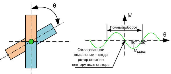
Fig. 3. Step mode synchronous machine
The moment on the rotor in this mode varies according to the sine law of the misalignment angle between the two magnets. In the coordinated position, the moment is zero (no load acts on the rotor), at 90 degrees (magnets are perpendicular) the motor moment is maximum and tends to turn the rotor to the coordinated position. And the amplitude of this sine of moment variation depends on the magnitude of the supplied current.
The number of pairs of poles
To improve the accuracy of maintaining the position in the stepping mode, constructively increase the number of pole pairs at the engine. If the pair of poles is one, then the motor corresponds to the two magnets in fig. 3 - the rotor can hang up to a quarter of a turn back and forth from a given position. When the number of pole pairs increases, the number of north-south alternations increases, both in the rotor magnets and in the stator windings. Here is a picture showing an engine with one pair of poles and two:

Fig.4. One pair of poles vs two pairs of poles.
If you try to rotate such an engine with two pairs of poles with a direct current applied to the phases, then the torque on the rotor will increase to a maximum not in a quarter turn (90 degrees, as in one pair of poles), but in the eighth part of turn (45 mechanical degrees). The engine will have two stable rotor positions on a mechanical revolution. For convenience, the description of the processes in the engine introduces the concept of "electric revolution" - how much it is necessary to rotate the rotor so that the magnets of the rotor of one pole stand in place of the same from the other pole, i.e. to make one "step". Then they say that the rotor has turned by 360 electrical degrees, and in order to translate it into mechanical ones, it is necessary to divide by the number of pole pairs. On the electric circuit, the behavior of all motors in the control plan is the same, regardless of the number of pole pairs. An increase in the number of pairs of poles creates only a kind of "electric gearbox" - you can take a car with one pair of poles and put on a fourfold reduction gear, or you can take a car with four pairs of poles and get, roughly speaking, the same thing.
Stepping mode vs subordinate regulation: theory
For stepper motors, the number of pole pairs is very large — 50, 100, and more. In this case, the natural abilities to maintain the position are very good - if you ensure that the load moment never exceeds the maximum motor moment, then the position without any position sensors will be maintained with an accuracy (± 360 / (number_Par_Polarity * 4)) mechanical degrees. True, the price for this is a strong deterioration in engine performance in terms of weight and size and efficiency. If we compare a stepper motor with a hundred pairs of poles of the same size and a synchronous motor with a small number of pole pairs, then the long-term power of the stepper will be several times smaller. And because of the increase in the number of pairs of poles, the step-makers have a problem with working at high rotational frequencies. The frequency of the current in them has to be supplied in number_par_polarities times greater than in a “normal” synchronous machine, which gives current frequencies of the order of a kilohertz and more - there are huge losses on the remagnetization of iron, and not every control system can.
In addition, the footsteps do not provide good acceleration and deceleration dynamics, since during acceleration the engine must overcome two points: the load moment, as well as the dynamic moment for the acceleration of the swing weight and the working body. And if the sum of all moments exceeds the maximum motor moment, it will skip a step, which is unacceptable for the CNC. Therefore, the step-drivers accelerate and brake necessarily smoothly, with a large margin between the total torque on the shaft and the maximum torque of the engine, so as not to miss the steps.
It is also worth noting that in the stepping mode, when a load is applied to the rotor, it will always yield and deviate from a given position at a certain angle, whatever the current applied to the motor. Also, with a sudden loss of load, fluctuations are possible - the rotor on a magnetic spring will swing back and forth. If you are not lucky with the load, and it will be pulsed, then it can coincide with the internal oscillation frequency of the rotor, swing it, after which the rotor will fall out of synchronicity - the engine will “skip a step”.
What to do if to solve the problem it is necessary to maintain the position well and get a dynamic, high-speed drive? Do not use shagoviki! And use an “ordinary” synchronous machine with a small number of pole pairs as a servomotor, install a position sensor and build a three-loop control system. There are no “steps” in the vector control system anymore - there is nothing to be lost. In stepping mode, a large current is always required to pass through the motor, and in vector mode with a three-loop control structure, the current flows only when a load is applied to the shaft. The accuracy of maintaining the position in the subordinate control system is most often determined by the accuracy of the rotor position sensor. The more accurate the sensor, the better the position contour is obtained. And modern position sensors are very accurate - hundreds of thousands of tags per mechanical revolution. It is orders of magnitude better than the stepping motors with the strongest step crushing.
Step mode vs subordinate regulation: practice
And now let's see in practice all of the above. It is necessary to describe the stand with which I work. There is a lot of technical information, I'll hide it under the spoiler.
Stand for experiences
This is a VectorCARD 192101 debug kit, produced by our company, which I dragged home for the weekend to take off beautiful experiments and write an article.
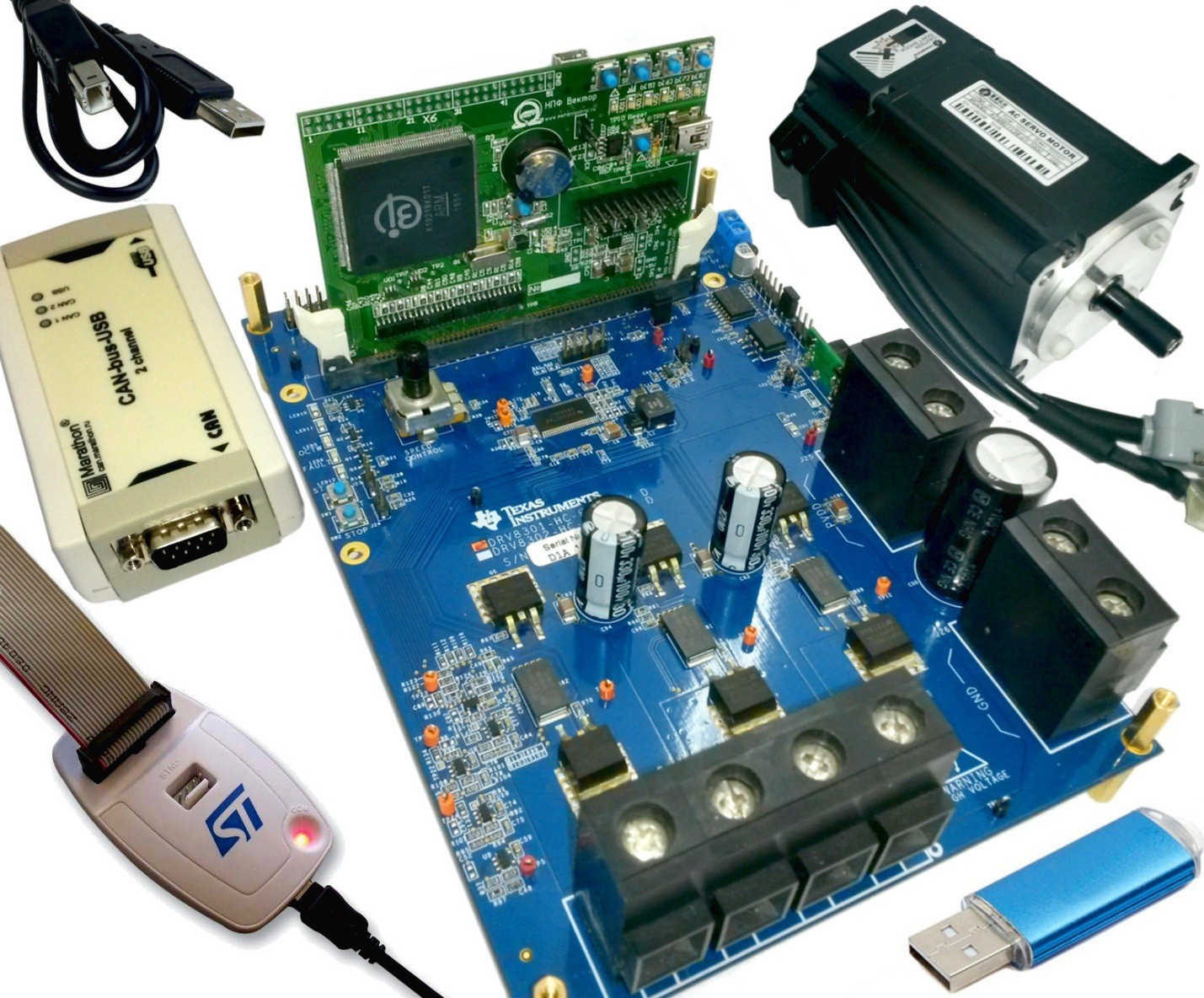
Fig. 5. VectorCARD 192101 Motor Control Debug Kit
Servomotor - Leadshine ACM601V36-1000. Three-phase synchronous machine with permanent magnets per 100W, 4 pairs of poles, supply voltage 36V, rated current 4A, peak 11A. The position sensor is a built-in incremental encoder for 1000 periods of a quadrature signal (or, equivalently, 4000 fronts (marks) on two channels A and B in total).
The inverter is a six-key field-effect transistor from the DRV8301-HC-EVM Texas Instruments kit.
Controller - VectorCARD K1921VK01T debug board on the domestic K1921VK01T microcontroller of NIIET OJSC (ARM Cortex-M4F, 100 MHz ) .
The general structure of the vector three-loop subordinate regulation, created by software, is shown in Fig. 6
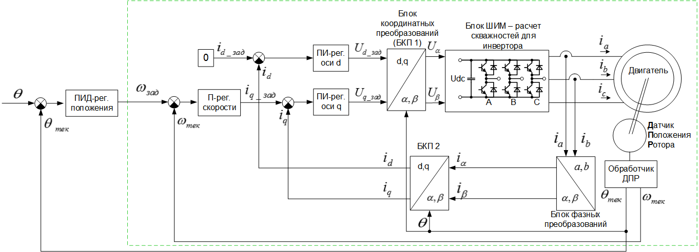
Fig. 6. Three-loop structure with vector control of a synchronous motor: current (moment) contour, speed, position.
If this structure seems terrible to someone, then everything that was circled in a green frame was completely dismantled in the article Vector control of the electric motor “on the fingers” . By its principle, the structure is no different from the structure of fig. one.
The PWM frequency is set to 20 kHz, the calculation frequency of the control structure (all three circuits) is 10 kHz. Current sensors - shunt type, installed in series with the lower keys of the inverter. The resources of the microcontroller for computing performance are loaded by a little more than half.
Fig. 5. VectorCARD 192101 Motor Control Debug Kit
Servomotor - Leadshine ACM601V36-1000. Three-phase synchronous machine with permanent magnets per 100W, 4 pairs of poles, supply voltage 36V, rated current 4A, peak 11A. The position sensor is a built-in incremental encoder for 1000 periods of a quadrature signal (or, equivalently, 4000 fronts (marks) on two channels A and B in total).
The inverter is a six-key field-effect transistor from the DRV8301-HC-EVM Texas Instruments kit.
Controller - VectorCARD K1921VK01T debug board on the domestic K1921VK01T microcontroller of NIIET OJSC (ARM Cortex-M4F, 100 MHz ) .
The general structure of the vector three-loop subordinate regulation, created by software, is shown in Fig. 6
Fig. 6. Three-loop structure with vector control of a synchronous motor: current (moment) contour, speed, position.
If this structure seems terrible to someone, then everything that was circled in a green frame was completely dismantled in the article Vector control of the electric motor “on the fingers” . By its principle, the structure is no different from the structure of fig. one.
The PWM frequency is set to 20 kHz, the calculation frequency of the control structure (all three circuits) is 10 kHz. Current sensors - shunt type, installed in series with the lower keys of the inverter. The resources of the microcontroller for computing performance are loaded by a little more than half.
Stepping mode vs sub-regulation: comparison in static mode
First, we compare the step mode of operation and the three-loop system of subordinate regulation with vector control "in statics". We assign the same position of the rotor, and then we will smoothly increase the load torque on the shaft. In the stepping mode of operation, we will provide the rated current 4A, and in the vector mode of operation we set the current limit to 4A. What do we expect to see?
In the stepping mode of operation, the current will be constant both in phase and amplitude, and the rotor position must “bend” on the magnetic spring under load. Since the number of pole pairs is 4, the maximum of the moment should be reached with a deviation of 360/4/4 = 22.5 mechanical degrees from the initial agreed position.
What will happen in the three-loop control system? The position controller in this experiment is PID (proportional - integral - differential). The key letter here is “AND” - it has an integral component. This means that as long as there is at least some mismatch between a given position and the current one, the regulator integrator will integrate and increase its output until the error reaches zero. This means that if the shaft is loaded slowly, so that the integrator has time to integrate and compensate for the error (ie, in static mode), the shaft will be in the same position “dead”. But when the current stock (moment) of the drive is exhausted (the task for the current reaches the 4A limit), the drive will immediately begin to yield and deviate from the task (nevertheless, it will always pull with the maximum moment towards the task).
To track the current position of the rotor shaft, it is convenient to monitor the error signal from the position sensor (the difference between the reference and the current position), as well as the stator current. When conducting an experiment, the waveform with this data will be visible in the background. To observe the current load moment in the experiment, a high-precision specialized dynamometer was used, which I took from the drawer of the kitchen table. Here, in fact, is the experience itself (for something to be seen - full screen!):
The video confirms this. In the vector three-loop control system, the rotor stood motionless until I “chose” the available 4A current, and then the rotor began to deviate. In the open-circuit structure with a direct current, the rotor easily yielded to the external moment. Since the number of pole pairs of this engine is 4, the rotor deviated by more than 20 degrees from the reference.
Stepping mode vs subordinate regulation: comparison in dynamics
Everything becomes more interesting in dynamics. What if you apply a pulse, shock load? Here is the competition of two fundamentally different systems. In a vector control system, the speed depends directly on the speed of the three-loop control structure. The harder the regulators are set up, the faster the frequency of the calculation of the structure, the more accurate and faster the sensors, the better the response to the disturbance in the dynamics will be. In stepping mode, the control system "rests." She created a current vector - that's all she needs. The entire response to the disturbing effect is provided by the engine itself. The moment on the shaft with the deviation of the rotor shaft occurs "instantly", since it is, in fact, the interaction of two magnets. But the moment increases in proportion to the sine of the electric angle of deflection, which means that such a system will have a certain rigidity. In general, this is the usual "magnetic spring." Comparison over time is a very good demonstration experience for a three-loop control system. If it is slow, then it will not be able to show the result better than an open structure. Yes, in statics, a three-loop structure can choose an error in the zero position as an integral part of the regulator, but in dynamics it can even “sow” stronger than the usual stepping mode of operation. Check?
To carry out this experience, I used a dimensional load, which I found in my cabinet with tools, as well as a thread tied to a rod, which has a cantilever fastening on the engine coupling. Dropping the load down from a fixed height, we get a shock impulse load on the rotor shaft. You can observe how much the rotor shaft deviates from the task at the moment of impact. Here is a video of the experiment:
Initially, the stepping mode of operation with a fixed current vector is enabled. I show how the rotor bends under the influence of the load moment, how, by overcoming the load moment, it is possible to jump to another fixed position. Then I conduct an experiment on the discharge of cargo. Further, the same for the three-loop control structure. Have you noticed how much less rotor shaft has deviated on video in a three-loop control system? Or maybe more? Me not.
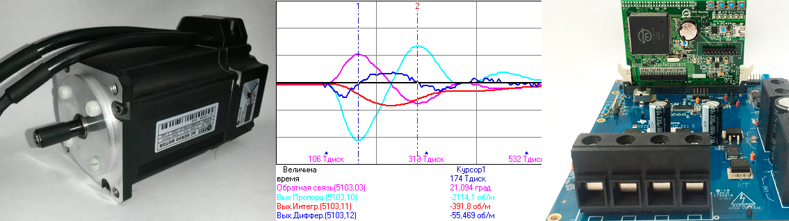
If a similar video was taken by the Discovery Channel, they would definitely install a high-speed camera for beautiful comparative shots. However, we have a tool more precisely - the rotor position sensor and the microcontroller. You just need to remove the oscillogram of the position processing error at the time of application of the pulse load. How this is done is described in detail in the article Methods for debugging software of microcontrollers in an electric drive . In short, the microcontroller records the waveform points to an array at a specific event, and then the waveform is downloaded to a computer and displayed. I set the oscillogram shutdown trigger in the controller's software when the error in the position is greater than a certain setpoint, having written a couple of lines of C code for this. After that, on the computer, I got the following waveform for step mode operation with a current of 5A:
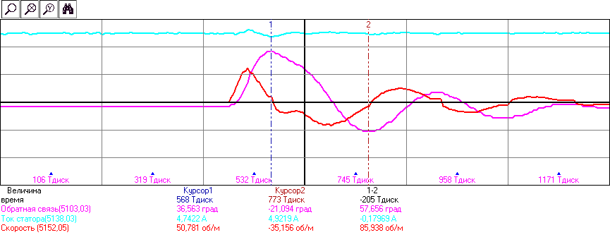
Fig. 7. Oscillogram of response to impulse load increase in the “stepping” mode of operation - a vector of current of a fixed amplitude and phase is applied to the motor. Violet shows the deviation of the rotor from a predetermined position in electrical degrees (to go to mechanical divide by 4), blue shows the amplitude of the stator current, red indicates the shaft rotation frequency. In one cell along the time axis, 21 milliseconds.
I added three control system variables to the oscilloscope: position error, stator current, shaft rotation frequency. It is seen from the oscillogram that the stator current remained constant and equal to 5A, the shock load introduced only a small perturbation into it (due to the EMF of the rotating motor). But the position jumped much. The maximum deviation of the shaft position from the reference was 36 electrical degrees (or 9 mechanical). There is a damped oscillatory mode of the rotor after impact. I conducted several such experiments, making sure of repeatability. All the oscillograms turned out to be similar - it’s good that if you have the right tools, you can spend 5-10 seconds to conduct an experiment and get an oscillogram (as inserted in the article).
Now let's see what the three-loop control structure will show (Fig. 8). Previously, I set up all the regulators in it for the average speed.
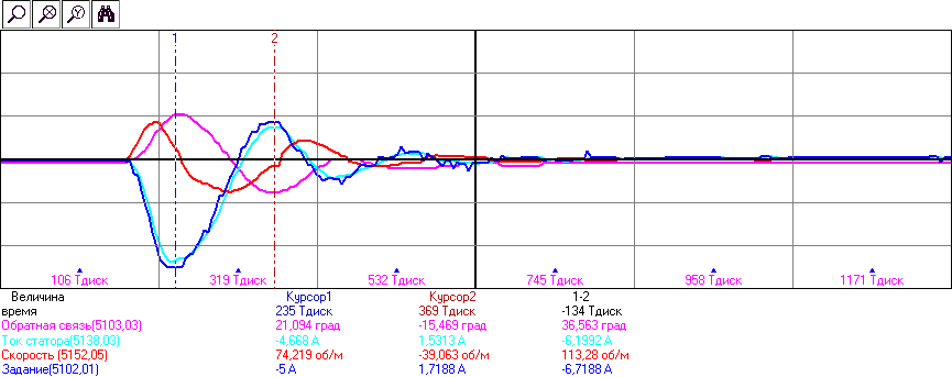
Fig. 8. The oscillogram of the response to the pulse load surge with a three-loop system of subordinate regulation. Violet shows the deviation of the rotor from a predetermined position in electrical degrees (to go into mechanical divide by 4), blue shows the current current of the stator along the q axis (moment-forming current), blue indicates its task, and red indicates the current speed. In one cell along the time axis, 21 milliseconds.
Here the process is more interesting. In addition, in fact, the provisions, I added to the oscilloscope still any values that show the work of a subordinate regulation. At the initial moment of time everything is zero: the error is zero, the speed, the stator current and its task. There is no force acting on the rotor, it rests due to its friction force. But the tape at that moment is inexorably flying down, the rope is unwinding ... At a certain moment, the length of the thread is selected, the load hits the shaft, the position begins to change, the error (position controller feedback) shoots up, along with the shaft speed. In response, the three-loop system dramatically increases the moment on the drive, trying to return it to its original position. After five milliseconds after the impact, the torque on the engine reaches the maximum allowed (current 5A), after which the position reluctantly begins to change in the opposite direction, the speed changes sign. Having flown a zero point and having made a couple of oscillations, the system comes to the task.
You can see how the task for the stator current (blue) is slightly ahead of the current value (blue), but the delay is less than a millisecond, which indicates a high speed of the current loop. However, in the current task some “fluffiness” and “needles” are visible, especially at the end of the transition process. What is it and where is it from? Let's look at what the position controller gives out in this process - the output of its proportional, integral and differential components. I drop the tape again, here they are:
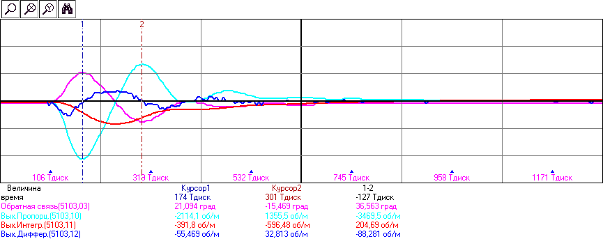
Fig. 9. The oscillogram of the response to the pulse load surge with a three-loop system of subordinate regulation. Violet shows the deviation of the rotor from a predetermined position in electrical degrees (to go into mechanical divide by 4), blue - the output of the proportional part of the PID position controller, red - integral, blue - the differential part. In one cell along the time axis, 21 milliseconds.
See how all three parts of the PID controller work out the transition process. The oscillogram is like a textbook, but this one is live, real and fresh, only from the engine. The output of the proportional part is directly proportional to the error. The integral part is the integral of the error, see how he integrated “down” from the first large oscillation and then reluctantly comes to zero. The differential part is the derivative of the error. But since the position sensor is incremental and only for 1000 labels, the change of each label is an event. Therefore, the position for the control system changes discretely, irregularly, and hence the derivative of such a change will be “needle-like”. Or even pulsed, rectangular, noisy - which is what we see.
But wait ... The derivative of position is speed! Scroll higher to pic. 8 and compare that speed graph with the graph of the differential part of Fig.9. The same, but no noise! Because the rotation speed of the incremental encoder processing module is determined more competently - by the hardware part of the microcontroller, which measures the time between the sensor marks. The same "derivative" of the position, but more correctly measured.
What is moral? Not all components of the regulator are equally useful. What the differential component of a position controller does is theoretically supposed to be made by the subordinate speed loop. If I needed it for better tuning, it only means that I didn’t adjust the intermediate speed loop.
Oh yes. What did we start there? With a position error. In the open mode, the error was 36 electrical degrees (9 mechanical), and in the three-loop subordinate control system with this setting of the regulators, it is 21 electrical degrees (5.2 mechanical). Better, yes. Is it even better? Let's take another position control coefficients. I increase everything - Kp, Ki, Kd times in one and a half. We look:
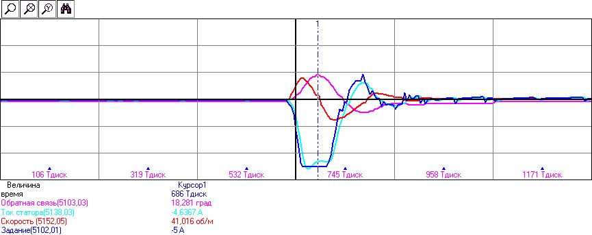
Fig. 10. The oscillogram of the response to the pulse load surge with a three-loop system of subordinate regulation. The coefficients of the position controller are increased by one and a half times.
The error has decreased, yes ... 18 electrical degrees. But what do we see? The control system almost immediately rested on the current limit. She would like to apply a current greater than 5A, but I put the restriction 5. Why? To honestly compare with the open-loop control system, which also had a current of 5A. Only now it turned out dishonest: the vector control system creates a current only when it needs it (when it is necessary to realize the moment), and an open system “drives” the given current always. From the point of view of heating and losses for the engine, a vector control system is much more preferable.
Let the vector system "to succumb" to the current? At least for a short time. According to the passport, the engine allows 11A. Solve 7A to evaluate the result.
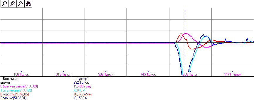
Fig. 11. The oscillogram of the response to the pulse load surge with a three-loop system of subordinate regulation. The current limit is raised from 5A to 7A.
An error of only 15 electrical degrees! This is 2.5 times less than in the open-loop control system.But look, what is there at the end of the chart? "Needles" in the task of current ... and they continue and continue, what I hear acoustically - the engine "rings". This is called self-oscillation - too much pulled up the factors of the regulator.
Closed loops and their noises
So we got to the specific question of the quality of any control system, which is sometimes no less important than the accuracy of maintaining the regulated parameter itself - noise. Is it permissible for the engine to “rustle” in a closed control system? It depends on how much it makes noise and what makes it noise. I have prepared a video that shows the various noises that can be generated in different circuits of the subordinate regulation system. To do this, I fixed the microphone in direct contact with the engine - at a distance of sound from this engine is almost inaudible. Although it depends on the engine - different engines "sound" differently.
At the beginning of the video shows the noise from the current loop. Only the current loop with two current regulators was switched on. A noise appeared in the engine, which my colleague compared to the noise from a pipe through which water flows. It looks like a "white" noise. This noise is generated due to noise measurements of phase currents. Due to the relatively large proportional component (necessary for the required speed), the current regulators catch all small fluctuations of the current measurement and amplify them, passing the inverter to the voltage command. Those.Initially, the current in the engine is even and not noisy, but its measurement makes noise, current regulators try to compensate for it, “pull” the inverter voltage, thereby causing the actual current in the engine to “make noise”. On the oscillogram you can see it like this:
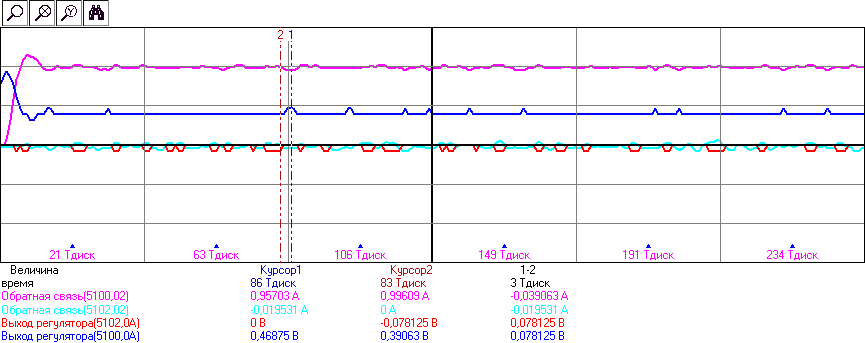
Fig. 12. Oscillogram of the transition process of the task jump (1A) of current regulators and their subsequent “noise”. Feedback is shown on current regulators (signal from the ADC) and the output of the regulators fed to the inverter. In one cell along the time axis 4.2ms.
The oscillogram shows not only noise, but also the transition process of current regulators upon switching on. The current is processed in less than 1 ms, and the transition process is close to tuning to the technical optimum. Noise in measuring current of the order of + -0.02A leads to a change in the output voltage by 20% from the current, which is heard as noise. If regulators are slowed down 10 times, you can get the following picture:
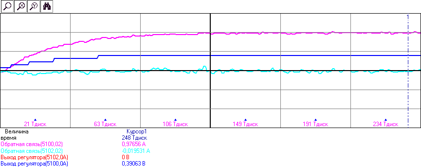
Fig. 13. The oscillogram of the transient process of the jump of the task (1A) of current regulators with Kp and Ki lowered 10 times in relation to the tuning for the technical optimum. In one cell along the time axis 4.2ms.
The current regulators are soft and quiet, like cotton, and they are absolutely uninteresting to respond to some kind of noise in the analog channel - as, indeed, on their own task ...
Next, the video shows the various sounds from the position controller. There are many experiences, I will show the last case - self-oscillations with an excessively high Kp positioner. Since the position sensor is incremental, with a large Kp, changing the position by just one notch causes the “mad” regulator to be very nervous, throwing up the task on the speed loop, and, accordingly, on the current. Something like this:
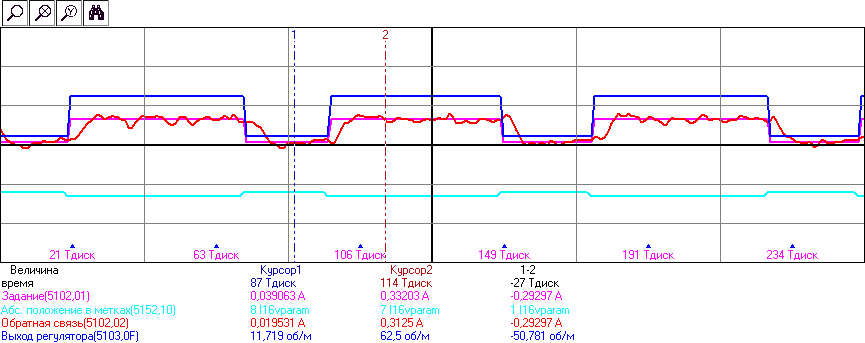
Fig. 14. Self-oscillations of the position contour with an excessively high Kn. Violet and red shows the moment-forming current of the stator (reference and actual), blue indicates the position from the encoder in the marks (increments), blue indicates the output of the position controller (reference to the speed contour).
It can be seen that when changing the position by just one label (one “tick” of the position sensor), the control system pushes the current command to 0.3A. This is a considerable moment, given the nominal value of the engine 5A, which leads to the beginning of the movement and, accordingly, fluctuations. The video shows how “scary” auto-oscillations sound, although the position jumps on one innocuous tag back and forth.
In this regard, a philosophical question arises: which vibrations and noises are terrible, and which ones should not be paid attention to? It all depends on the object - where the servo is used. If this is a three-coordinate machine with a gearbox and backlash, a welding arm or a high-speed servo drive of some steering mechanism, then the “ringing” is not so bad. In such applications, only acoustic noise can cause dissatisfaction, but hardly anything of the video shown in the video will affect the technical process. But if this is a direct drive for positioning any substrates in a silicon factory or if it is a direct drive for a microscope, then there is no noise at all “from the word”. Not that the squeaks of the position loop from the encoder, but even that barely audible noise from the current loop can already be a problem.Because all this is transmitted to the working body and will lead to a violation of the process.
Yes, I must say that all those sounds that are shown in the video are not just sounds. If you grab the shaft, they are all felt, and very well. Human fingers are very sensitive - much better than many sensors. There is even that “flowing water” noise from current regulators. Just like from the water pipe. Therefore, for servo tasks that interact with a person, noise and vibrations are also undesirable. Imagine an airplane simulator with a tilting cockpit, where the drives under it crunch and moan.
How to deal with noises? Well, with the contour of the position is more or less clear - you need to put a more accurate sensor. The encoder of these experiments on 1000 tags is a “chuckles for laughter” sensor in the field of high-precision servo drive. There, if they put the encoder, then the order of hundreds of thousands of labels. And more often put an analog position sensor, which outputs a sine / cosine signal. Using a good ADC and oversampling (measuring much more often than necessary, and then averaging the result), you can get an order of magnitude more accuracy than the encoder.
What to do with the ADC noise in the current loop? First, look for the source of the noise. In this drive, the noise source was found - this is DC / DC, which makes an instrument 5V from the input power supply and is installed on the inverter board. The layout of the board is not entirely successful, and the DC / DC “fonite” to all nearby board tracks. The very same ADC of the microcontroller is much less noisy than the noise from this DC / DC. Secondly, you can use the same oversampling, if the performance of the ADC allows it. Thirdly, you need to choose the right measurement range. I worked with the engine at 5A from the converter at 60A. Accordingly, the full range of ADC current measurement is also close to 60A. If the range were 20A, then the same noise on the analog channel after conversion to amps would be three times less.
But the noise from the ADC is not all. I did not show in the video one of the main noises, which is not audible - the noise from PWM. The frequency of the PWM in these experiments was set equal to 20 kHz - on the border of audibility. But this does not mean that these vibrations are not transmitted to the rotor shaft. It is necessary to measure the current ripple in the motor, caused by the given PWM frequency, recalculate it at the time, and then it can be estimated whether it “passes” to the shaft or not. Figure 15 shows the ripple current in the motor phase, measured by an external sensor and an oscilloscope.
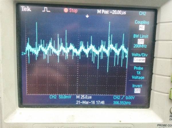
Fig. 15. Current ripple in the motor phase at a PWM frequency of 20 kHz. The magnitude of the pulsations is 0.3A.
Ripple current in 0.3A is quite significant. Rather, it would be significant if we were going to position silicon wafers in the Intel factory with this drive. Fortunately, it is not for such types of engines that it is shining and you can forget about the problem. But what if you need to make a more serious drive? For starters, you can increase the frequency of PWM. Modern power field-effect transistors can provide switching frequencies up to 500 kHz. However, there are ... three problems.
The first problem is that with an increase in the PWM frequency, the influence of the so-called “dead time” increases (some call it a non-current pause, but this is wrong - the current flows there). This is the time when the lower transistor of the inverter has already turned off, and the upper has not turned on yet (and vice versa). This time is the same for one type of transistors, and as a percentage of the PWM period, it becomes more and more with increasing PWM frequency. Dead time distorts the inverter output voltage by adding non-linearity to the inverter in the current controllers.
The second problem is that as the PWM frequency increases, it becomes more and more difficult to generate this same PWM microcontroller. The microcontroller makes the PWM using a hardware timer, which “ticks” by one with each clock of the microcontroller. By setting the comparison with the timer, the programmer chooses how long to open the key. What will be released in such a system with a microcontroller at 100 MHz and a PWM frequency of 500 kHz? We divide one into another, we get 200 quanta (discrete) of the setpoint. 200 voltage setting settings for PWM - this is useless “from the word at all”. For a servo, you need at least two orders of magnitude more. To do this, some manufacturers of microcontrollers are building in their products the so-called high-resolution PWM - they allow you to count the key-opening time with a time discreteness several times better than one clock cycle of the microcontroller.In this microcontroller there is such an opportunity, however, the third problem prevents the inclusion of high-resolution PWM.
The third problem is the current sensors. In the inverter used they are of a shunt type and stand in series with the lower keys of the inverter. This means that the current in the phase can be measured only at that moment in time when the lower key is open. This means that the launch of the ADC must be synchronized with the work of the PWM and take measurements strictly at the moment when the lower key is slightly opened. The problem is that transients in analog circuits do not have time to end, if the PWM frequency is very high - the current begins to be measured with an error. In general, everything is difficult ...
There is a fundamentally different way - some servo manufacturers generally refuse from PWM and make a hardware current loop either on the FPGA or even on operational amplifiers operating in linear mode and dissipating all the extra energy that PWM is designed to save. But this is a very, very different story.
findings
The requirements for servo drives are very different - someone has enough stepping mode control for a simple slow CNC machine (issue price driver + engine a couple thousand rubles), someone needs such a quality of maintaining the position that even the noise of the current circuit becomes a problem. This article “at the top” tells about some aspects of the work of the system of subordinate regulation and the quality of the work of the position outline, in order to acquaint the reader with something besides the well-known “shagovik”. The quality of operation of the servo shown in these experiments is, in fact, very mediocre, mainly due to the low resolution of the rotor position sensor. When using a sensor with good resolution, the quality of regulation increases markedly.
Advertising
These experiments were performed on the VectorCARD K1921BK01T debugging kit from NPF Vector LLC, built on the basis of the domestic motorcontrol microcontroller K1921BK01T NIIET (ARM Cortex-M4F, 100 MHz) microcontroller . The debug kit includes all the equipment shown in the video article, including the microcontroller software in source codes with this three-loop slave control system, as well as software for monitoring oscillograms of any control system variables.
Related links to my other articles.
Vector control of the electric motor "on the fingers"
Ways of debugging software microcontrollers in the drive
New domestic motor-control microcontroller K1921VK01T OJSC "NIIET"
Bonus Video
:
Source: https://habr.com/ru/post/392837/
All Articles