Wireless adapter for programming Arduino or AVR with a bootloader based on ESP8266
 A small note about the self-made adapter based on the ESP8266, which allows you to load the firmware into the microcontroller with the UART bootloader or Arduino installed.
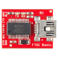
Recently, when designing devices on AVR microcontrollers, for programming I only output one 6-pin connector (not ISP) for an FTDI adapter. It allows you to download the firmware and debug on the UART after the firmware. This is exactly what was done in Arduino, the idea was borrowed from there. It's comfortable.
Meanwhile, not once had to deal with the situation when you need to load the firmware into the microcontroller, but it is already in a case that does not fit in the workplace / lies on the mezzanine / in another city / walled in the wall. In such cases, the FTDI adapter is not applicable because of the short USB lanyard and you had to dodge with a laptop. I thought about the wireless programmer. Here, the ESP8266 fits the best, because it has a UART and, in any version, has at least one GPIO, suitable for rebooting the controller and entering the programming mode.
The following topic material was found on the net:
- Programming an Arduino via WiFi with the ESP8266 - the ESP-01 type module is connected on wiring to the Arduino pro mini, then the python script is used to download the firmware
- Programando un Arduino remotamente con el módulo ESP8266 - here, as I understood it, without going into details, one of the Arduino GPIO is connected to RESET. First, the microcontroller is given the command to reload itself, and then the firmware download begins
- ESP8266-transparent-bridge - firmware for ESP8266 that makes transparent Wi-Fi from the module - a UART bridge with AT support for controlling GPIO2. The author suggests to press the reset button on the Arduino, and then launch avrdude with the parameters -c avrisp and -P net: xxxx: 23, but this allows you to automate AT. I took this firmware as the basis
Adapter specifications are as follows:
- Six-pin connector with pinout like an FTDI adapterHidden text
- Work in circuits with a microcontroller supply voltage of 3.3V or 5V, selected by jumpers
- Stable operation at speeds up to 57600 inclusive
- Reboot the microcontroller using AT commands to enter programming mode
The performance was tested on the Chinese Arduino pro mini with a stock loader and on ATmega8 with optiboot installed and speeds of 9600, 19200 and 57600. At the default speed (115200), the controller refused to flash.
For those who do not want to solder and pay
In the case of application in 3.3V-powered circuits, simply connecting the esp-01 module to the Arduino wiring (VCC -> VCC, GND ---> GND, RX ---> TX, TX ---> RX, GPIO2) ---> DTR). The board is made for ease of connection and the ability to work in circuits with a microcontroller 5V supply voltage.')
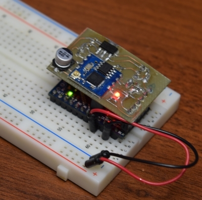
Schematic diagram and PCB

Modules of the esp-02 type are used, but the common esp-01 will also work, only the board will need to be re-routed slightly. Jumpers choose 3.3 / 5V operation mode. U1 - stabilizer converts 5V to 3.3V if necessary. R2 and R3 - divider, also for 5V mode. After the assembly, you need to install the RPOG jumper and use the same FTDI or any other UART adapter to load the ESP8266-transparent-bridge .
One-way PCB Template (SVG Vector):

If you want a negative, just open it with a text editor and replace # 000000 with #FFFFFF and vice versa.
In KiCad format on github
Microcontroller firmware
Usually, to download the firmware, you must restart the microcontroller. The FTDI adapter makes this a pulse on the DTR leg (the first one in the connector), it is connected to the RESET microcontroller through the capacitor. In our case, GPIO2 has been replaced with DTR (see UPD). To reboot the microcontroller, AT commands "+++ AT GPIO2 1" and then "+++ AT GPIO2 0" are used, which change the level to GPIO2 ESP8266. One differential is enough to reset the controller. Immediately after the reboot, the bootloader works for some time and waits for the UART firmware image, you can transfer it using the avrdude utility. Below is the script which the controller is flashing:#!/bin/bash HEXILE="firmware.hex" ADDRESS=xxxx BAUD=57600 echo "+++AT BAUD $BAUD" | nc $(ADDRESS) 23 echo "+++AT GPIO2 1" | nc $(ADDRESS) 23 echo "+++AT GPIO2 0" | nc $(ADDRESS) 23 avrdude -P net:$(ADDRESS):23 -F -U flash:w:$(HEXILE):i These commands can be included in the Makefile.
Wireless firmware can also be turned in Windows by installing the nc and avrdude utilities.
Video demonstrating the work on the example of the Chinese Arduino pro mini
UPD :
sav13 suggested using esp-link as firmware for ESP8266, it is compatible with the current adapter circuit. This firmware has several advantages compared with ESP8266-transparent-bridge, incl. WEB interface for configuration, no need to use AT commands, additional functionality, in more detail here .
Source: https://habr.com/ru/post/392833/
All Articles