Reincarnation of the "popular" board TP4056 or self-made charging for lithium at 3A
Greetings to all who looked at the light. This review, as you probably already guessed, will talk about one interesting modification of the “popular” TP4056 charging module for 3A current and a small use as homemade charging for lithium. There will be a little testing and a simple example of making charging from cheap components, so whoever is interested, you are welcome under the cat.
So, here is the very modification of the "folk" scarf:
TTH:
Equipment:
')
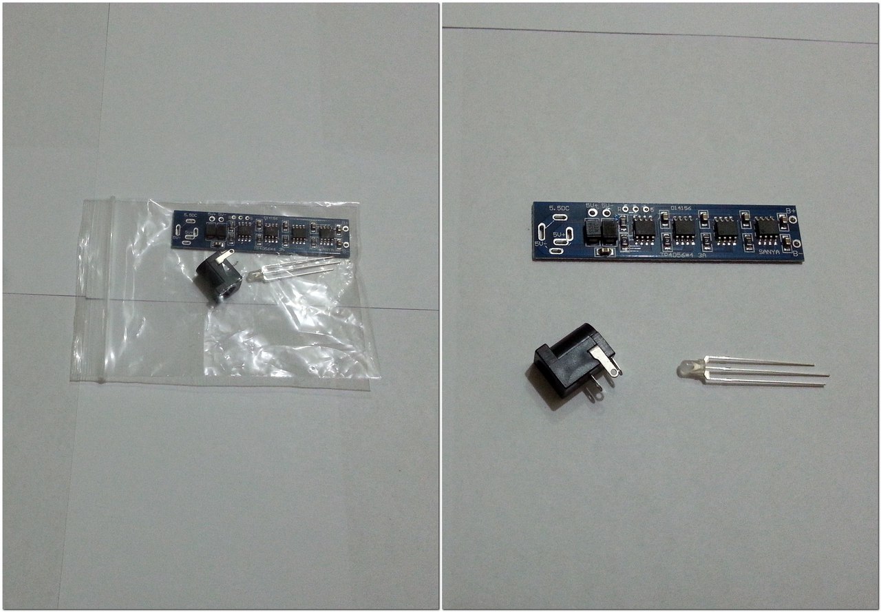
A handkerchief is delivered in the usual small package; I arrived in two or three weeks. Inside the package there was a kind of protection - two glued sheets of polyethylene foam, inside of which there was a scarf:

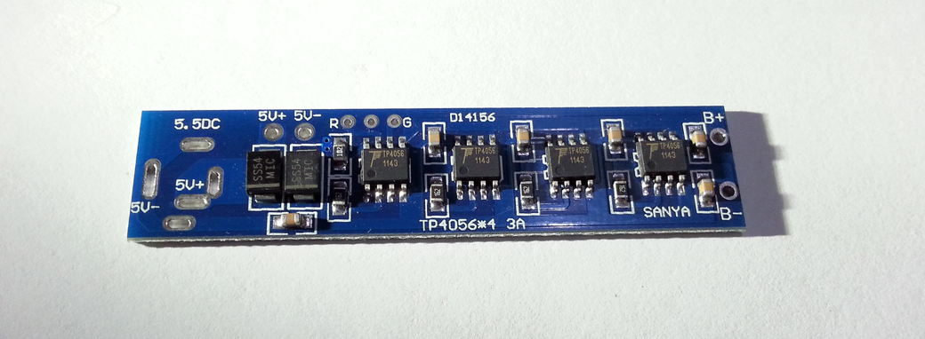
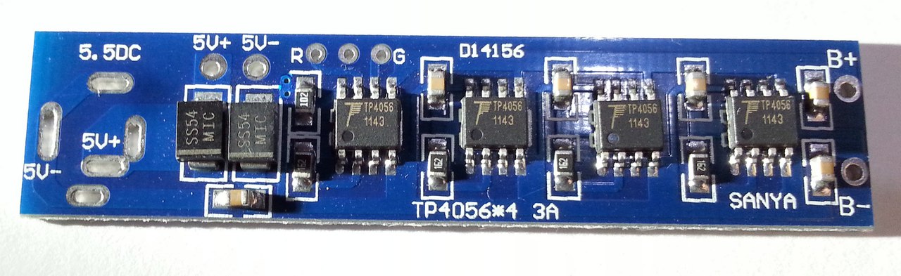
Close-up charge board:
According to the circuitry, nothing supernatural - just took and paralleled 4 controllers TP4056, at the same time reducing the maximum charging current for each controller from 1A to 750ma. At first, I could not understand why the maximum charging current is only 3A, because there are four controllers, but when I looked closer, I saw not the usual 1.2K SMD resistor, but 1.6K. And in all shoulders there is a 1.6K resistor:
Let me remind the table of the maximum charging current depending on the nominal current-current resistor:
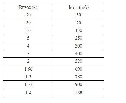
In our case, there are 1.6K resistors for each controller, 750ma per shoulder. Therefore, the total maximum charging current is 3A. It is for the better, the scarf is less heated, and 4A is already a bit too much. On the other hand, if you need a charging current 4A - change 4 resistors.
To adjust the total charging current by soldering the trimmer / variable resistor, most likely, will not work, because you need to set for each controller.
In total, it is difficult for someone who is difficult or unwilling to solder handkerchiefs - a good solution.
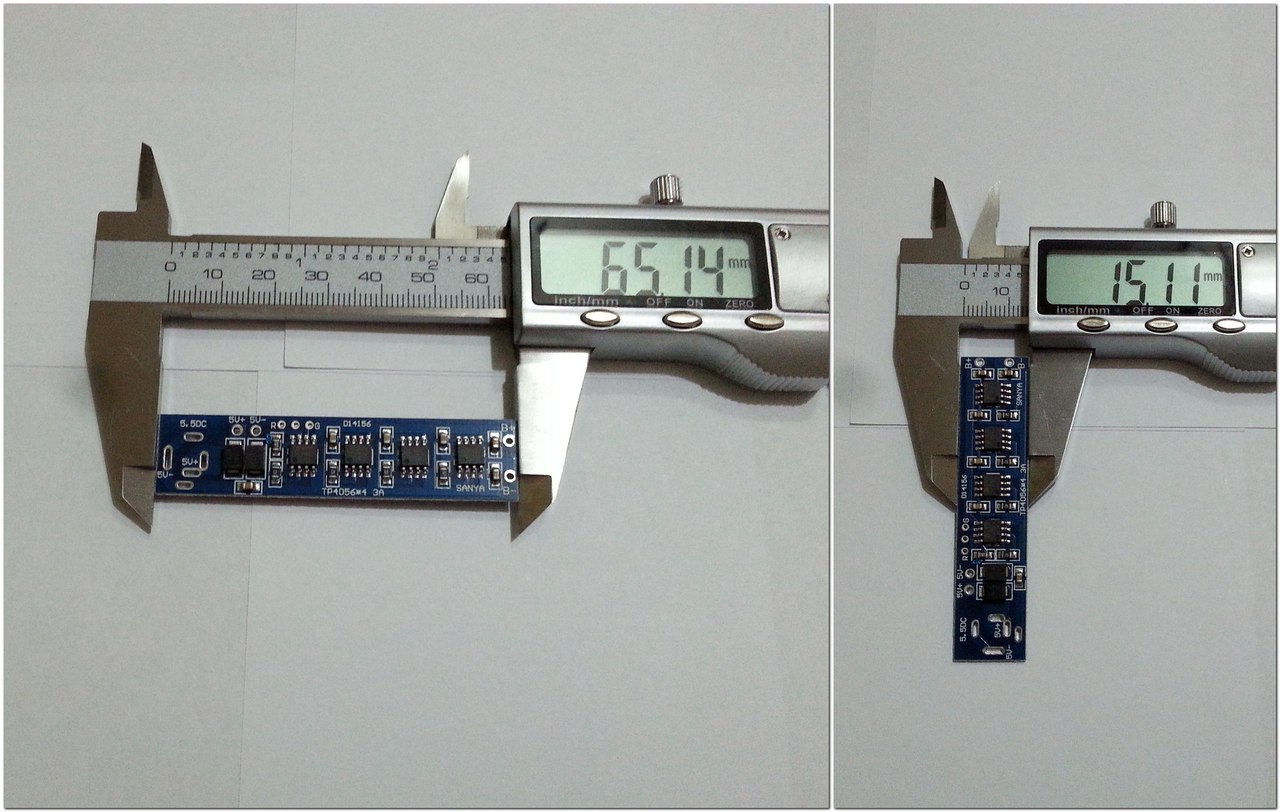
The scarf is quite small, only 65mm * 15mm:
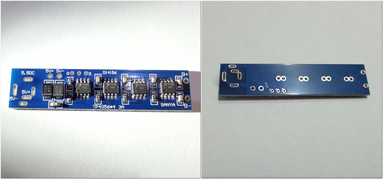
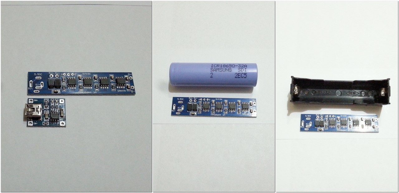
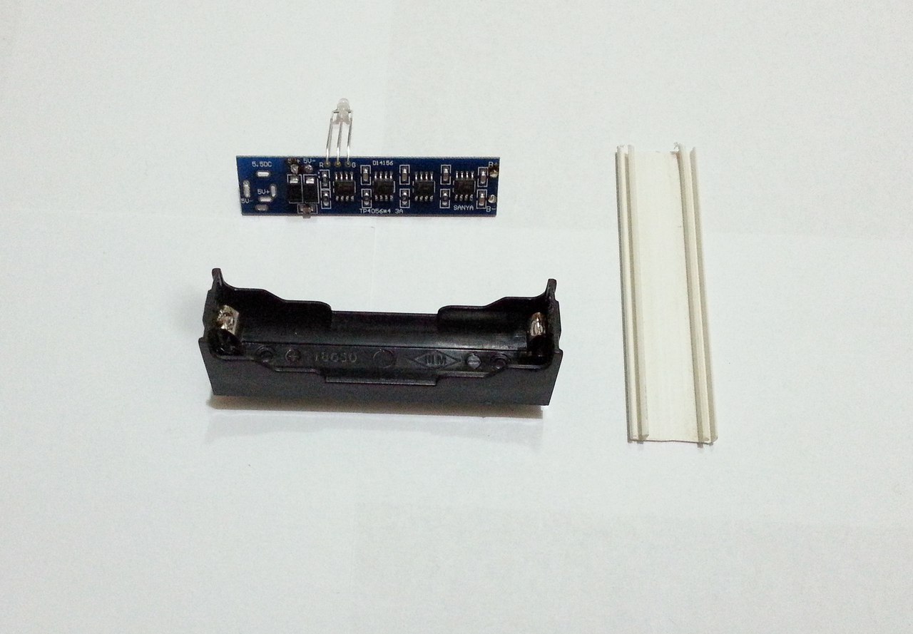
Here is a comparison with the “popular” board TP4056 on 1, 18650 battery and holder:
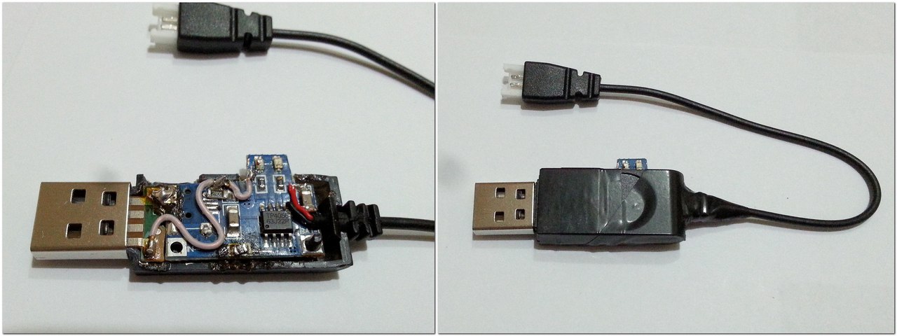
If necessary, you can bite off the front of the board, on which the DC connector is soldered and solder to the 5V + or 5V- pins, or directly to the corresponding tracks:

So the length of the scarves will be shorter by 1 centimeter. Earlier, I already reworked the folk shawl, that's what happened:
In our case, everything is easy to impossible, because the tracks on the printed circuit board do not suffer. Of course, who needs a DC connector - leave it, or we solder it through the wires to the contacts 5V + or 5V-. The microUSB and miniUSB connectors are undesirable here, they will warm up a lot, because they are not designed for such currents. And there is no need for them, because in most adapters there is a limit of 2.5A. But on the other hand, if the adapter does not turn off when overloaded, then we save on the discrete power supply, well, the current will be slightly less. Therefore, you decide ...
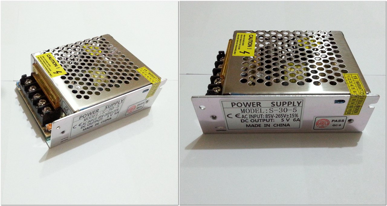
Now let's test the handkerchief. Does she really charge 3A? To do this, we will be helped by an ampervoltmeter, which often flashes in my reviews (charge current measurement) and a familiar multimeter (battery voltage measurement). As a power source - switching power supply S-30-5 at 5V / 6A:
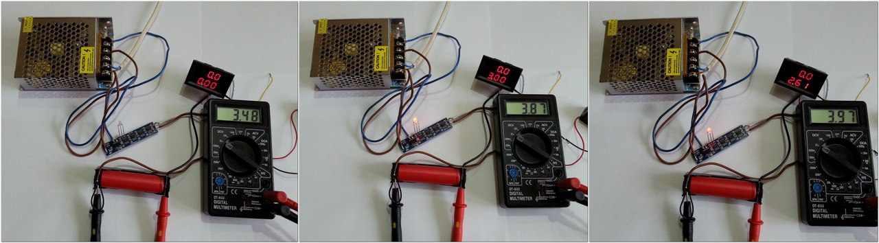
As you can see, the charge really goes with a constant current of 3A (phase CC) until the voltage on the bank exceeds 3.9V-3.95V, then it begins to gradually decrease (the CV phase begins). As soon as the bank voltage is 4.2V, the LED color changes to green, meaning that the charge is over. Although due to the inertia of the current continues to flow:
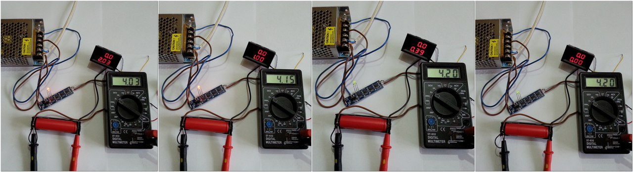
After that, another 10-15 minutes, the current decreases, while the voltage on the battery 4.21 V. As soon as the current drops to 150 mA, the controller completely cuts off the charge, the voltage on the bank drops to 4.2V.
The “squeezed out” can of Sanyo UR18650ZY 2600mah module was loaded in 75-80 minutes. Well, just great!
As an example, I will give an example of building your own charger from proven low-cost components. What we need for this:
1) Directly monitored board TP4056 * :

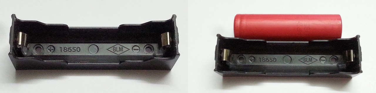
2) Holder / holder * for batteries:
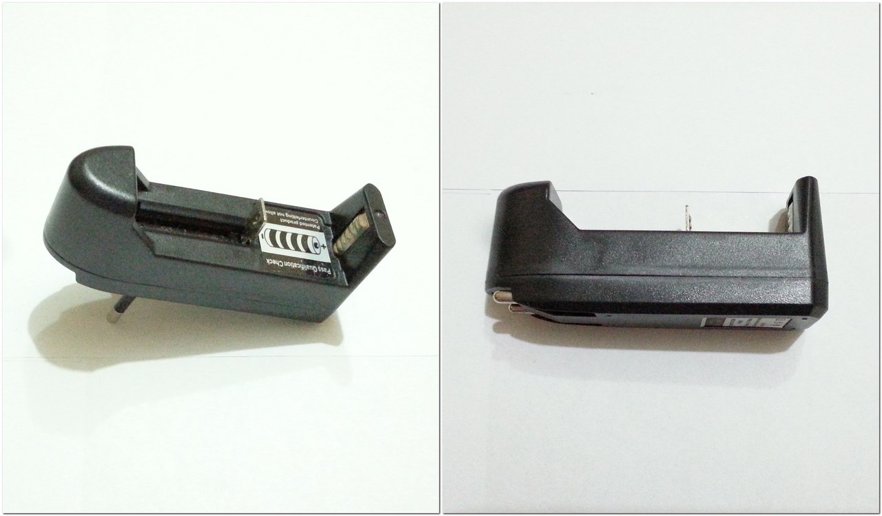
These are the holders in any case do not use, 3A for them a lot:

You can try to remake the crappy charging, dropping out all guts:
I recommend the first option, because they easily withstand 3A, because the contacts are an order of magnitude better, and they have a groove for the wire.
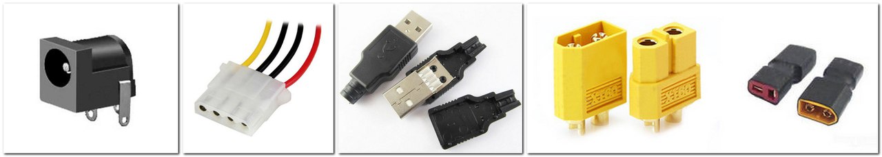
3) Any suitable connector: DC port * (comes with the card), USB (not very desirable), Molex * (when powered from a computer), power model or car connectors (which are at hand):
In a pinch, you can just pull two wires and drive the whole household on a twist, as in my case :-).
4) Quality Copper Stranded Wire * :
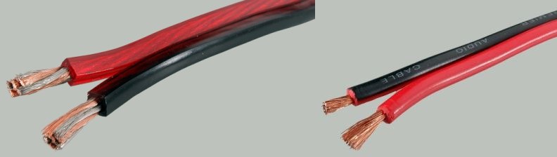
What is needed is copper, not copperplated. It is easy to determine - we clean it with a knife, and if the veins begin to shine and are not tinned, it means that the wire is copper-plated (aluminum coated with copper). I recommend either high-quality acoustic or household, such as ShVVP.
5) Power supply unit (PSU) at 5V at 5-6A (with a margin). I used the power supply S-30-5 at 5V / 6A * :
You can apply the frequently encountered power supply unit at 12V at 2-3A, which come bundled with various devices and a step-down DC-DC converter at 5A (they hold the 3A stably). But there are a couple of minuses here, because the scheme becomes more complicated and the cost of the charger rises. Therefore, if there is no suitable power supply unit available, then we use the power supply unit of the computer. The additional load of 15W is not terrible for him, unless, of course, he already does not work at the limit of his capabilities. If there is a free Molex connector available, then it will not be difficult to attach an adapter to it. In this case, we need red (+) and black (-) wires.
Since the handkerchief will be used in another device and I already have good high-current chargers, I do not need homemade charging, so the assembly, as they say, is on the knee (I will not bother the connectors):
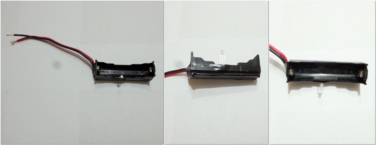
We take the holder for the battery and cut out the plastic at the ends for the wire (in the photo the lower groove):
Next, solder on the right side to the positive contact and lay the wire in the groove:
Next, we solder the negative output of the board (B-) to the other, negative output of the holder, and the wire in the slot is connected to the positive output of the board (B +):
Then solder the power wires with or without connectors, depending on which option you choose. The three-legged LED is bent at its discretion, but in order not to short its conclusions - we stretch the insulation from any wire on them:

Close the board with a plastic cover from the cable channel or a similar housing and wind it up with all known electrical tape :-). It turns out quite handicraft, but the main thing works:
Verification check, everything works:

I did not solder the connectors, but connected directly to the PSU. I recommend to solder the corresponding connector, which will withstand a long current flow 3A. At this I have everything ...
Pros:
Minuses:
Conclusion: a useful modification of the people's scarf TP4056 * on a large charging current, you can take!
That's all, with you there was a simple service for choosing sophisticated Dronk.Ru equipment. Do not forget to subscribe to our blog , there will be many more interesting things.
Speaking of Xiaomi, here we are playing 10 cool Xiaomi gadgets !
ps * - referral links marked with an asterisk, so you can save money by returning cashback up to 3%. Read more at Dronk.ru/cashback/ or you can receive up to 30% for any purchases by purchasing them through the LetyShops cashback service. Read more about who the cashback services are in our article. We select the cashback service for the 6th anniversary of Aliexpress.
Also read:

So, here is the very modification of the "folk" scarf:
Application of this board:
- Charging Li-Ion batteries built into the end device. This is often the case - there are several parallel cans in the device and 1A is too small. Well, judge for yourself, there are two or three 2.6-3 Ah banks, the total capacity is about 6-7 Ah. The charge of such a battery will take about 7-8 hours, and with this handkerchief - about 3 hours. As an example - homemade PB, cordless screwdrivers and mini-screwdrivers
- Build your "fast" charger for one or two batteries. Modern high-capacity batteries at 3300-3500mah can safely take 3-4A, and the two canned banks are all the more so (it is better to approximately equalize the potentials before charging). The manufacturers themselves allow the charge of some 3-4A cans, it is written about this in the datasheets for these banks.
TTH:
- Input connector - DC Port 5mm + duplicate pins;
- Input Voltage - 4.5V-5.5V
- The final charge voltage is 4.2V (Li-Ion batteries);
- Maximum charging current - 3A;
- Number of modules TP4056-4 (max. Acceleration current 4A);
- Indication - discrete two-color LED (red / green);
- Protection against polarity reversal - no;
- Dimensions - 65mm * 15mm.
Equipment:
- Charge charge 4 * TP4056 at 3A;
- Two-color three-legged LED (red / blue light);
- DC connector 5mm.
')
A handkerchief is delivered in the usual small package; I arrived in two or three weeks. Inside the package there was a kind of protection - two glued sheets of polyethylene foam, inside of which there was a scarf:
Close-up charge board:
According to the circuitry, nothing supernatural - just took and paralleled 4 controllers TP4056, at the same time reducing the maximum charging current for each controller from 1A to 750ma. At first, I could not understand why the maximum charging current is only 3A, because there are four controllers, but when I looked closer, I saw not the usual 1.2K SMD resistor, but 1.6K. And in all shoulders there is a 1.6K resistor:
Let me remind the table of the maximum charging current depending on the nominal current-current resistor:
In our case, there are 1.6K resistors for each controller, 750ma per shoulder. Therefore, the total maximum charging current is 3A. It is for the better, the scarf is less heated, and 4A is already a bit too much. On the other hand, if you need a charging current 4A - change 4 resistors.
To adjust the total charging current by soldering the trimmer / variable resistor, most likely, will not work, because you need to set for each controller.
In total, it is difficult for someone who is difficult or unwilling to solder handkerchiefs - a good solution.
Scarf sizes:
The scarf is quite small, only 65mm * 15mm:
Here is a comparison with the “popular” board TP4056 on 1, 18650 battery and holder:
If necessary, you can bite off the front of the board, on which the DC connector is soldered and solder to the 5V + or 5V- pins, or directly to the corresponding tracks:
So the length of the scarves will be shorter by 1 centimeter. Earlier, I already reworked the folk shawl, that's what happened:
In our case, everything is easy to impossible, because the tracks on the printed circuit board do not suffer. Of course, who needs a DC connector - leave it, or we solder it through the wires to the contacts 5V + or 5V-. The microUSB and miniUSB connectors are undesirable here, they will warm up a lot, because they are not designed for such currents. And there is no need for them, because in most adapters there is a limit of 2.5A. But on the other hand, if the adapter does not turn off when overloaded, then we save on the discrete power supply, well, the current will be slightly less. Therefore, you decide ...
Testing shawls 4 * TP4056 3A:
Now let's test the handkerchief. Does she really charge 3A? To do this, we will be helped by an ampervoltmeter, which often flashes in my reviews (charge current measurement) and a familiar multimeter (battery voltage measurement). As a power source - switching power supply S-30-5 at 5V / 6A:
As you can see, the charge really goes with a constant current of 3A (phase CC) until the voltage on the bank exceeds 3.9V-3.95V, then it begins to gradually decrease (the CV phase begins). As soon as the bank voltage is 4.2V, the LED color changes to green, meaning that the charge is over. Although due to the inertia of the current continues to flow:
After that, another 10-15 minutes, the current decreases, while the voltage on the battery 4.21 V. As soon as the current drops to 150 mA, the controller completely cuts off the charge, the voltage on the bank drops to 4.2V.
The “squeezed out” can of Sanyo UR18650ZY 2600mah module was loaded in 75-80 minutes. Well, just great!
A small example of the assembly of your charger on 3A:
As an example, I will give an example of building your own charger from proven low-cost components. What we need for this:
1) Directly monitored board TP4056 * :
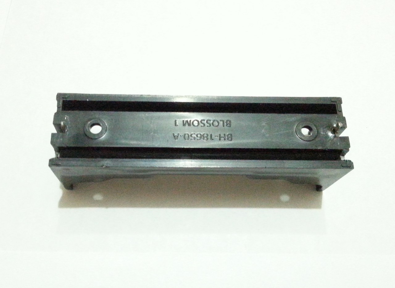
2) Holder / holder * for batteries:
These are the holders in any case do not use, 3A for them a lot:
You can try to remake the crappy charging, dropping out all guts:
I recommend the first option, because they easily withstand 3A, because the contacts are an order of magnitude better, and they have a groove for the wire.
3) Any suitable connector: DC port * (comes with the card), USB (not very desirable), Molex * (when powered from a computer), power model or car connectors (which are at hand):
In a pinch, you can just pull two wires and drive the whole household on a twist, as in my case :-).
4) Quality Copper Stranded Wire * :
What is needed is copper, not copperplated. It is easy to determine - we clean it with a knife, and if the veins begin to shine and are not tinned, it means that the wire is copper-plated (aluminum coated with copper). I recommend either high-quality acoustic or household, such as ShVVP.
5) Power supply unit (PSU) at 5V at 5-6A (with a margin). I used the power supply S-30-5 at 5V / 6A * :
You can apply the frequently encountered power supply unit at 12V at 2-3A, which come bundled with various devices and a step-down DC-DC converter at 5A (they hold the 3A stably). But there are a couple of minuses here, because the scheme becomes more complicated and the cost of the charger rises. Therefore, if there is no suitable power supply unit available, then we use the power supply unit of the computer. The additional load of 15W is not terrible for him, unless, of course, he already does not work at the limit of his capabilities. If there is a free Molex connector available, then it will not be difficult to attach an adapter to it. In this case, we need red (+) and black (-) wires.
So, with the components sorted out. Now directly build:
Since the handkerchief will be used in another device and I already have good high-current chargers, I do not need homemade charging, so the assembly, as they say, is on the knee (I will not bother the connectors):
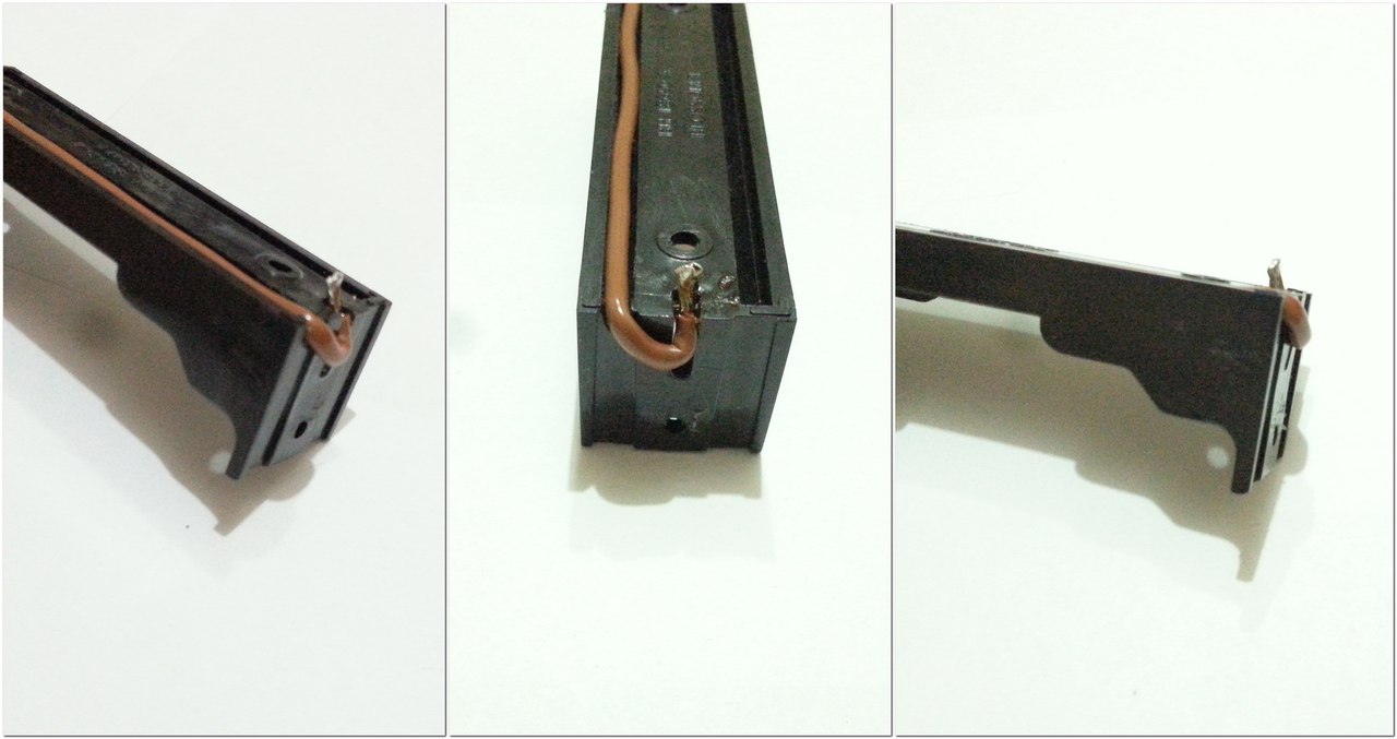
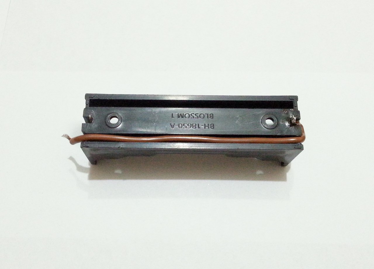
We take the holder for the battery and cut out the plastic at the ends for the wire (in the photo the lower groove):
Next, solder on the right side to the positive contact and lay the wire in the groove:
Next, we solder the negative output of the board (B-) to the other, negative output of the holder, and the wire in the slot is connected to the positive output of the board (B +):
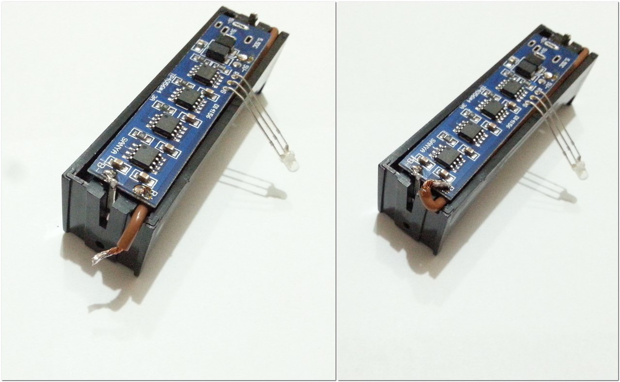
Then solder the power wires with or without connectors, depending on which option you choose. The three-legged LED is bent at its discretion, but in order not to short its conclusions - we stretch the insulation from any wire on them:
Close the board with a plastic cover from the cable channel or a similar housing and wind it up with all known electrical tape :-). It turns out quite handicraft, but the main thing works:
Verification check, everything works:
I did not solder the connectors, but connected directly to the PSU. I recommend to solder the corresponding connector, which will withstand a long current flow 3A. At this I have everything ...
Pros:
- Reliable, proven over the years element base;
- High charge current;
- The possibility of increasing the charging current to 4A by replacing the current-setting resistors;
- Small size;
- Easy installation and operation.
Minuses:
- The price is too big;
- The shawl is not designed to charge consecutive assemblies (2S, 3S, 4S and more can not);
- External power required;
- Afraid of reversal;
- Some inhibition of the last phase of the charge (CV).
Conclusion: a useful modification of the people's scarf TP4056 * on a large charging current, you can take!
That's all, with you there was a simple service for choosing sophisticated Dronk.Ru equipment. Do not forget to subscribe to our blog , there will be many more interesting things.
Speaking of Xiaomi, here we are playing 10 cool Xiaomi gadgets !
ps * - referral links marked with an asterisk, so you can save money by returning cashback up to 3%. Read more at Dronk.ru/cashback/ or you can receive up to 30% for any purchases by purchasing them through the LetyShops cashback service. Read more about who the cashback services are in our article. We select the cashback service for the 6th anniversary of Aliexpress.
Also read:
- Carnival discounts for fans of Xiaomi
- Smart watch or smart bracelet? Weigh the pros and cons of the example of Xiaomi and LG
- Lively Chinese smartphones. Part 1
- Lively Chinese smartphones. Part 2
- 5 home projectors
- Chinese tablets with Dual OS, for those who can not make a choice
- 10 gadgets for geeks with Gearbest at a discount in honor of the birthday of the site
- Chuwi history - from MP3 players in 2004 to tablets on Windows 10 in 2016
Source: https://habr.com/ru/post/392825/
All Articles