"Digital Lab" NR05: make a combination lock
We continue the series of articles on using the capabilities of the Digital Lab NR05 for studying the programming of microcontrollers using the example of Arduino and the design of useful electronic devices.
Our material does not pretend to a complete design, but, as you will see, it fully performs all the basic functions of a combination lock, and can serve as a good illustration of the capabilities of microcontrollers and the use of external plug-ins. The program for the microcontroller can be altered at your discretion, adding or changing the functions of the lock, and increasing the level of your knowledge in programming.
')
We will use, first of all, the fact that the expansion board, which is part of the set, has a two-line LCD display, as well as 5 buttons. We use these elements to build a code lock.
Let us set the following requirements:
1. There are 5 buttons to enter the code that opens the lock;
2. The leftmost button corresponds to code 1, then from left to right - 2,3,4,5;
3. The number of digits of the entered code can be any (within reasonable limits) and simply installed in the program;
4. The dialed code is displayed as asterisks;
5. If the entered code coincides with the model code, a positive impulse of the duration specified in the program is given to the actuator;
6. In the event of an erroneous code entry, an error message appears;
7. If the code is partially typed, after some time the typed values are reset.
8. We use the display, RGB-LED and emitter included in the set to display information that is understandable to the user.
9. We will open a real electromechanical lock, powered by 12 volts.
Now we will select the device that will supply the opening voltage to the lock. This voltage in accordance with the passport of the electromechanical lock, which we will open, is 12 volts at a current of about 1 ampere. The NR05 expansion board cannot work with such voltages and currents, therefore an additional switching module is needed. Such modules can be MP515 relays offered by Master Kit, or MP2211 , MP4411 relay units , depending on whether we want to control not only the lock, but also other devices, for example, turn on the light when opening the door. All of these devices are compatible with Arduino control signal levels. In our particular case, we use the MP2211 module with two relays.
Considering the above, let's draw a wiring diagram of the devices used:
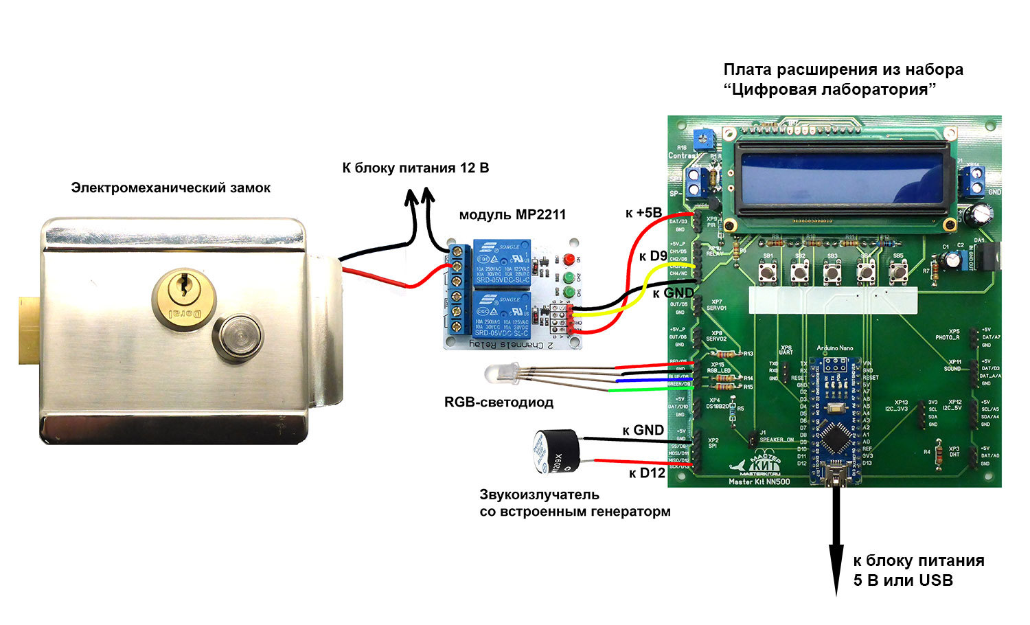
If you look closely at the marking of the expansion card, we will see that the green channel of the RGB LED GREEN and the output to the CH3 relay are connected to the same D9 Arduino Nano pin. In this case, this is permissible, since the input of the control circuit of the relay has a rather high input resistance, and the output D9 is used only as a digital output. In the general case, you should check whether the conclusions of the board you are using are not connected to the same Arduino output, and avoid such a situation.
The lock consumes a fairly large current during operation, so we power it and the control circuit separately.
The listing of the sketch is provided with detailed comments that will help you understand the program.
Nevertheless, we draw your attention to some of its features.
As we have already written, in the expansion card a button connection scheme is applied, using only one Arduino output. This scheme saves microprocessor pins, but does not allow to process simultaneous pressing of several buttons simultaneously, but in our case it is not necessary. Notice the get_key function at the end of the sketch. If no button is pressed, the function returns 0; if pressed, the number of the button pressed.
Also look at the implementation of the comparison of two arrays: reference and dialed codes:
int compareResult = 1;
for (int i = 0; i <codeLength; i ++)
if (codeOrigin [i]! = codePressed [i])
compareResult = 0; // if at least one pair of elements is not equal
The question of the algorithm for such a comparison is quite often discussed in programming forums, but each time it comes down to element-by-element comparison, which is used in our case. The variable compareResult remains equal to 1 if the elements of arrays with identical indices are equal, and becomes equal to 0 if at least one pair of elements does not match.
For displaying Cyrillic characters, the LiquidCrystalRus library, developed by Ilya Danilov, is used. For the library to work correctly, three lines must be present in the header of our sketch:
#include <LiquidCrystalRus.h>
#include <LineDriver.h>
#include <LiquidCrystalExt.h>
And the initialization of the display should look like this:
LiquidCrystalRus lcd (A1, A2, A3, 2, 4, 7);
The length of the entered code is given by a predefined codeLength constant, for example, for a code of six taps
#define codeLength 6
The array of reference values for a code with a length of 6 clicks is given by the following line:
const int codeOrigin [codeLength] = {1, 2, 3, 4, 5, 3};
The number of values in curly brackets must be equal to codeLength. If there are more values, the compiler will give an error, if less, there will be no error, but random values will be used as missing elements, which will not give an opportunity to type the code that will open the lock.
Every 5 seconds, the program resets dialed code elements. If the button was pressed, the pressing time is remembered, and the countdown of the five-second interval begins again. This is implemented with the millis () built-in functions, which returns the number of milliseconds elapsed since the start of the sketch, and the variables oldTime and currentTime.
We give a short video showing the operation of the code lock:
For the curious and inquisitive electronic programmers, you can throw a few more ideas for self-completion of the sketch and the inclusion in the scheme of modules that expand the capabilities of the castle. For example, enter a master code into the program, with the help of which the lock is transferred to the programming mode and remembers the pressed buttons as a reference code, in order not to change this code in the sketch. Programming a new code ends if the interval between clicks exceeds a certain time.
Or, based on the material devoted to the interaction of Arduino with a smartphone via Bluetooth, make a lock that opens with the code sent by this smartphone itself.
You can also simply enter into our device a wireless control channel. To do this, it is enough to use two modules: the MP910 transmitter and one-channel receiver with a relay output MP911 , operating at a frequency of 433 MHz. The relay contacts of the MP2211 module are connected in parallel with the remote control button, and the relay of the receiver module is connected to the lock. The control distance can be up to 100 m.
Study Arduino, study microcontrollers and their programming - and you can create a lot of smart and useful electronic devices!
Our material does not pretend to a complete design, but, as you will see, it fully performs all the basic functions of a combination lock, and can serve as a good illustration of the capabilities of microcontrollers and the use of external plug-ins. The program for the microcontroller can be altered at your discretion, adding or changing the functions of the lock, and increasing the level of your knowledge in programming.
')
We will use, first of all, the fact that the expansion board, which is part of the set, has a two-line LCD display, as well as 5 buttons. We use these elements to build a code lock.
Let us set the following requirements:
1. There are 5 buttons to enter the code that opens the lock;
2. The leftmost button corresponds to code 1, then from left to right - 2,3,4,5;
3. The number of digits of the entered code can be any (within reasonable limits) and simply installed in the program;
4. The dialed code is displayed as asterisks;
5. If the entered code coincides with the model code, a positive impulse of the duration specified in the program is given to the actuator;
6. In the event of an erroneous code entry, an error message appears;
7. If the code is partially typed, after some time the typed values are reset.
8. We use the display, RGB-LED and emitter included in the set to display information that is understandable to the user.
9. We will open a real electromechanical lock, powered by 12 volts.
Now we will select the device that will supply the opening voltage to the lock. This voltage in accordance with the passport of the electromechanical lock, which we will open, is 12 volts at a current of about 1 ampere. The NR05 expansion board cannot work with such voltages and currents, therefore an additional switching module is needed. Such modules can be MP515 relays offered by Master Kit, or MP2211 , MP4411 relay units , depending on whether we want to control not only the lock, but also other devices, for example, turn on the light when opening the door. All of these devices are compatible with Arduino control signal levels. In our particular case, we use the MP2211 module with two relays.
Considering the above, let's draw a wiring diagram of the devices used:
If you look closely at the marking of the expansion card, we will see that the green channel of the RGB LED GREEN and the output to the CH3 relay are connected to the same D9 Arduino Nano pin. In this case, this is permissible, since the input of the control circuit of the relay has a rather high input resistance, and the output D9 is used only as a digital output. In the general case, you should check whether the conclusions of the board you are using are not connected to the same Arduino output, and avoid such a situation.
The lock consumes a fairly large current during operation, so we power it and the control circuit separately.
Here is a sketch, working in Arduino, spoiler
// Code lock on the five buttons with the display on the LCD and RGB-LED
// based on the expansion card from the set NR05
// ------------------------------------------------ -------------------
// we connect the libraries LiquidCrystalRus
#include <LiquidCrystalRus.h>
#include <LineDriver.h>
#include <LiquidCrystalExt.h>
// determine the pins for the RGB LED and sound emitter
#define red 5
#define blue 6
#define green 9
#define beep 12
// determine how many buttons we have connected
#define NUM_KEYS 5
// for each button enter calibration values (derived experimentally)
int adcKeyVal [NUM_KEYS] = {30, 150, 360, 535, 760};
////////////////////////////////////////////////// /////////
// length of the code that opens the lock
#define codeLength 6
// array containing the code that opens the lock. The number of array elements must be equal to codeLength
const int codeOrigin [codeLength] = {1, 2, 3, 4, 5, 3};
// lock unlock time, milliseconds
const int unlockTime = 400;
////////////////////////////////////////////////// /////////
// array to record the number of keys pressed
int codePressed [codeLength];
// push counter (the lock is unlocked by the fifth push)
int pressCount;
// variables for the code dialing inactivity counter
unsigned long oldTime;
unsigned long currentTime;
const int timeout = 5; // timeout time when typing code, sec. After a timeout, the incomplete dialed code is reset.
// ------------------------------------------------ -----------------------
// initialize the display, explaining to the program where the RS, EN, DB4, DB5, DB6, DB7 lines are connected
LiquidCrystalRus lcd (A1, A2, A3, 2, 4, 7);
// ------------------------------------------------ -----------------------
// This function will be executed 1 time at the time of launching the Arduino program
void setup ()
{
// initialize the LCD: 16 characters and 2 lines
lcd.begin (16, 2);
// the cursor is on the first line (top) and the first left character
// write on the display "Master Kit"
lcd.print ("Master Kit");
// set the cursor to the first position in the second line
lcd.setCursor (0,1);
lcd.print ("totcr .:");
lcd.print (unlockTime);
lcd.print (“ms”);
// pause for 2000 milliseconds = 2 seconds
delay (2000);
// clear the display
lcd.clear ();
// reset the click counter
pressCount = 0;
// set the mode "on output" for connecting the RGB-LED and sound emitter
pinMode (red, OUTPUT);
pinMode (blue, OUTPUT);
pinMode (green, OUTPUT);
pinMode (beep, OUTPUT);
}
// ------------------------------------------------ -----------------------
// This function will be executed after the setup function and will repeat an infinite number of times after it has finished.
void loop () {
// write the current time (in milliseconds) elapsed since the program began to run
currentTime = millis ();
// check if the timeout for entering the code has not reached
if (currentTime - oldTime <= timeout * 1000) {
// start a variable named key
int key;
// write to this variable number of the pressed button, invoking the get_key function described below
key = get_key ();
lcd.setCursor (0, 0);
lcd.print ("Enter the code:");
// turn on the blue LED
digitalWrite (blue, HIGH);
if (key> 0) {// if the button is pressed
codePressed [pressCount] = key; // write the number of the pressed button to the array
// short signal of the emitter (50 ms)
digitalWrite (beep, HIGH);
delay (50);
digitalWrite (beep, LOW);
// typing on the second line of the asterisk, flashing blue LED
lcd.setCursor (pressCount, 1);
lcd.print ('*');
digitalWrite (blue, LOW);
delay (200);
digitalWrite (blue, HIGH);
pressCount ++; // increment the hit count
// reset the timeout timer
oldTime = currentTime;
}
}
// if the timeout is reached, reset the partially dialed code
else {
pressCount = 0;
lcd.clear ();
oldTime = currentTime;
}
// if all code is entered, compare two arrays element by element: codeOrigin and codePressed
if (pressCount == codeLength) {
int compareResult = 1;
for (int i = 0; i <codeLength; i ++)
if (codeOrigin [i]! = codePressed [i])
compareResult = 0; // if at least one pair of elements is not equal
// if the correct code is entered
if (compareResult == 1) {// if arrays match
digitalWrite (blue, LOW);
digitalWrite (green, HIGH);
lcd.setCursor (0, 0);
lcd.print ("Open");
delay (unlockTime);
digitalWrite (green, LOW);
pressCount = 0;
delay (1000);
lcd.clear ();
digitalWrite (blue, HIGH);
}
// if wrong code is entered
else {
lcd.setCursor (0, 1);
lcd.print (“Invalid code");
digitalWrite (blue, LOW);
digitalWrite (red, HIGH);
digitalWrite (beep, HIGH);
delay (2000);
pressCount = 0;
lcd.clear ();
digitalWrite (beep, LOW);
digitalWrite (blue, HIGH);
digitalWrite (red, LOW);
}
}
}
// ------------------------------------------------ -----------------------
// This function will be executed only when it was called from the program.
// The function reads the value from the ADC, where the analog keyboard is connected
// and compares with the calibration values, identifying the number of the pressed button
int get_key ()
{
int input = analogRead (A6);
int k;
for (k = 0; k <NUM_KEYS; k ++)
if (input <adcKeyVal [k])
return k + 1;
return 0;
}
// end of the sketch
The listing of the sketch is provided with detailed comments that will help you understand the program.
Nevertheless, we draw your attention to some of its features.
As we have already written, in the expansion card a button connection scheme is applied, using only one Arduino output. This scheme saves microprocessor pins, but does not allow to process simultaneous pressing of several buttons simultaneously, but in our case it is not necessary. Notice the get_key function at the end of the sketch. If no button is pressed, the function returns 0; if pressed, the number of the button pressed.
Also look at the implementation of the comparison of two arrays: reference and dialed codes:
int compareResult = 1;
for (int i = 0; i <codeLength; i ++)
if (codeOrigin [i]! = codePressed [i])
compareResult = 0; // if at least one pair of elements is not equal
The question of the algorithm for such a comparison is quite often discussed in programming forums, but each time it comes down to element-by-element comparison, which is used in our case. The variable compareResult remains equal to 1 if the elements of arrays with identical indices are equal, and becomes equal to 0 if at least one pair of elements does not match.
For displaying Cyrillic characters, the LiquidCrystalRus library, developed by Ilya Danilov, is used. For the library to work correctly, three lines must be present in the header of our sketch:
#include <LiquidCrystalRus.h>
#include <LineDriver.h>
#include <LiquidCrystalExt.h>
And the initialization of the display should look like this:
LiquidCrystalRus lcd (A1, A2, A3, 2, 4, 7);
The length of the entered code is given by a predefined codeLength constant, for example, for a code of six taps
#define codeLength 6
The array of reference values for a code with a length of 6 clicks is given by the following line:
const int codeOrigin [codeLength] = {1, 2, 3, 4, 5, 3};
The number of values in curly brackets must be equal to codeLength. If there are more values, the compiler will give an error, if less, there will be no error, but random values will be used as missing elements, which will not give an opportunity to type the code that will open the lock.
Every 5 seconds, the program resets dialed code elements. If the button was pressed, the pressing time is remembered, and the countdown of the five-second interval begins again. This is implemented with the millis () built-in functions, which returns the number of milliseconds elapsed since the start of the sketch, and the variables oldTime and currentTime.
We give a short video showing the operation of the code lock:
For the curious and inquisitive electronic programmers, you can throw a few more ideas for self-completion of the sketch and the inclusion in the scheme of modules that expand the capabilities of the castle. For example, enter a master code into the program, with the help of which the lock is transferred to the programming mode and remembers the pressed buttons as a reference code, in order not to change this code in the sketch. Programming a new code ends if the interval between clicks exceeds a certain time.
Or, based on the material devoted to the interaction of Arduino with a smartphone via Bluetooth, make a lock that opens with the code sent by this smartphone itself.
You can also simply enter into our device a wireless control channel. To do this, it is enough to use two modules: the MP910 transmitter and one-channel receiver with a relay output MP911 , operating at a frequency of 433 MHz. The relay contacts of the MP2211 module are connected in parallel with the remote control button, and the relay of the receiver module is connected to the lock. The control distance can be up to 100 m.
Study Arduino, study microcontrollers and their programming - and you can create a lot of smart and useful electronic devices!
Source: https://habr.com/ru/post/392559/
All Articles