Integrated solution for capturing and retaining returnable spacecraft stages
This publication is designed for those who, watching the progress of SpaceX in the area of returning accelerating stages, decided not to lag behind, move in the same direction, but have not yet managed to invest in 2 tons of landing legs.
The possibility of re-use of the upper stages of spacecraft can significantly reduce the cost of their launches. At the same time, it is desirable to minimize the costs and associated changes in their design, since the main function of the stage is still the output of the payload into space. The proposed solution was the result of a search in the specified direction.
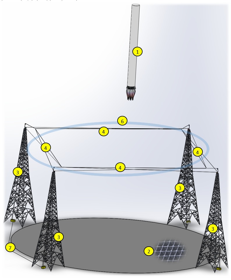
The complex is a landing site (2), based on the ground or on a barge, with dimensions sufficient for guaranteed reception, taking into account the accuracy of the landing of the returned steps. The landing area is designed to withstand the weight of the return stage (1) and, at the base, has a cellular structure (2) that allows reactive gases through. Directly under the landing area is the system of removal and quenching of reactive gases during deceleration steps, in the simplest case, it may be a pool with water. Along the perimeter are four high-rise supports (3). At the required height and on the same level, retaining straps (4) come out of each support, forming four loops, which form one level of the gripping loop (6). When using a multi-level (5) locking loop, it becomes possible to fully hold the step (1) in the resulting multi-level network. In this case, the need for a landing site (2) disappears altogether.
')
In general, the design looks and functions as follows:
At the initial moment on the site, ready to receive steps, the locking loop (6) is as wide open as possible, forming the perimeter of the locking area.
From the moment when the landing point of the stage becomes fairly accurately known, the second stage begins: positioning and forming a locking loop (6) around the descending stage (1).

The automated system, tracking the position of the loop (6) around the step (1), with the help of winches (7) quickly narrows the grip loop (6), without touching the surface of the step until it is fully seated. But, if necessary, the loop (6) can be actively involved during the landing to stabilize the position of the step, limiting the possibility of deviations.
At the moment of steady contact with the step (1) of the landing pad, the loop (6) is tightened. This ensures reliable fixation of the stage (1) in a vertical position. The location of the loop at the top allows you to securely hold the steps in a vertical position with light effort.

Above was considered the option of landing on the platform. In this case, the loop is only able to support step (1) in a vertical position, but with an increase in the number of levels in the loop, it becomes possible to completely capture and hold the return step on weight in the network formed by the loop.

An example of a three-level locking loop in the sea-based variant, on a barge (8). Full retention of the step (1) in the loop makes it possible to abandon the design of the landing pad.

The main advantages of this solution.
The possibility of re-use of the upper stages of spacecraft can significantly reduce the cost of their launches. At the same time, it is desirable to minimize the costs and associated changes in their design, since the main function of the stage is still the output of the payload into space. The proposed solution was the result of a search in the specified direction.
The complex is a landing site (2), based on the ground or on a barge, with dimensions sufficient for guaranteed reception, taking into account the accuracy of the landing of the returned steps. The landing area is designed to withstand the weight of the return stage (1) and, at the base, has a cellular structure (2) that allows reactive gases through. Directly under the landing area is the system of removal and quenching of reactive gases during deceleration steps, in the simplest case, it may be a pool with water. Along the perimeter are four high-rise supports (3). At the required height and on the same level, retaining straps (4) come out of each support, forming four loops, which form one level of the gripping loop (6). When using a multi-level (5) locking loop, it becomes possible to fully hold the step (1) in the resulting multi-level network. In this case, the need for a landing site (2) disappears altogether.
')
In general, the design looks and functions as follows:
At the initial moment on the site, ready to receive steps, the locking loop (6) is as wide open as possible, forming the perimeter of the locking area.
From the moment when the landing point of the stage becomes fairly accurately known, the second stage begins: positioning and forming a locking loop (6) around the descending stage (1).
The automated system, tracking the position of the loop (6) around the step (1), with the help of winches (7) quickly narrows the grip loop (6), without touching the surface of the step until it is fully seated. But, if necessary, the loop (6) can be actively involved during the landing to stabilize the position of the step, limiting the possibility of deviations.
At the moment of steady contact with the step (1) of the landing pad, the loop (6) is tightened. This ensures reliable fixation of the stage (1) in a vertical position. The location of the loop at the top allows you to securely hold the steps in a vertical position with light effort.
Above was considered the option of landing on the platform. In this case, the loop is only able to support step (1) in a vertical position, but with an increase in the number of levels in the loop, it becomes possible to completely capture and hold the return step on weight in the network formed by the loop.
An example of a three-level locking loop in the sea-based variant, on a barge (8). Full retention of the step (1) in the loop makes it possible to abandon the design of the landing pad.
The main advantages of this solution.
- All the complexities and design changes associated with solving the problem of landing the return stage are transferred from the return stage to the landing site. As a result, this minimizes changes in the design of the stage while maintaining its previous weight and reliability.
- The cable system allows you to securely fix the stage at any point on the landing area of a sufficiently large area.
- The loopback contact form allows you to avoid point loads and distribute the force holding the stage around the circumference, along the contact point of the loop with the body at the height of the stage, using a multi-level scheme.
- The absence of load in the rope system at the moment of loop positioning around the step body allows: to quickly and accurately perform positioning, which is especially important in unpredictably changing weather conditions — strong gusty wind, rolling barges, during sea basing; use high-speed winches rather simple design.
When operating in the sea-based, the barge eliminates the need for additional means of fixation. The joint and well-coordinated work of the positioning system on board the return stage and the control system of the landing loop grip will significantly increase the reliability of the stage retention even in the most difficult conditions.
The modern level of development of reactive technology does not allow changing the thrust of a jet engine dynamically and in a wide range. This is not necessary when taking off, but to ensure a “soft” landing, this ability becomes a crucial factor.
When landing, especially in its latest phase, the main way to stabilize the vertical position of the stage is to change the thrust vector of the brake motors. Therefore, before a full landing, it is desirable to have a strong enough thrust. If the landing pad is a continuous flat surface, then at small (few meters) heights, due to the “Ground effect”, the vertical component of thrust (the efficiency of reactive gases when braking) increases significantly as the level to the surface decreases. landing pad. At the same time, the efficiency of transverse correction by changing the thrust vector does not increase so much, but its characteristics change greatly.
To compensate for the effects of the “Screen Effect”, it is necessary to greatly reduce the thrust, at the same time it significantly impairs the possibility of lateral stabilization.
Reducing the thrust is possible in a fairly narrow range and to a certain, minimum level below which the engine shuts off, and, accordingly, its thrust from the minimum level drops sharply to zero.
To expand the range of variation of the magnitude of the thrust, it is necessary to use a structure consisting of several engines. When the engines achieve the minimum permissible thrust, this allows for its further reduction for the stage as a whole, by turning them off one by one.
Minimizing the “Screen Effect” will increase the controllability of the stage at the most recent critical landing points.
The proposed solution is either to use the landing pad, the base of which has a cellular structure, or to completely abandon the landing pad by capturing and holding the rocket in the proposed multi-level network. It is obvious that the landing site, in turn, must be located at a sufficient height, in order to avoid the negative impact of the land under it. To reduce this height, a pool with water can be positioned under the platform, which, when in contact with reactive gases, will effectively cool them, reducing their volume, and thus even more suppressing the manifestation of the “Ground effect”.
In the article I omitted some implementation details. Unirail.org - the source, those who want to know them.
How destructive the load on the body of the rocket during the capture and retention:.
On the example of Falcon 9 (the normal position of the rocket after the return)
Such a significant load on the body, as in such a horizontal position, in the proposed capture system is unattainable, and this, please note, is the normal position after return.
Source: https://habr.com/ru/post/392071/
All Articles