FLProg + nooLite (continued)
In a previous post, I talked about the implementation of nooLite hardware support in the FLProg program. My omission was not to tell about one very convenient function of this equipment, which allows you to connect several transceivers to one UART port and handle them independently. I decided to correct this omission.
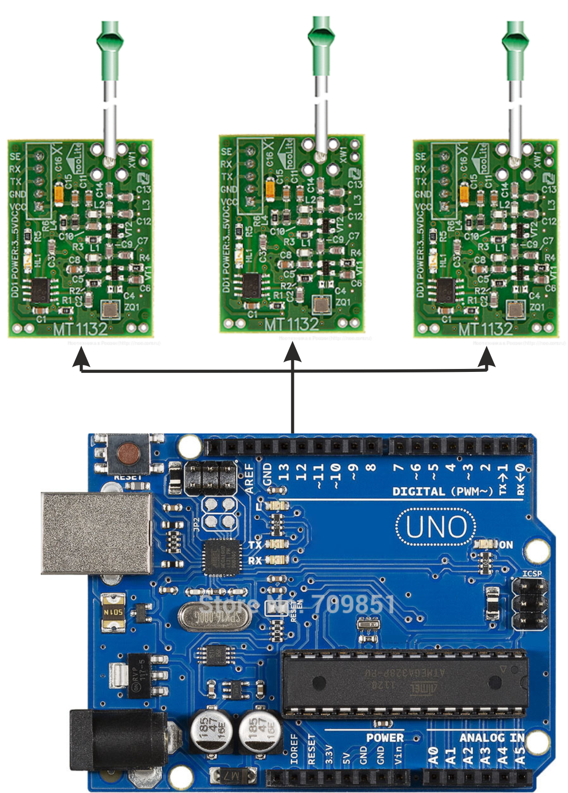
The scheme of connecting several transceivers to one UART port (taken from the documentation on the transceiver) looks like this:

')
A feature of this inclusion is to use the inputs of SE transceivers. If 0 V is fed to this input, the transceiver will not respond to commands transmitted via the UART, and if 3-5V is sent, then the commands will be executed.
In this lesson we will turn on and off several loads using different transceivers.
The scheme of the test stand:

Create a new project, and configure the input - output controller in it.
First we create three inputs for the buttons:
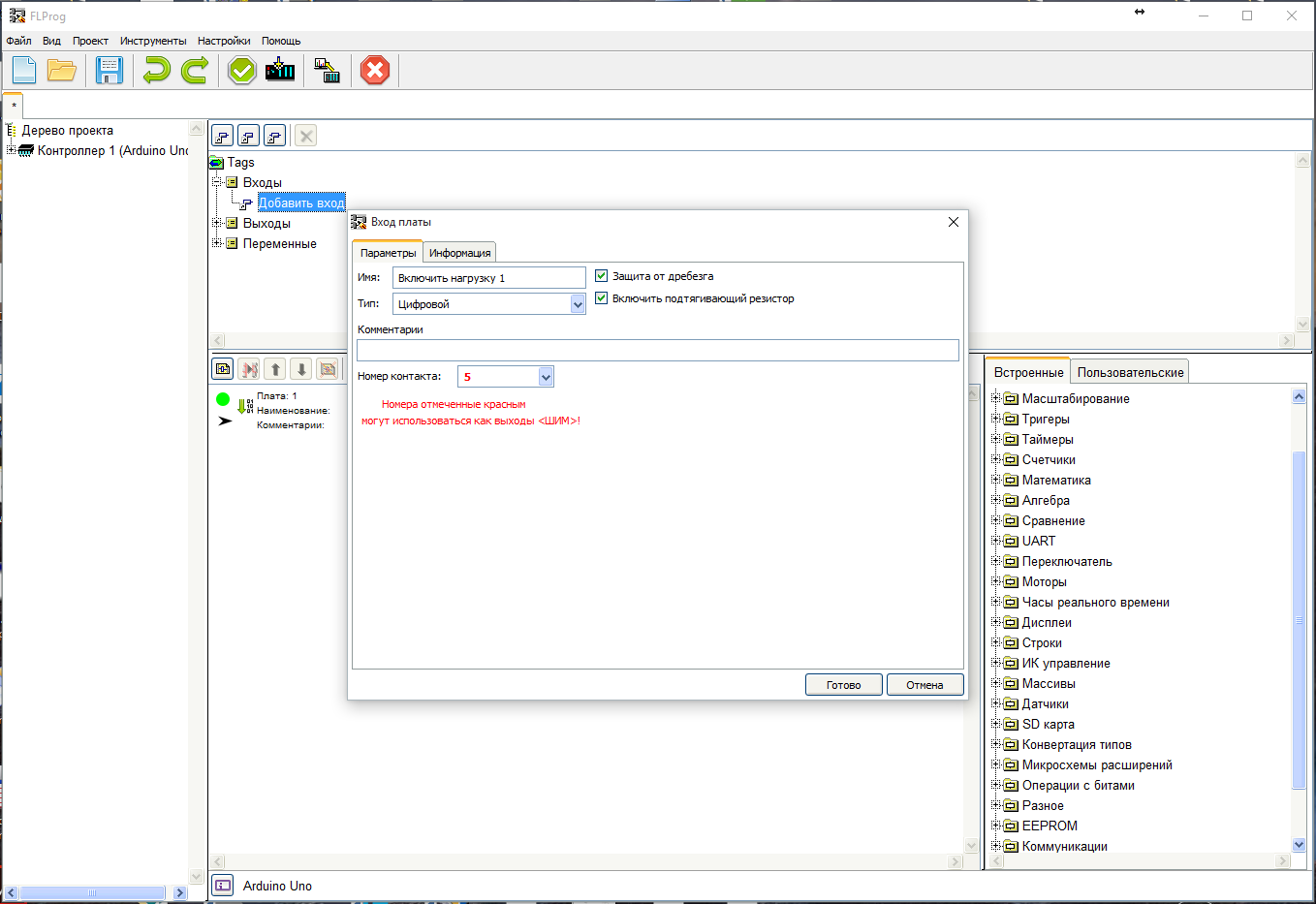
Since our buttons are connected between GND and the input, we turn on the pull-up resistors, and for accurate operation, we include bounce protection.

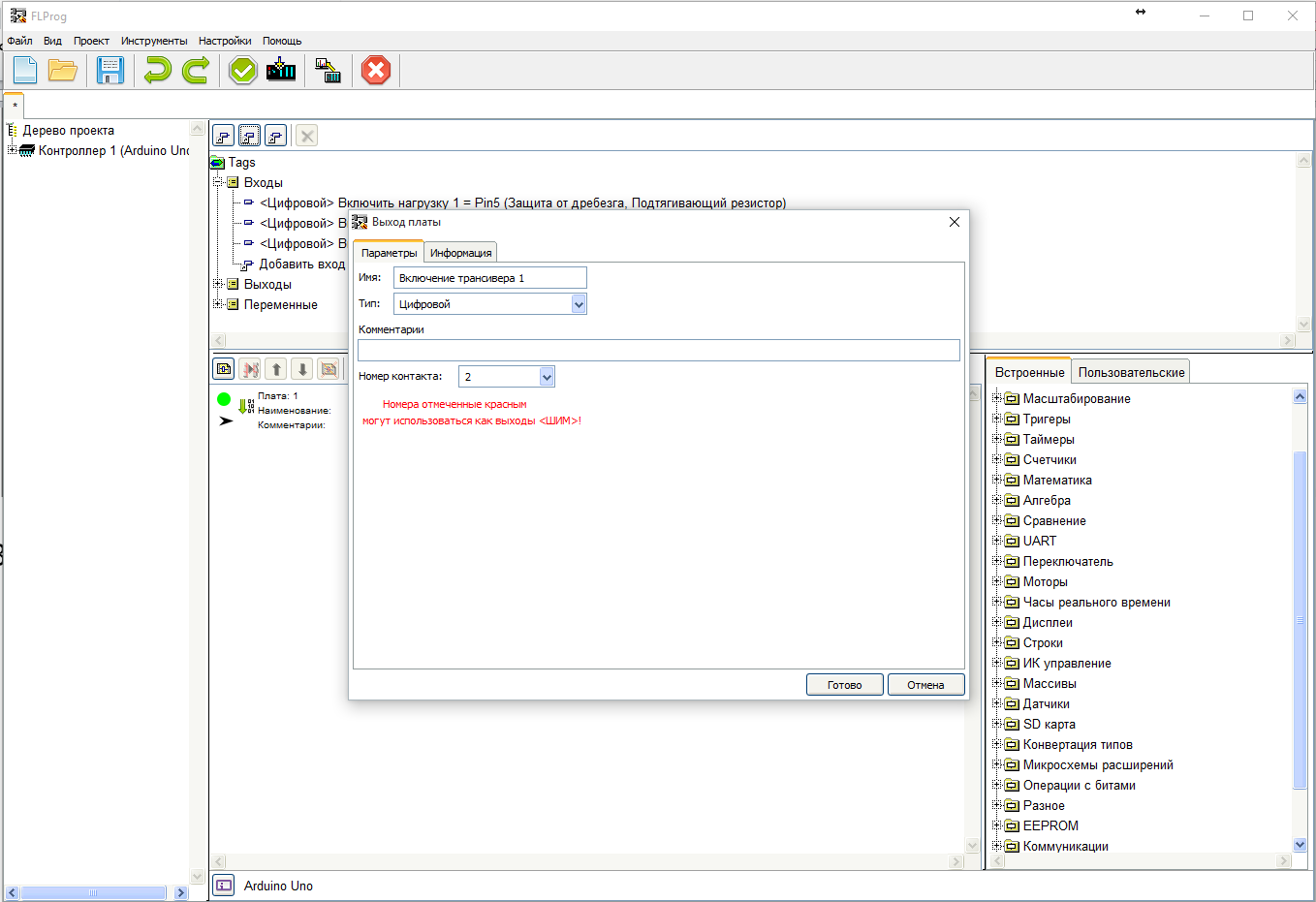
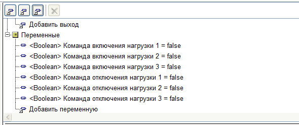
Then we create three outputs for controlling transceivers.

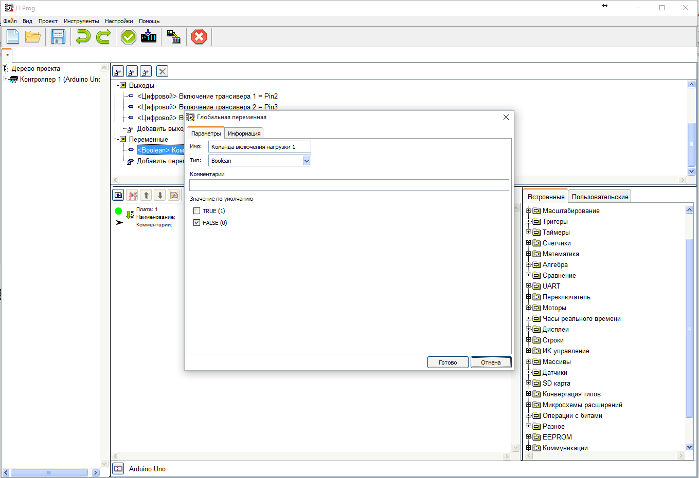
Then create six variables for control commands.
Now we drag the first input to the scheme, two R-trigger blocks (Block Library - Triggers folder), as well as two variables - “Command to turn on load 1” and “Command to turn off load 1”. Then we connect them in accordance with the scheme:
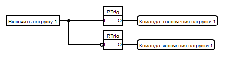
How does she work? Since we have a button turned on between GND and an input, as well as a pull-up resistor is included, when the button is released, the output of the input block will be 1, and when the button is pressed, 0. The upper R-Triger selects the leading edge (going from 0 to 1) there is a moment of releasing the button and creates in the variable “Command to disconnect load 1” a short impulse to disconnect the load. The lower R-Trigger, since its input is inverted, produces a trailing edge (going from 1 to 0) - that is, the moment the button is pressed. And it also forms at this moment a short impulse in the variable “Command to turn on load 1”.
Now we repeat this scheme for the remaining inputs.

Let's call this board "Allocation of Fronts" and create another one. Immediately you can call it - "Transceiver Management". Drag and drop the variables “Command to turn on the load 1” and “Command to turn off the load 1”, the OR block (Element library - the folder “Basic elements”) and the output “Turn on the transceiver 1” onto it. Then we connect them in accordance with the scheme:
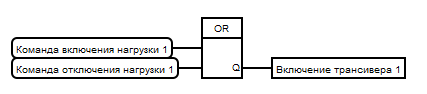
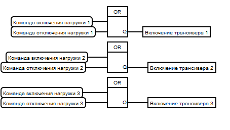
How does she work? If there is 1 in the variable “Command to turn on the load 1” OR in the variable “Command to disconnect the load 1”, the output “Turn on transceiver 1” appears in the log 1 (THEN the transceiver 1 will work out commands sent to it). Repeat this scheme for other transceivers.
Let's create a new “Sending Commands” board.
For the operation of this scheme, it is important that the control of the transceivers be located, and the sending of commands is on different boards, and the control board is located higher than the sending of commands. This ensures that the transceiver first turns on, and then the command goes to it. The order of execution of commands within the same board is not so straightforward and subject to a more complex algorithm.
Drag and drop all of the enable command variables to the lower board, the OR block (Element library — Basic Elements folder), and the nooLite transceiver control unit (Element library — Miscellaneous folder). Connect them.

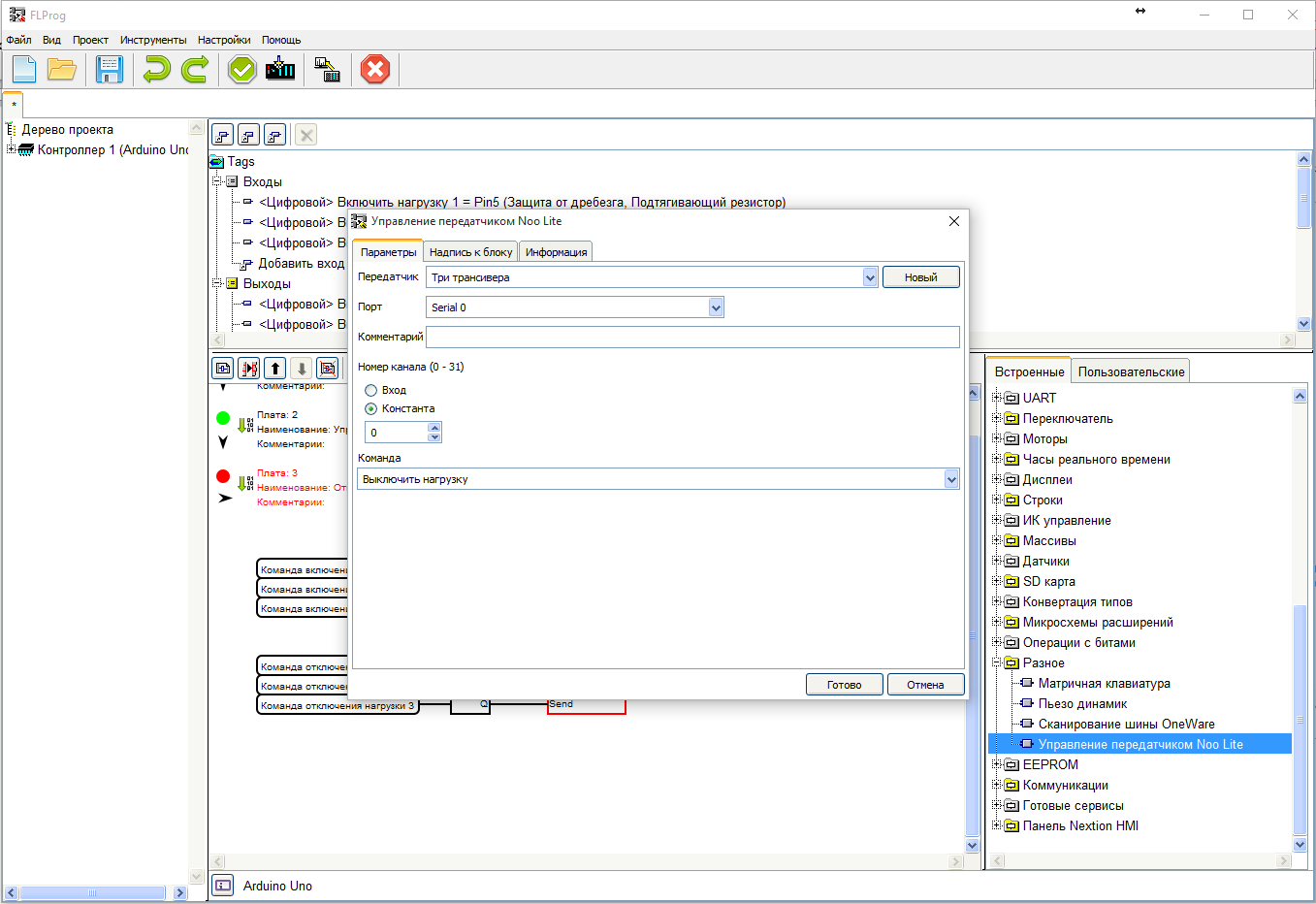
In accordance with the scheme, when a log.1 appears in any of the variables, a command will be sent to switch on the load. Configure the nooLite transceiver control unit to send this command.

Repeat this scheme to send a shutdown command.

Set up the block.
Well that's all. Thanks for attention.
Source: https://habr.com/ru/post/391837/
All Articles