What's inside? We disassemble the charger from the MacBook
Have you ever wondered what is inside the MacBook charger? In a compact power supply there is much more detail than one would expect, including even a microprocessor. In this article, you and I will be able to disassemble the MacBook charger to see the numerous components hidden inside and find out how they interact with each other to safely deliver much-needed electricity to the computer.
Most consumer electronics, from your smartphone to the TV, use switching power supplies to convert AC from a wall outlet to low-voltage DC used by electronic circuits. Switching power supplies or, more correctly speaking, low-voltage power supplies — got their name from the fact that they turn on and off the power supply thousands of times a second. It is most effective for voltage conversion.
')
The primary alternative to a switching power supply is a linear power supply that is much simpler and converts overvoltage into heat. Due to this loss of energy, the efficiency of a linear power supply is about 60%, compared with about 85% for a switching power supply. Linear power supplies use a bulky transformer that can weigh up to a kilogram or more, while switching power supplies can use tiny high-frequency transformers.
Now similar power sources are very cheap, but it was not always the case. In 1950, switching power supplies were complex and expensive, used in aerospace and satellite technologies that needed a light and compact power source. By the beginning of the 70s, new high-voltage transistors and other technological improvements made the sources much cheaper and became widely used in computers. The introduction of single-chip controllers in 1976 made it possible to make power converters even simpler, smaller and cheaper.
Apple's use of switching power supplies began in 1977, when Chief Engineer Rod Holt designed the switching power supply for the Apple II.
According to Steve Jobs:
This is an excellent quote, but it is not entirely correct. The revolution of power sources occurred much earlier. Robert Boschert (Robert Boschert), began selling switching power supplies in 1974 for everyone and everything, from printers and computers to the F-14 fighter. Apple's design was similar to earlier devices and other computers did not use the Rod Holt design. However, Apple has extensively used switching power supplies and is pushing the boundaries of the charger design with compact, stylish and advanced chargers.
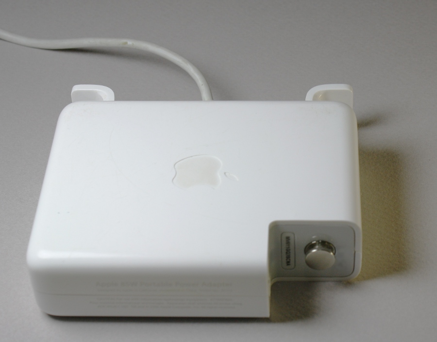
For analysis, a Macbook 85W model A1172 charger was taken, the dimensions of which are small enough to fit in the palm of your hand. The figure below shows several features that can help distinguish the original charger from fakes. A bitten apple on the case is an essential attribute (everyone knows about it), but there is a detail that does not always attract attention. Original chargers must always have a serial number located under the ground pin.
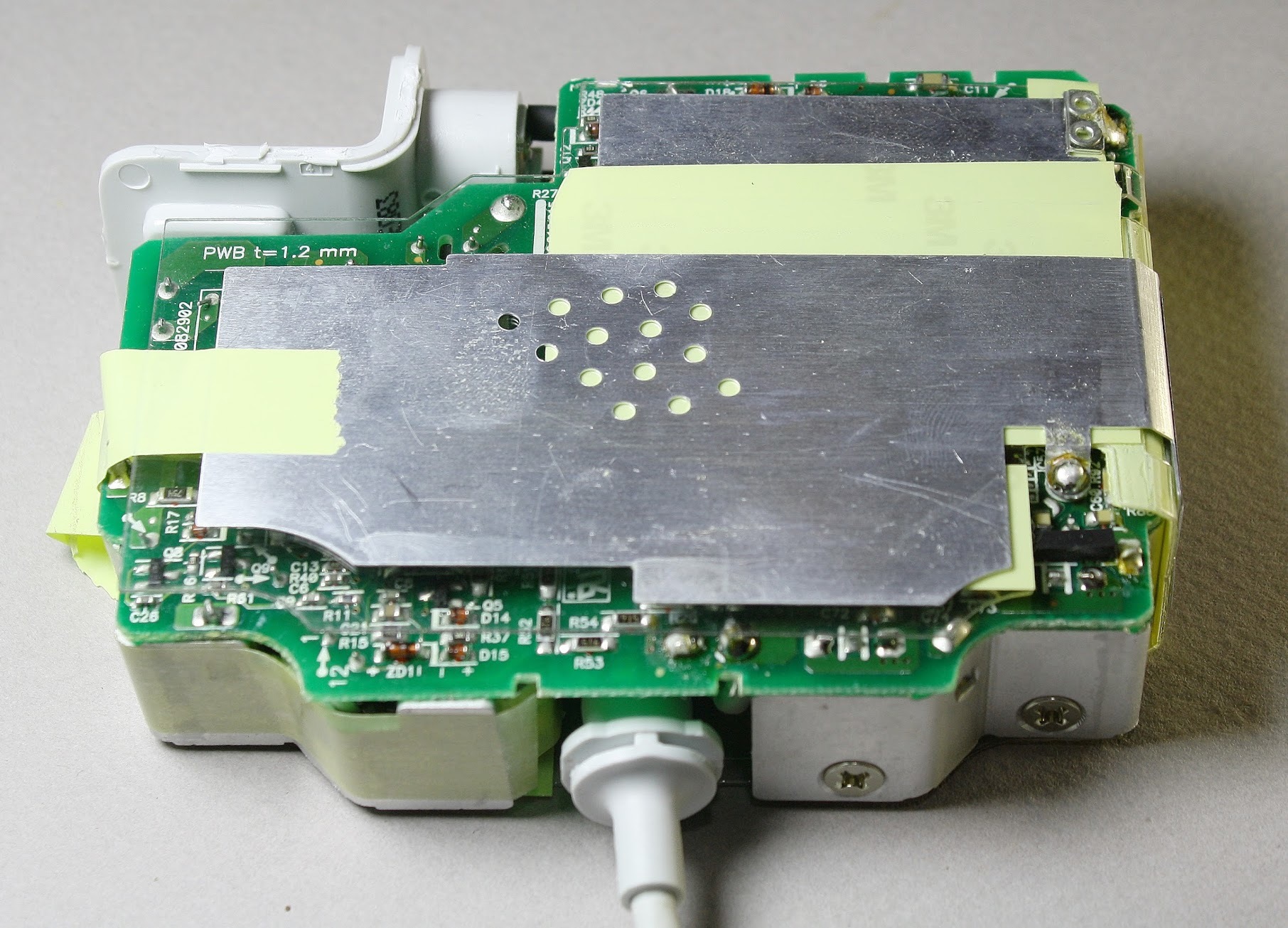
No matter how strange it may sound, the best way to open the charge is to use a chisel or something similar and add a little brute force to it. Apple initially opposed the fact that someone would open their products and inspect the "insides". Removing the plastic case, you can immediately see the metal radiators. They help cool powerful semiconductors placed inside the charger.

On the back of the charger you can see the PCB. Some tiny components are visible, but most of the circuit is hidden under a metal radiator, sealed with yellow electrical tape.
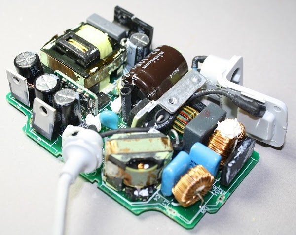
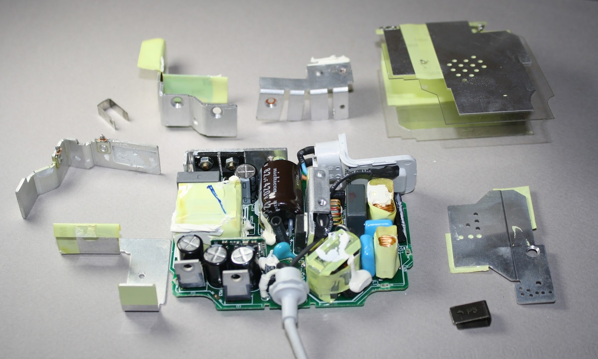
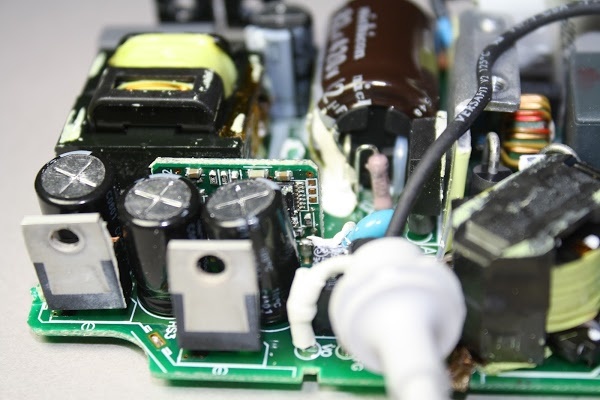
We looked at the radiators and that's enough. To see all the details of the device, of course you need to remove the radiators. Under these metal parts are hidden significantly more components than you would expect from a small block.
The image below shows the main components of the charger. AC power is supplied to the charger and already there is converted to direct current. The PFC (Power Factor Correction) scheme increases power efficiency by providing a steady load on the AC lines. In accordance with executable functions, it is possible to divide the board into two parts: high-voltage and low-voltage. The high-voltage part of the board, together with the components placed on it, is intended for lowering the high-voltage direct voltage and transmitting it to the transformer. The low-voltage part receives a constant low-voltage voltage from the transformer and outputs a constant-level voltage of the required level to the laptop. Below we consider these schemes in more detail.
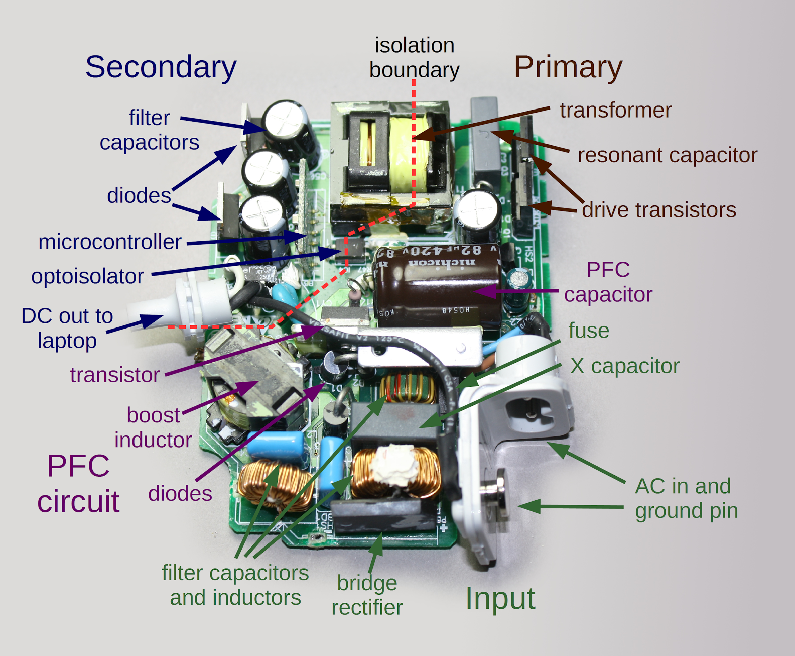
AC power is supplied to the charger via a removable mains plug. The great advantage of switching power supplies is their ability to operate over a wide range of incoming voltage. Just by changing the plug, the charger can be used in any region of the world, from European 240 volts at 50 hertz to North American 120 volts at a frequency of 60 hertz. Capacitors, filters and inductors at the input stage prevent interference from escaping from the charger through the power lines. A bridge rectifier contains four diodes that convert AC power to direct current.
Watch this video for a more visual demonstration of how a bridge rectifier works.

The next step in the operation of the charger is the power factor correction circuit, marked in purple. One of the problems with simple chargers is that they only charge in a small part of the AC cycle. When a single device does this, there are no particular problems, but when there are thousands of them, this creates problems for energy companies. That is why the rules require that chargers use power factor correction techniques (they use energy more evenly). You might expect a bad power factor caused by the transfer of switching power, which quickly turns on and off, but this is not a problem. The problem arises from a nonlinear diode bridge, which charges the input capacitor only with peaks of the AC signal. The idea of the PFC is to use a dc boost converter before switching power. Thus, the sinusoidal current output is proportional to the waveform of the alternating current.
The PFC circuit uses a power transistor to precisely crush the AC input tens of thousands of times per second. Contrary to expectations, this makes the load on the AC lines more smooth. The two largest components in the charger are the inductor and the PFC capacitor, which help to increase the DC voltage to 380 volts. The charger uses the MC33368 chip to run the PFC.
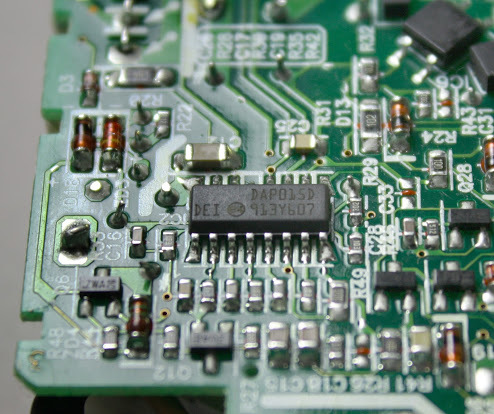
The high voltage circuit is the heart of the charger. It takes the high DC voltage from the PFC circuit, grinds it and feeds it into the transformer to generate a low voltage output from the charger (16.5-18.5 volts). The charger uses an advanced resonant controller that allows the system to operate at a very high frequency up to 500 kilohertz. Higher frequency allows more compact components to be used inside the charger. The microchip shown below controls the power supply.
Controller SMPS - high-voltage resonant controller L6599; For some reason, DAP015D is marked. It uses half-bridge resonance topology; in the half-bridge circuit, two transistors control the power through the converter. Common switching power supplies use PWM (pulse width modulation) controller, which adjusts the input time. L6599 corrects the frequency of the pulse and not its pulse. Both transistors are switched on alternately for 50% of the time. When the frequency increases above the resonant frequency, the power drops, so the frequency control adjusts the output voltage.
Two transistors are alternately turned on and off to reduce the input voltage. The transducer and capacitor resonate at the same frequency, smoothing the interrupted input to the sinusoidal wave.
The second half of the circuit generates the output of the charger. It receives power from the converter and with the help of diodes, converts it into direct current. Filter capacitors smooth out the voltage that comes from the charger through the cable.
The most important role of low-voltage parts of the charger is to keep dangerous high voltages inside the charger in order to avoid a potentially dangerous shock to the end device. An insulating gap marked with a red dotted line in the image above indicates a separation between the main high-voltage part and the low-voltage part of the device. Both sides are separated from each other at a distance of about 6 mm.
The transformer transfers power between the primary and secondary devices using magnetic fields, instead of a direct electrical connection. The wire in the transformer is triple insulated for safety. Cheap chargers are usually stingy with isolation. This creates a security risk. Optocoupler uses an internal beam of light to transmit a feedback signal between the low-voltage and high-voltage parts of the charger. The control chip in the high-voltage part of the device uses a feedback signal to adjust the switching frequency to keep the output voltage stable.
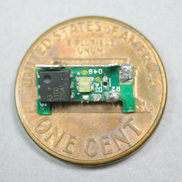
An unexpected component of the charger is a miniature printed circuit board with a microcontroller, which can be seen on our diagram above. This 16-bit processor continuously monitors the charger voltage and amperage. It turns on the transfer when the charger is connected to your MacBook and turns off the transfer when the charger is disconnected. Disconnecting the charger occurs if there is any problem. This Texas Instruments MSP430 microcontroller is about the same power as the processor inside the first original Macintosh. The processor in the charger is a low power microcontroller with 1 KB of flash memory and a total of 128 bytes of RAM. It includes a high-precision 16-bit analog-to-digital converter.
68000 microprocessor from the original Apple Macintosh and 430 microcontrollers in the charger are not comparable, because they have different designs and instruction sets. But for rough comparison: the 68000 is a 16/32 bit processor running at 7.8MHz, while the MSP430 is a 16 bit processor running at 16 MHz. The MSP430 is designed for low power consumption and uses approximately 1% of the power supply from the 68000.
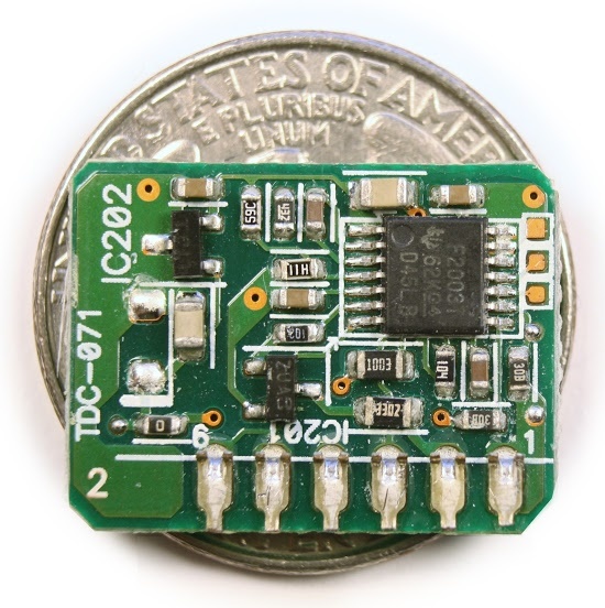
The gold-plated contact pads on the right are used to program the chip during production. The 60-watt MacBook charger uses an MSP430 processor, but the 85-watt charger uses a general-purpose processor, which must also be flashed. It is programmed with a Spy-Bi-Wire interface, which is a two-wire TI version of the standard JTAG interface. After programming, the safety fuse in the chip is destroyed to prevent reading or changing the firmware.
The three-pin chip on the left (IC202) reduces the 16.5 volts of the charger to the 3.3 volts required by the processor. The voltage on the processor is not provided by a standard voltage regulator, but by using the LT1460, which delivers 3.3 volts with an exceptionally high accuracy of 0.075%.
By turning the charger on the circuit board, you can see dozens of tiny components. Chip controllers PFC and power supply (SMPS) are the main integrated circuits that control the charger. The reference voltage source chip is responsible for maintaining a stable voltage even when the temperature changes. A reference voltage source chip, this is a TSM103 / A that combines two operational amplifiers and a 2.5-volt link in a single-chip circuit. The properties of a semiconductor vary considerably with temperature, so maintaining a stable voltage is not an easy task.
These chips are surrounded by tiny resistors, capacitors, diodes and other small components. MOSFET transistor, turns on and off the power at the output in accordance with the instructions of the microcontroller. To the left of it are resistors that measure the current transmitted to the laptop.

An isolation gap (marked in red) separates the high voltage from the low voltage output circuit for safety. The dashed red line indicates the isolation boundary that separates the low voltage side from the high voltage side. Optocouplers send signals from the low voltage side to the main device, disabling the charger if there are any problems.
A little bit about grounding. A 1KΩ grounding resistor connects the AC ground pin to the base of the charger output. Four 9.1MΩ resistors connect the internal DC base to the output core. Since they cross the isolation boundary, security is a problem. Their high resistance avoids the danger of shock. Four resistors are not really necessary, but redundancy exists in order to ensure the safety and resiliency of the device. There is also a Y capacitor (680pF, 250V) between internal ground and output ground. T5A fuse (5A) protects the grounding output.
One of the reasons to install more control components than usual in a charger is the alternating output voltage. To output 60 watts of voltage, the charger provides 16.5 volts with a resistance level of 3.6 ohms. For issuing 85 watts, the potential rises to 18.5 volts and the resistance is respectively 4.6 ohms. This allows the charger to be compatible with laptops that require different voltages. As the current potential increases above 3.6 amps, the circuit gradually increases the output voltage. The charger turns off when a voltage of 90 W is reached.
The control scheme is quite complex. The output voltage is controlled by the operational amplifier in the TSM103 / A microcircuit, which compares it to the reference voltage generated by the same microcircuit. This amplifier sends a feedback signal through the optocoupler to the SMPS control chip on the high voltage side. If the voltage is too high, the feedback signal lowers the voltage and vice versa. This is a fairly simple part, but where the voltage rises from 16.5 volts to 18.5 volts, everything becomes more complicated.
The output current creates a voltage on resistors with a tiny resistance of 0.005Ω each - they are more like wires than like resistors. The operational amplifier in the TSM103 / A microcircuit amplifies this voltage. This signal goes to the TS321 tiny operational amplifier, which triggers the build-up when the signal corresponds to 4.1A. This signal enters the previously described control circuit, increasing the output voltage. The current signal is also included in the tiny TS391 comparator, which sends a signal to a high-voltage device through another optocoupler to reduce the output voltage. This is a protection circuit if the current level becomes too high. There are several places on a printed circuit board where resistors with zero resistance (i.e., jumpers) can be installed to change the gain of the op amp. This allows you to adjust the gain accuracy during manufacturing.
The Magsafe magnetic plug that connects to your Macbook is more complicated than it might seem at first glance. It has five spring-loaded pins (known as pogo pins) for connecting to a computer, as well as two power contacts, two grounding pins. The middle pin is the data connection to the computer.

Inside Magsafe is a miniature chip that tells the laptop the serial number, type and power of the charger. The laptop uses this data to determine the originality of the charger. The chip also controls the LED indicator to visually determine the status. The laptop does not receive data directly from the charger, but only through a chip inside Magsafe.
You may have noticed that when you connect a charger to a laptop, it takes one or two seconds before the LED sensor triggers. During this time, there is a complex interaction between the Magsafe plug, the charger and the Macbook itself.
When the charger is disconnected from the laptop, the output transistor blocks the output voltage. If you measure the voltage from a MacBook charger, you will find about 6 volts instead of 16.5 volts that you hoped to see. The reason - the output is turned off, and you measure the voltage through a bypass resistor just below the output transistor. When the Magsafe plug is connected to your Macbook, it starts to turn on the low voltage level. The microcontroller in the charger detects this and turns on the power supply for a few seconds. During this time, the laptop manages to get all the necessary information about the charger from the chip inside Magsafe. If everything is fine, the laptop begins to consume power from the charger and sends a signal to the LED indicator. When the Magsafe plug is disconnected from the laptop, the microcontroller detects a loss of current and turns off the power supply, which also extinguishes the LEDs.
There is quite a logical question - why is the Apple charger so complicated? Other laptop chargers simply provide 16 volts and supply voltage immediately when connected to a computer. The main reason is for security reasons to ensure that the voltage is not applied until the contacts are firmly attached to the laptop. This minimizes the risk of a spark or electric arc arising when a Magsafe plug is connected.
The original Macbook 85W charger costs $ 79. But for $ 14 you can buy charging on eBay, which looks similar to the original. And so, what do you get for an extra $ 65? Let's compare the copy of the charger with the original. From the outside, the charger looks exactly like the original 85W from Apple. Except that the Apple logo itself is missing. But if you look inside, the differences become obvious. The photos below show the genuine Apple charger on the left and a copy on the right.

A copy of the charger has two times fewer parts than the original and the space on the printed circuit board is simply empty. While the genuine Apple charger is overflowing with components, its copy is not designed for more filtering and regulation and there is no PFC in it. The transformer in the copy of the charger (a large yellow rectangle) is much larger in size than the original model. The higher frequency of Apple's advanced resonant converter allows a smaller transformer to be used.
Turning over the charger and examining the printed circuit board, you can see a more complex diagram of the original charger. The copy has only one control IC (in the upper left corner). Since the PFC circuit is completely discarded. In addition, the charge clone is less complex to manage and does not have a ground connection. You understand what it threatens.
It is worth noting that the copy of the charger uses the Fairchild FAN7602 green PWM controller chip, which is more advanced than you would expect. I think most expected to see something like a simple transistor generator. And in addition to the copy, in contrast to the original, one-sided printed circuit board is used.
In fact, a copy of the charger is better quality than you would expect, compared to the terrible copies of the charger for iPad and iPhone. A copy of the charge for the MacBook does not reduce all possible components and uses a moderately complex scheme. This charger also places little emphasis on safety. Isolation of components and separation of sections of high and low voltage are applied, with the exception of one dangerous error, which you will see below. The capacitor Y (blue) was installed crookedly and dangerously close to the contact of the optocoupler on the high voltage side, creating the risk of electric shock.

The irony is that despite the complexity and attention to detail, the Apple MacBook charger is not a trouble-free device. On the Internet you can find a lot of different photos of burnt, damaged and just non-working charge. The most vulnerable part of the original charger is the wire in the area of the Magsafe plug. The cable is rather flimsy and it is quickly frayed, which causes it to be damaged, burned out or just perelamyvaniyu. Apple provides detailed instructions on how to avoid cable damage, instead of just providing a more powerful cable. As a result of a review on the Apple website, the charger received only 1.5 stars out of a possible 5.

MacBook chargers may also stop working due to internal problems. The photos above and below show the burn marks inside Apple's unsuccessful charging. It is impossible to say exactly what exactly caused the fire, alas. Due to a short circuit, half of the components and a good part of the printed circuit board burned down. At the bottom of the photo is burnt silicone insulation for mounting the board.
As you can see, Apple's charger has a more advanced design than copies and has additional security features. However, a genuine charger costs $ 65 more and I doubt that additional components cost more than $ 10- $ 15. Most of the cost of a charger goes into the company's net profit. The estimated cost of an iPhone of 45% is the company's net profit. Chargers probably bring even more money. The price of the original from Apple should be significantly lower. The device has many tiny components of resistors, capacitors and transistors, the price of which varies in the region of one cent. Large semiconductors, capacitors and inductors naturally cost significantly more, but for example, a 16-bit MSP430 processor costs only $ 0.45. Apple explains the high cost not only of marketing costs and so on, but also the high costs of developing one or another charging model. The book Practical Switching Power Supply Design estimates 9 months of working time to design and improve power supplies in the region of $ 200,000. The company sells about 20 million MacBooks in a year. If you invest the cost of development in the cost of the device, it will be only 1 cent. Even if the cost of the design and development of chargers from Apple is 10 times higher, the price will not exceed 10 cents. Despite all this, I do not recommend that you save your money by purchasing analogs of the charger and risking your laptop and even your health.
Users are not often interested in what is inside the charger. But it is full of interesting things. A seemingly simple charge uses advanced technology, including power factor corrections and a resonant power supply, to produce 85 watts of power in a compact unit. The Macbook charger is an impressive piece of engineering. At the same time, its copies tend to make it as cheap as possible. This is of course economical, but also a danger to you and your laptop.
Most consumer electronics, from your smartphone to the TV, use switching power supplies to convert AC from a wall outlet to low-voltage DC used by electronic circuits. Switching power supplies or, more correctly speaking, low-voltage power supplies — got their name from the fact that they turn on and off the power supply thousands of times a second. It is most effective for voltage conversion.
')
The primary alternative to a switching power supply is a linear power supply that is much simpler and converts overvoltage into heat. Due to this loss of energy, the efficiency of a linear power supply is about 60%, compared with about 85% for a switching power supply. Linear power supplies use a bulky transformer that can weigh up to a kilogram or more, while switching power supplies can use tiny high-frequency transformers.
Now similar power sources are very cheap, but it was not always the case. In 1950, switching power supplies were complex and expensive, used in aerospace and satellite technologies that needed a light and compact power source. By the beginning of the 70s, new high-voltage transistors and other technological improvements made the sources much cheaper and became widely used in computers. The introduction of single-chip controllers in 1976 made it possible to make power converters even simpler, smaller and cheaper.
Apple's use of switching power supplies began in 1977, when Chief Engineer Rod Holt designed the switching power supply for the Apple II.
According to Steve Jobs:
This switching power supply was as revolutionary as the Apple II logic. Rod did not receive much recognition in the pages of history, but he deserved it. Every computer now uses switching power supplies and they are all similar in structure to that invented by Holt.
This is an excellent quote, but it is not entirely correct. The revolution of power sources occurred much earlier. Robert Boschert (Robert Boschert), began selling switching power supplies in 1974 for everyone and everything, from printers and computers to the F-14 fighter. Apple's design was similar to earlier devices and other computers did not use the Rod Holt design. However, Apple has extensively used switching power supplies and is pushing the boundaries of the charger design with compact, stylish and advanced chargers.
What's inside?
For analysis, a Macbook 85W model A1172 charger was taken, the dimensions of which are small enough to fit in the palm of your hand. The figure below shows several features that can help distinguish the original charger from fakes. A bitten apple on the case is an essential attribute (everyone knows about it), but there is a detail that does not always attract attention. Original chargers must always have a serial number located under the ground pin.
No matter how strange it may sound, the best way to open the charge is to use a chisel or something similar and add a little brute force to it. Apple initially opposed the fact that someone would open their products and inspect the "insides". Removing the plastic case, you can immediately see the metal radiators. They help cool powerful semiconductors placed inside the charger.
On the back of the charger you can see the PCB. Some tiny components are visible, but most of the circuit is hidden under a metal radiator, sealed with yellow electrical tape.
We looked at the radiators and that's enough. To see all the details of the device, of course you need to remove the radiators. Under these metal parts are hidden significantly more components than you would expect from a small block.
The image below shows the main components of the charger. AC power is supplied to the charger and already there is converted to direct current. The PFC (Power Factor Correction) scheme increases power efficiency by providing a steady load on the AC lines. In accordance with executable functions, it is possible to divide the board into two parts: high-voltage and low-voltage. The high-voltage part of the board, together with the components placed on it, is intended for lowering the high-voltage direct voltage and transmitting it to the transformer. The low-voltage part receives a constant low-voltage voltage from the transformer and outputs a constant-level voltage of the required level to the laptop. Below we consider these schemes in more detail.
AC inlet charger
AC power is supplied to the charger via a removable mains plug. The great advantage of switching power supplies is their ability to operate over a wide range of incoming voltage. Just by changing the plug, the charger can be used in any region of the world, from European 240 volts at 50 hertz to North American 120 volts at a frequency of 60 hertz. Capacitors, filters and inductors at the input stage prevent interference from escaping from the charger through the power lines. A bridge rectifier contains four diodes that convert AC power to direct current.
Watch this video for a more visual demonstration of how a bridge rectifier works.
PFC: power smoothing
The next step in the operation of the charger is the power factor correction circuit, marked in purple. One of the problems with simple chargers is that they only charge in a small part of the AC cycle. When a single device does this, there are no particular problems, but when there are thousands of them, this creates problems for energy companies. That is why the rules require that chargers use power factor correction techniques (they use energy more evenly). You might expect a bad power factor caused by the transfer of switching power, which quickly turns on and off, but this is not a problem. The problem arises from a nonlinear diode bridge, which charges the input capacitor only with peaks of the AC signal. The idea of the PFC is to use a dc boost converter before switching power. Thus, the sinusoidal current output is proportional to the waveform of the alternating current.
The PFC circuit uses a power transistor to precisely crush the AC input tens of thousands of times per second. Contrary to expectations, this makes the load on the AC lines more smooth. The two largest components in the charger are the inductor and the PFC capacitor, which help to increase the DC voltage to 380 volts. The charger uses the MC33368 chip to run the PFC.
Primary power conversion
The high voltage circuit is the heart of the charger. It takes the high DC voltage from the PFC circuit, grinds it and feeds it into the transformer to generate a low voltage output from the charger (16.5-18.5 volts). The charger uses an advanced resonant controller that allows the system to operate at a very high frequency up to 500 kilohertz. Higher frequency allows more compact components to be used inside the charger. The microchip shown below controls the power supply.
Controller SMPS - high-voltage resonant controller L6599; For some reason, DAP015D is marked. It uses half-bridge resonance topology; in the half-bridge circuit, two transistors control the power through the converter. Common switching power supplies use PWM (pulse width modulation) controller, which adjusts the input time. L6599 corrects the frequency of the pulse and not its pulse. Both transistors are switched on alternately for 50% of the time. When the frequency increases above the resonant frequency, the power drops, so the frequency control adjusts the output voltage.
Two transistors are alternately turned on and off to reduce the input voltage. The transducer and capacitor resonate at the same frequency, smoothing the interrupted input to the sinusoidal wave.
Secondary power conversion
The second half of the circuit generates the output of the charger. It receives power from the converter and with the help of diodes, converts it into direct current. Filter capacitors smooth out the voltage that comes from the charger through the cable.
The most important role of low-voltage parts of the charger is to keep dangerous high voltages inside the charger in order to avoid a potentially dangerous shock to the end device. An insulating gap marked with a red dotted line in the image above indicates a separation between the main high-voltage part and the low-voltage part of the device. Both sides are separated from each other at a distance of about 6 mm.
The transformer transfers power between the primary and secondary devices using magnetic fields, instead of a direct electrical connection. The wire in the transformer is triple insulated for safety. Cheap chargers are usually stingy with isolation. This creates a security risk. Optocoupler uses an internal beam of light to transmit a feedback signal between the low-voltage and high-voltage parts of the charger. The control chip in the high-voltage part of the device uses a feedback signal to adjust the switching frequency to keep the output voltage stable.
Powerful microprocessor inside the charger
An unexpected component of the charger is a miniature printed circuit board with a microcontroller, which can be seen on our diagram above. This 16-bit processor continuously monitors the charger voltage and amperage. It turns on the transfer when the charger is connected to your MacBook and turns off the transfer when the charger is disconnected. Disconnecting the charger occurs if there is any problem. This Texas Instruments MSP430 microcontroller is about the same power as the processor inside the first original Macintosh. The processor in the charger is a low power microcontroller with 1 KB of flash memory and a total of 128 bytes of RAM. It includes a high-precision 16-bit analog-to-digital converter.
68000 microprocessor from the original Apple Macintosh and 430 microcontrollers in the charger are not comparable, because they have different designs and instruction sets. But for rough comparison: the 68000 is a 16/32 bit processor running at 7.8MHz, while the MSP430 is a 16 bit processor running at 16 MHz. The MSP430 is designed for low power consumption and uses approximately 1% of the power supply from the 68000.
The gold-plated contact pads on the right are used to program the chip during production. The 60-watt MacBook charger uses an MSP430 processor, but the 85-watt charger uses a general-purpose processor, which must also be flashed. It is programmed with a Spy-Bi-Wire interface, which is a two-wire TI version of the standard JTAG interface. After programming, the safety fuse in the chip is destroyed to prevent reading or changing the firmware.
The three-pin chip on the left (IC202) reduces the 16.5 volts of the charger to the 3.3 volts required by the processor. The voltage on the processor is not provided by a standard voltage regulator, but by using the LT1460, which delivers 3.3 volts with an exceptionally high accuracy of 0.075%.
Lots of tiny components on the bottom of the charger
By turning the charger on the circuit board, you can see dozens of tiny components. Chip controllers PFC and power supply (SMPS) are the main integrated circuits that control the charger. The reference voltage source chip is responsible for maintaining a stable voltage even when the temperature changes. A reference voltage source chip, this is a TSM103 / A that combines two operational amplifiers and a 2.5-volt link in a single-chip circuit. The properties of a semiconductor vary considerably with temperature, so maintaining a stable voltage is not an easy task.
These chips are surrounded by tiny resistors, capacitors, diodes and other small components. MOSFET transistor, turns on and off the power at the output in accordance with the instructions of the microcontroller. To the left of it are resistors that measure the current transmitted to the laptop.
An isolation gap (marked in red) separates the high voltage from the low voltage output circuit for safety. The dashed red line indicates the isolation boundary that separates the low voltage side from the high voltage side. Optocouplers send signals from the low voltage side to the main device, disabling the charger if there are any problems.
A little bit about grounding. A 1KΩ grounding resistor connects the AC ground pin to the base of the charger output. Four 9.1MΩ resistors connect the internal DC base to the output core. Since they cross the isolation boundary, security is a problem. Their high resistance avoids the danger of shock. Four resistors are not really necessary, but redundancy exists in order to ensure the safety and resiliency of the device. There is also a Y capacitor (680pF, 250V) between internal ground and output ground. T5A fuse (5A) protects the grounding output.
One of the reasons to install more control components than usual in a charger is the alternating output voltage. To output 60 watts of voltage, the charger provides 16.5 volts with a resistance level of 3.6 ohms. For issuing 85 watts, the potential rises to 18.5 volts and the resistance is respectively 4.6 ohms. This allows the charger to be compatible with laptops that require different voltages. As the current potential increases above 3.6 amps, the circuit gradually increases the output voltage. The charger turns off when a voltage of 90 W is reached.
The control scheme is quite complex. The output voltage is controlled by the operational amplifier in the TSM103 / A microcircuit, which compares it to the reference voltage generated by the same microcircuit. This amplifier sends a feedback signal through the optocoupler to the SMPS control chip on the high voltage side. If the voltage is too high, the feedback signal lowers the voltage and vice versa. This is a fairly simple part, but where the voltage rises from 16.5 volts to 18.5 volts, everything becomes more complicated.
The output current creates a voltage on resistors with a tiny resistance of 0.005Ω each - they are more like wires than like resistors. The operational amplifier in the TSM103 / A microcircuit amplifies this voltage. This signal goes to the TS321 tiny operational amplifier, which triggers the build-up when the signal corresponds to 4.1A. This signal enters the previously described control circuit, increasing the output voltage. The current signal is also included in the tiny TS391 comparator, which sends a signal to a high-voltage device through another optocoupler to reduce the output voltage. This is a protection circuit if the current level becomes too high. There are several places on a printed circuit board where resistors with zero resistance (i.e., jumpers) can be installed to change the gain of the op amp. This allows you to adjust the gain accuracy during manufacturing.
Magsafe plug
The Magsafe magnetic plug that connects to your Macbook is more complicated than it might seem at first glance. It has five spring-loaded pins (known as pogo pins) for connecting to a computer, as well as two power contacts, two grounding pins. The middle pin is the data connection to the computer.
Inside Magsafe is a miniature chip that tells the laptop the serial number, type and power of the charger. The laptop uses this data to determine the originality of the charger. The chip also controls the LED indicator to visually determine the status. The laptop does not receive data directly from the charger, but only through a chip inside Magsafe.
Charger use
You may have noticed that when you connect a charger to a laptop, it takes one or two seconds before the LED sensor triggers. During this time, there is a complex interaction between the Magsafe plug, the charger and the Macbook itself.
When the charger is disconnected from the laptop, the output transistor blocks the output voltage. If you measure the voltage from a MacBook charger, you will find about 6 volts instead of 16.5 volts that you hoped to see. The reason - the output is turned off, and you measure the voltage through a bypass resistor just below the output transistor. When the Magsafe plug is connected to your Macbook, it starts to turn on the low voltage level. The microcontroller in the charger detects this and turns on the power supply for a few seconds. During this time, the laptop manages to get all the necessary information about the charger from the chip inside Magsafe. If everything is fine, the laptop begins to consume power from the charger and sends a signal to the LED indicator. When the Magsafe plug is disconnected from the laptop, the microcontroller detects a loss of current and turns off the power supply, which also extinguishes the LEDs.
There is quite a logical question - why is the Apple charger so complicated? Other laptop chargers simply provide 16 volts and supply voltage immediately when connected to a computer. The main reason is for security reasons to ensure that the voltage is not applied until the contacts are firmly attached to the laptop. This minimizes the risk of a spark or electric arc arising when a Magsafe plug is connected.
Why you should not use cheap chargers
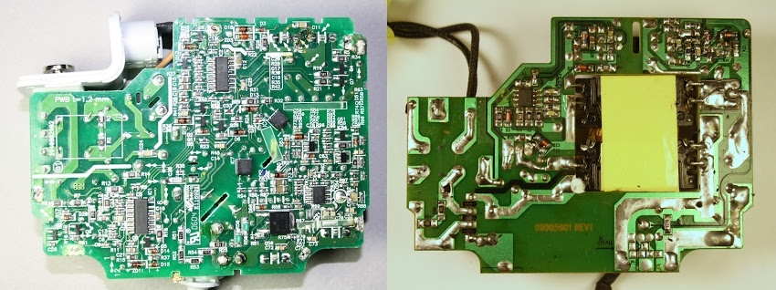
The original Macbook 85W charger costs $ 79. But for $ 14 you can buy charging on eBay, which looks similar to the original. And so, what do you get for an extra $ 65? Let's compare the copy of the charger with the original. From the outside, the charger looks exactly like the original 85W from Apple. Except that the Apple logo itself is missing. But if you look inside, the differences become obvious. The photos below show the genuine Apple charger on the left and a copy on the right.
A copy of the charger has two times fewer parts than the original and the space on the printed circuit board is simply empty. While the genuine Apple charger is overflowing with components, its copy is not designed for more filtering and regulation and there is no PFC in it. The transformer in the copy of the charger (a large yellow rectangle) is much larger in size than the original model. The higher frequency of Apple's advanced resonant converter allows a smaller transformer to be used.
Turning over the charger and examining the printed circuit board, you can see a more complex diagram of the original charger. The copy has only one control IC (in the upper left corner). Since the PFC circuit is completely discarded. In addition, the charge clone is less complex to manage and does not have a ground connection. You understand what it threatens.
It is worth noting that the copy of the charger uses the Fairchild FAN7602 green PWM controller chip, which is more advanced than you would expect. I think most expected to see something like a simple transistor generator. And in addition to the copy, in contrast to the original, one-sided printed circuit board is used.
In fact, a copy of the charger is better quality than you would expect, compared to the terrible copies of the charger for iPad and iPhone. A copy of the charge for the MacBook does not reduce all possible components and uses a moderately complex scheme. This charger also places little emphasis on safety. Isolation of components and separation of sections of high and low voltage are applied, with the exception of one dangerous error, which you will see below. The capacitor Y (blue) was installed crookedly and dangerously close to the contact of the optocoupler on the high voltage side, creating the risk of electric shock.
Apple Original Issues
The irony is that despite the complexity and attention to detail, the Apple MacBook charger is not a trouble-free device. On the Internet you can find a lot of different photos of burnt, damaged and just non-working charge. The most vulnerable part of the original charger is the wire in the area of the Magsafe plug. The cable is rather flimsy and it is quickly frayed, which causes it to be damaged, burned out or just perelamyvaniyu. Apple provides detailed instructions on how to avoid cable damage, instead of just providing a more powerful cable. As a result of a review on the Apple website, the charger received only 1.5 stars out of a possible 5.
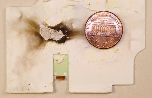
MacBook chargers may also stop working due to internal problems. The photos above and below show the burn marks inside Apple's unsuccessful charging. It is impossible to say exactly what exactly caused the fire, alas. Due to a short circuit, half of the components and a good part of the printed circuit board burned down. At the bottom of the photo is burnt silicone insulation for mounting the board.
Why are original chargers so expensive?
As you can see, Apple's charger has a more advanced design than copies and has additional security features. However, a genuine charger costs $ 65 more and I doubt that additional components cost more than $ 10- $ 15. Most of the cost of a charger goes into the company's net profit. The estimated cost of an iPhone of 45% is the company's net profit. Chargers probably bring even more money. The price of the original from Apple should be significantly lower. The device has many tiny components of resistors, capacitors and transistors, the price of which varies in the region of one cent. Large semiconductors, capacitors and inductors naturally cost significantly more, but for example, a 16-bit MSP430 processor costs only $ 0.45. Apple explains the high cost not only of marketing costs and so on, but also the high costs of developing one or another charging model. The book Practical Switching Power Supply Design estimates 9 months of working time to design and improve power supplies in the region of $ 200,000. The company sells about 20 million MacBooks in a year. If you invest the cost of development in the cost of the device, it will be only 1 cent. Even if the cost of the design and development of chargers from Apple is 10 times higher, the price will not exceed 10 cents. Despite all this, I do not recommend that you save your money by purchasing analogs of the charger and risking your laptop and even your health.
| Component | Price |
|---|---|
| MSP430F2003 processor | $ 0.45 |
| MC33368D PFC chip | $ 0.50 |
| L6599 controller | $ 1.62 |
| LT1460 3.3V | $ 1.46 |
| TSM103 / A | $ 0.16 |
| 2x P11NM60AFP 11A 60V MOSFET | $ 2.00 |
| 3x Vishay Optocoupler | $ 0.48 |
| 2x 630V 0.47uF film capacitor | $ 0.88 |
| 4x 25V 680uF electrolytic capacitor | $ 0.12 |
| 420V 82uF electrolytic capacitor | $ 0.93 |
| polypropylene capacitor X2 | $ 0.17 |
| 3x toroidal inductor | $ 0.75 |
| 4A 600V diode bridge | $ 0.40 |
| 2x semiconductor diode Schottky 60V, 15A | $ 0.80 |
| 20NC603 MOSFET | $ 1.57 |
| transformer | $ 1.50 |
| PFC inductor | $ 1.50 |
And for the remainder
Users are not often interested in what is inside the charger. But it is full of interesting things. A seemingly simple charge uses advanced technology, including power factor corrections and a resonant power supply, to produce 85 watts of power in a compact unit. The Macbook charger is an impressive piece of engineering. At the same time, its copies tend to make it as cheap as possible. This is of course economical, but also a danger to you and your laptop.
Source: https://habr.com/ru/post/391813/
All Articles