FLProg + nooLite
First of all, I want to warn you that this is not an advertising post, I have nothing to do with the company - the manufacturer of the equipment described in the article, and I don’t have any cookies from it except for the equipment provided for integration into the program. This is a training post that shows how to use FLProg to manage this equipment. Naturally there will be a small overview of the blocks I have and my personal attitude to these devices.
Now a little background. One of the users of the program turned to Nootekhnika with a proposal to create a user unit (at that time the program already had such an opportunity) to work with the equipment produced by them through the FLProg program. The head of the company went the other way. He contacted me and offered to provide me with samples of his products for integrating them into the program. After reviewing the proposal, I agreed, because the site had a library for working with the transmitter module, there was a good description, and I did not see any problems. The parcel arrived very quickly (which is strange for Russian post), even considering the border crossing.
What has come:
')
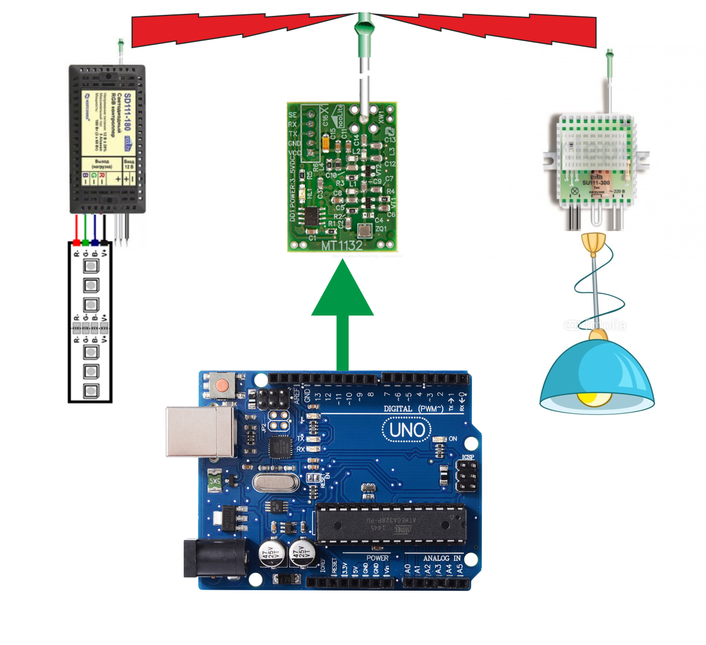
MT1132 transmitter module

The MT1132 module is designed to control the power units of the nooLite system from the Arduino platform, microcontrollers or PC.
Structurally, the module is made in the form of a printed circuit board, on which the control controller and transmitter are located.
The module is controlled via a serial UART interface. The module transmits commands received via the UART to the power blocks via the built-in radio transmitter.
Power unit SD111-180

Radio-controlled LED RGB controller (power unit) nooLite SD111-180 is designed to control the LED strip at 12 V. The LED strip can be either three-color (RGB) or single-color.
Power unit SU111-300

The power unit SU111-300 is a universal radio switch designed for remote on / off lighting with the ability to adjust the brightness for dimmable light sources (incandescent lamps, LED dimmable lamps). The unit can operate in two modes: relay and dimming, depending on the intended type of load. In relay mode, the SU111 300 is able to work with any type of load.
More information about these devices can be found on the manufacturer's website.
The blocks are made very high quality. I suspect that the enterprise works on the basis of a former Soviet enterprise, and in Soviet times, Belarus produced good equipment. Although maybe I'm wrong.
The system of switching on the binding of power units was originally implemented. To enable this mode, it is necessary to compress the body at a certain point, and the microswitch inside will operate. But in the instructions this place is clearly shown, so I hit the first time.
The first switching on of the transmitter made you feel a little nervous. When power was applied to the board, nothing lit up, although there is an LED on the board. I'm used to the fact that there is an indication of the presence of power on all devices. On this transmitter it is not. I even decided at first that the board was not working, and I used a tester to measure voltages. But everything seems to be in order. Then I downloaded the library from the site, and started trying examples. The LED blinks when sending a command. At the same time there is a subtlety. He blinks not when receiving data on UART, namely when sending command in the air. This feature is the same made nervous. Already during the development of the compiler, the commands to the power units suddenly ceased to pass, and the LED stopped blinking. Although I clearly saw that the packages on the UART go. I decided that I still burned him. It turned out that the error in the code, and the checksum that is present in the package, I had incorrectly calculated. Accordingly, the transmitter did not accept this packet and did not send commands. After fixing the code, everything worked fine.
Now about the library, which lies on the manufacturer's website. I originally planned to use it. But picking on her, I realized that she did not like me. Firstly, it does not support operation with a LED ribbon controller (SD111-180). Second, she does not know how to control the dimming mode for the power unit (SU111 300). And finally, it is nailed to the SoftwareSerial. This is not always good. Still, in some cases it is better to use a hardware UART to save resources. Therefore, I had to develop the code myself (naturally looking at the library implementation).
In all other respects, this equipment left a very pleasant impression. It works stably, there are many possibilities, the quality is at a very high level. For the price is certainly higher than the usual equipment from China. But there are no analogues in China yet (at least I haven’t found the same complex), but compared to far-abroad countries where such systems are produced, the price is even very attractive.
Well, now let's look at the implementation of the transmitter control through the FLProg program.
Connect the transmitter to the Arduino in accordance with the scheme.
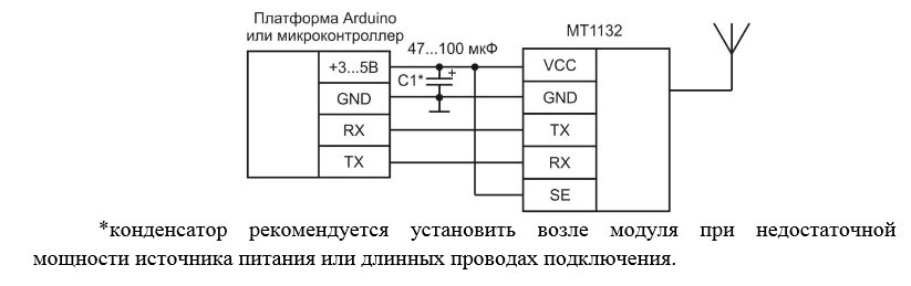
The RX (Arduino) - TX (MT1132) connection can be not used, since I did not implement the feedback from the transmitter to the controller (confirmation of sending the command). The elimination of this connection allows using the hardware UART not to turn off the transmitter when pouring the controller.
To control the transmitter in the FLProg program, the block “Control of the transmitter Noo Lite” (folder “Miscellaneous”) appeared in the library of elements.


Sending commands to the transmitter occurs on the leading edge of the pulse at the input «Send». For each command, you can use a separate block, or the command can be set to the value supplied to the input "Comand".
Like all the others, this block is configured using the block editor (called by double clicking on the block transferred to the workspace of the scheme).
If you parameterize the first such block in the circuit, then you need to connect a new transmitter.

This will open the transmitter connection window.

In this window, you must specify the name of the transmitter and select the port to which it is connected. In the case of using SoftwareSerial, it is also necessary to choose pins for this port.
After connecting the transmitter, it is necessary to establish the channel on which the command will be transmitted.
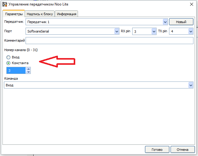
The channel can be set as a constant, so use the input for this. Accordingly, when using the input, the channel can be changed programmatically.
And finally, we choose the command to be sent.

List of supported commands:
- Tie receiver
- Unlink receiver
- Enable load
- Turn off the load
- Toggle state
- Start smooth dimming
- Run smooth brightness enhancement
- Change the direction of the smooth change in brightness
- Stop smooth dimming
- Set the brightness (0 - 120)
- Enable smooth search of colors (only for LED ribbon controller)
- Toggle color (only for LED ribbon controller)
- Switch operation mode (only for LED ribbon controller)
- Toggle effect speed (only for LED ribbon controller)
- Set the brightness for each channel (0-255) (only for the ribbon LED controller)
- Remember state
- Set Saved State
To select a command, you can also use the input (select “Input” in the list of commands) and in this case, during the program execution, you can change the command by inputting “Comand” its number to the input.
Command Numbers:
| Team number | Team |
|---|---|
| 0 | Enable load |
| one | Start smooth dimming |
| 2 | Turn off the load |
| 3 | Run smooth brightness enhancement |
| four | Toggle state |
| five | Change the direction of the smooth change in brightness |
| 7 | Set Saved State |
| eight | Remember state |
| 9 | Unlink receiver |
| ten | Stop smooth dimming |
| 15 | Tie receiver |
| sixteen | Enable smooth search of colors (only for LED ribbon controller) |
| 17 | Toggle color (only for LED ribbon controller) |
| 18 | Switch operation mode (only for LED ribbon controller) |
| nineteen | Toggle effect speed (only for LED ribbon controller) |
Please note that in this table there are no “ Set brightness (0 - 120) ” and “Set brightness for each channel (0-255) (only for LED ribbon controller)” commands. To send these commands, you must use a separate block. Let's look at these commands in more detail.
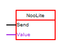
“ Set brightness (0 - 120) ” - if you select this command, additional parameters will appear in the block editor.
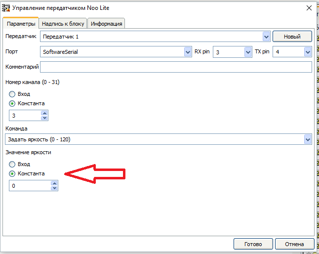
Using these parameters, you can set the brightness value transmitted as a constant in the command or use the input. In the second case of the input, the block will have the input “ Value ”
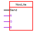
“ Set the brightness for each channel (0-255) (only for the LED ribbon controller) ” - if you select this command in the block editor, additional parameters will also appear.
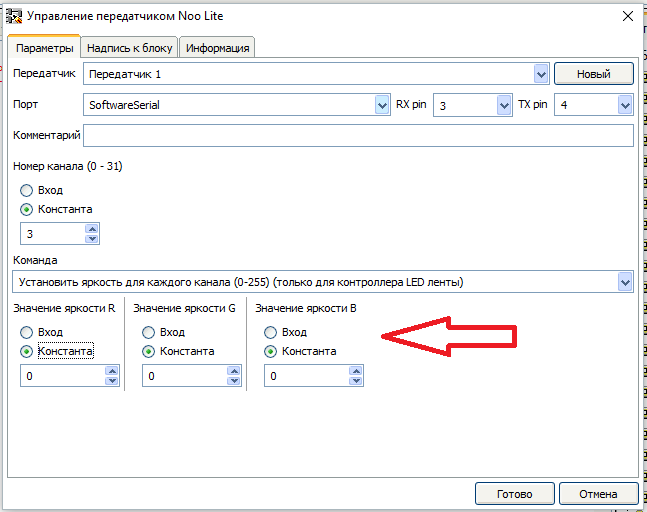
And just like in the previous command, the brightness value for each channel can be set either as a constant or as an input. At the same time, the block will have the corresponding inputs - “ R ”, “ G ”, “ B ”
Well, probably, and that's all, thank you for your attention.
Source: https://habr.com/ru/post/391477/
All Articles