Wireless wit. Overview module ESP-8266 Witty
During its still short existence, ESP8266 managed to mutate into many modifications of various sizes and shapes with different capabilities.
And now, from the Celestial Empire, I came to a headscarf based on it, which I had never had to hold in my hands before. In something interesting, in something funny. Let's figure it out.
This board has a proper name: Witty. Yeah, the wits of the creators, the Chinese company Gizwits, just do not hold.
In general, Gizwits is positioning itself as a provider of solutions for the smart home, whatever that means.
Among other things, this company has its own cloud for the Internet of things, which also includes remote management. Accordingly, there is support for a number of wireless devices. Including the ESP 8266 in such an unusual version.
')
For those who are too lazy to read, the video version of this material:
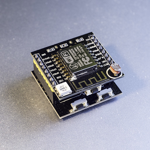
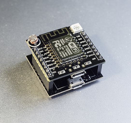
The most interesting thing in the design of this module is that it consists of two separate boards: the controller board itself and the auxiliary one used for firmware and communication with the computer.
Consider them separately.
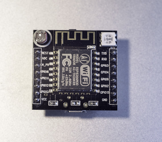
We immediately see that the module is assembled on the basis of ESP-12. The description indicates that the latest ESP-12F model is used at the time of release of this material. Whether this is so, I can not say, because it is difficult to visually distinguish between ESP-12E and ESP-12F.
Divided all the findings of the ESP-12, and divorced c increments of one-tenth of an inch, which will easily mount it on common layout. Also installed on the module:
- light sensor. A simple photoresistor connected to the analog input through a divider;
- RGB SMD5050 format LED;
- button, apparently connected to GPIO4.
Unobvious moment
On the leg of the Vcc of our module is not 3.3V, as one would assume, but 5V. And they go directly from the LM1117, which allows to feed significant loads from the Vcc foot. If you need 3.3V, you can take them from the foot CH_PD.
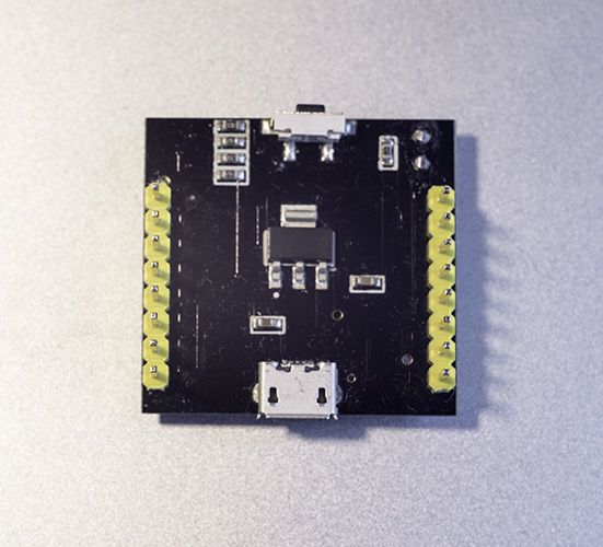
On the bottom side of the board we see:
- microUSB-connector used for power;
- Converter 1117, reducing coming with microUSB 5V to 3.3V;
- body kit for LEDs, and light sensor.
Second board
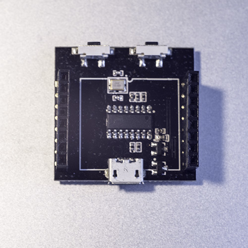
It seems that it was planned as a Shield for firmware. It shows another microUSB connector, the ch340 chip, a USB-UART converter and buttons, labeled RESET and FLASH.
Thus, it can be assumed that, according to the manufacturer's idea, all wired communication with this module should pass through this Shield. It is strange then why this Shield is not made through, to give the opportunity to plant it directly on the breadboard. It turns out that for each firmware update the module will have to be removed from the circuit, which is not very convenient.
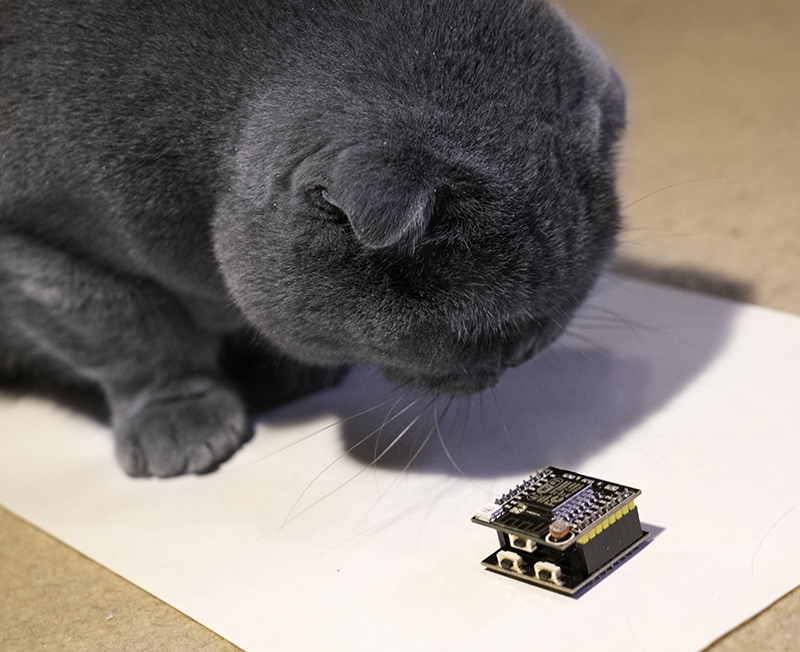
Another surprise awaits us when trying to install this module in the layout.
The module occupies the entire width of the brainboard. Accordingly, it becomes difficult to switch something with wires with dupont connectors. Or rather, altogether impossible. The only solution that comes to my mind is to connect several prototypes in parallel and connect the module to both at once.
We figured out the design, now we feed the microUSB board to the module and see what happens.
The LED lights up - it means the module is working. Conveniently, no additional power supply units are needed, because the 500 milliamperes that the usb port issues are enough for the module.
After launching the module, I expected to see a new network, which by default all 8266s create on the standard firmware, but this did not happen, new networks were not detected in radius of visibility. Strange ...
Having connected to the module via the wire using the ESPlorer utility (I use it to communicate with the board by habit), I got something unintelligible to the console.
It looks like non-standard firmware.
Well, I'm not going to connect to the Chinese cloud, so I’m going to get a module with something more suitable. For example, NodeMCU.
To do this, we again assemble a sandwich from two boards and connect it already through the microUSB port of the lower module.
I was pleased that the firmware was successful, without any problems. The main thing is to press the FLASH button in time.
Help to explain
During the first launches (approximately 2-3 hours of experiments) the module was significantly heated. The chip screen a minute after the start was about 39-40 degrees sensation and the temperature continued to rise (after 20 minutes of continuous work of the doholide to the level “I can barely touch”). It became interesting that it would be, so I left the module to fry and did other things. After a while, I touched the module - it was at room temperature (which is typically ESP-12) and has not been heated since.
Who has ideas with what it can be connected - please write in the comments.
So, the module responds to commands, connected to my wi-fi - everything seems to be in order.
What do first of all with your favorite new module or controller? Right! Blink LED! Nor will we depart from tradition. Looking at the tracks on the board and experimenting, I found that the following outputs are used to control the LED's glow:
GPIO12 - green
GPIO13 - blue
GPIO15 - red
And the manufacturer did not bother to put the limiting resistors of different ratings for each of the colors, so at full brightness red is much dimmer than the others. However, these outputs support PWM. And if it is critical for someone, he can adjust the brightness of the glow on his own.
Now turn the light sensor.
As expected, this sensor is connected to the single analog input of the ESP-8266 - adc pin. Indications change in accordance with changes in light. The only photosensitive resistor used in this module changes its parameters in a very wide range. Therefore, when it is connected to the ESP-8266 through the simplest divider, as is done in this module, the sensor will show the illumination only in a narrow range. Slightly darker - 0, a little brighter - maximum.
Advantages of Witty:
1. The module is assembled and ready to go. No need to connect with a shaman, wondering if there is enough power. Just plug in the microUSB and go!
2. A flasher in the kit. You do not need to connect a third-party USB-UART, only output a special button for the firmware.
3. Built-in light sensor.
size 4. More compact than NodeMCU board. Although it occupies the entire width of the layout.
Disadvantages:
1. Size. Still, I would like to have at least one row of holes in the breadboard free.
2. Dismantling from the layout is required for each firmware (or connecting via Tx, Rx, which kills the idea of a convenient connection)
3. The LED is parallelized with three GPIO Outputs. Either do not use them, or light music.
For whom is she:
I would recommend this board to those who are just planning to get acquainted with ESP-8266, who wants to understand at all if he needs this controller. Thus, the threshold of entry becomes minimal. No shamanism with the connection, power and other vagaries of ESP-8266, which many have discouraged continue acquaintance with the controller.
It will also be useful as part of a set for rapid prototyping (why I actually took it) or for single-use devices (done-worked-disassembled)
Link to the store where I took it (not advertising):
ru.aliexpress.com/item/Free-Shipping-SMD-Resistor-0805-51R-5-resistor-smd-resistor-51R-5000pcs-reel-in-stock-if/1882818309.html
And now, from the Celestial Empire, I came to a headscarf based on it, which I had never had to hold in my hands before. In something interesting, in something funny. Let's figure it out.
This board has a proper name: Witty. Yeah, the wits of the creators, the Chinese company Gizwits, just do not hold.
In general, Gizwits is positioning itself as a provider of solutions for the smart home, whatever that means.
Among other things, this company has its own cloud for the Internet of things, which also includes remote management. Accordingly, there is support for a number of wireless devices. Including the ESP 8266 in such an unusual version.
')
For those who are too lazy to read, the video version of this material:
Module
The most interesting thing in the design of this module is that it consists of two separate boards: the controller board itself and the auxiliary one used for firmware and communication with the computer.
Consider them separately.
We immediately see that the module is assembled on the basis of ESP-12. The description indicates that the latest ESP-12F model is used at the time of release of this material. Whether this is so, I can not say, because it is difficult to visually distinguish between ESP-12E and ESP-12F.
Divided all the findings of the ESP-12, and divorced c increments of one-tenth of an inch, which will easily mount it on common layout. Also installed on the module:
- light sensor. A simple photoresistor connected to the analog input through a divider;
- RGB SMD5050 format LED;
- button, apparently connected to GPIO4.
Unobvious moment
On the leg of the Vcc of our module is not 3.3V, as one would assume, but 5V. And they go directly from the LM1117, which allows to feed significant loads from the Vcc foot. If you need 3.3V, you can take them from the foot CH_PD.
On the bottom side of the board we see:
- microUSB-connector used for power;
- Converter 1117, reducing coming with microUSB 5V to 3.3V;
- body kit for LEDs, and light sensor.
Second board
It seems that it was planned as a Shield for firmware. It shows another microUSB connector, the ch340 chip, a USB-UART converter and buttons, labeled RESET and FLASH.
Thus, it can be assumed that, according to the manufacturer's idea, all wired communication with this module should pass through this Shield. It is strange then why this Shield is not made through, to give the opportunity to plant it directly on the breadboard. It turns out that for each firmware update the module will have to be removed from the circuit, which is not very convenient.
Another surprise awaits us when trying to install this module in the layout.
The module occupies the entire width of the brainboard. Accordingly, it becomes difficult to switch something with wires with dupont connectors. Or rather, altogether impossible. The only solution that comes to my mind is to connect several prototypes in parallel and connect the module to both at once.
First start
We figured out the design, now we feed the microUSB board to the module and see what happens.
The LED lights up - it means the module is working. Conveniently, no additional power supply units are needed, because the 500 milliamperes that the usb port issues are enough for the module.
After launching the module, I expected to see a new network, which by default all 8266s create on the standard firmware, but this did not happen, new networks were not detected in radius of visibility. Strange ...
Having connected to the module via the wire using the ESPlorer utility (I use it to communicate with the board by habit), I got something unintelligible to the console.
It looks like non-standard firmware.
Well, I'm not going to connect to the Chinese cloud, so I’m going to get a module with something more suitable. For example, NodeMCU.
To do this, we again assemble a sandwich from two boards and connect it already through the microUSB port of the lower module.
I was pleased that the firmware was successful, without any problems. The main thing is to press the FLASH button in time.
Help to explain
During the first launches (approximately 2-3 hours of experiments) the module was significantly heated. The chip screen a minute after the start was about 39-40 degrees sensation and the temperature continued to rise (after 20 minutes of continuous work of the doholide to the level “I can barely touch”). It became interesting that it would be, so I left the module to fry and did other things. After a while, I touched the module - it was at room temperature (which is typically ESP-12) and has not been heated since.
Who has ideas with what it can be connected - please write in the comments.
Job
So, the module responds to commands, connected to my wi-fi - everything seems to be in order.
What do first of all with your favorite new module or controller? Right! Blink LED! Nor will we depart from tradition. Looking at the tracks on the board and experimenting, I found that the following outputs are used to control the LED's glow:
GPIO12 - green
GPIO13 - blue
GPIO15 - red
And the manufacturer did not bother to put the limiting resistors of different ratings for each of the colors, so at full brightness red is much dimmer than the others. However, these outputs support PWM. And if it is critical for someone, he can adjust the brightness of the glow on his own.
Now turn the light sensor.
As expected, this sensor is connected to the single analog input of the ESP-8266 - adc pin. Indications change in accordance with changes in light. The only photosensitive resistor used in this module changes its parameters in a very wide range. Therefore, when it is connected to the ESP-8266 through the simplest divider, as is done in this module, the sensor will show the illumination only in a narrow range. Slightly darker - 0, a little brighter - maximum.
Findings.
Advantages of Witty:
1. The module is assembled and ready to go. No need to connect with a shaman, wondering if there is enough power. Just plug in the microUSB and go!
2. A flasher in the kit. You do not need to connect a third-party USB-UART, only output a special button for the firmware.
3. Built-in light sensor.
size 4. More compact than NodeMCU board. Although it occupies the entire width of the layout.
Disadvantages:
1. Size. Still, I would like to have at least one row of holes in the breadboard free.
2. Dismantling from the layout is required for each firmware (or connecting via Tx, Rx, which kills the idea of a convenient connection)
3. The LED is parallelized with three GPIO Outputs. Either do not use them, or light music.
For whom is she:
I would recommend this board to those who are just planning to get acquainted with ESP-8266, who wants to understand at all if he needs this controller. Thus, the threshold of entry becomes minimal. No shamanism with the connection, power and other vagaries of ESP-8266, which many have discouraged continue acquaintance with the controller.
It will also be useful as part of a set for rapid prototyping (why I actually took it) or for single-use devices (done-worked-disassembled)
Link to the store where I took it (not advertising):
ru.aliexpress.com/item/Free-Shipping-SMD-Resistor-0805-51R-5-resistor-smd-resistor-51R-5000pcs-reel-in-stock-if/1882818309.html
Source: https://habr.com/ru/post/391403/
All Articles