“Digital Lab” - communication with a smartphone via Bluetooth
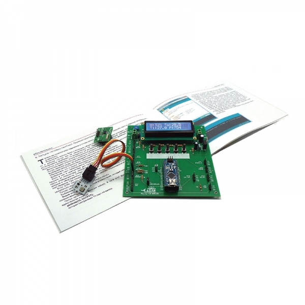
In the first two reviews ( 1 , 2 ), we introduced you to the composition and main features of the NR05 Digital Lab Kit from the Alphabet of the Electronic Engineer series.
We have repeatedly said that the possibilities of recruitment are not limited to the experiences and projects that comprise the training manual. The possibilities of recruitment are much wider!
')
Consider how you can implement control of executive devices from your smartphone or tablet using the Digital Laboratory.
The connection between the smartphone and the Arduino module installed on the expansion card will be carried out using Bluetooth technology. Of course, this will limit the possibility of wireless control of a distance of about 10 meters, but at home, often more is not required. Based on this technology, simple robots or home automation devices can be successfully controlled, and a telephone or a smartphone will serve as a free universal control panel, which can easily be reprogrammed to best solve the problem.
There are several projects on the Internet that allow you to connect Arduino with a phone via Bluetooth, and such projects will certainly help to master the principle of such a connection, but their main drawback is the inability to adapt the control program functionality and its appearance to the specific needs of the user.
We will take the path slightly more complicated, but more universal - we will write programs for the phone and for Arduino on our own. This will help you understand the principle of writing such applications and use it in your own designs.
To begin, let us explain the principle on which the link is based, which we will use. As you know, when the Arduino module is connected to a computer, a virtual serial port is configured on the computer — the COM port. It is used to fill the sketches in Arduino, as well as for the exchange of information between the computer and the Arduino microcontroller. Also on the Arduino board there are two contacts combined with pins D1 and D0 and denoted by RX and TX - respectively, the Receive and the Transmit of the standard UART interface.
By connecting a Bluetooth-UART adapter to these contacts (the HC-05 module is at our disposal, it is not included in the kit) we will receive a hardware communication channel between the device connected via Bluetooth to the adapter and Arduino.
Thus, by writing information from one device to the serial port and reading it from another (this can be done in two directions), we can organize the exchange of information between devices. The speed of such an exchange between Arduino and the smartphone in the case of the use of the module HC-05 will be 57600 baud.
For clarity, we use the RGB-LED and the servo as the actuators - both are controlled by PWM signals.
Here is the wiring diagram of the project components:

To control the actuators, we will transmit a letter from the smartphone that determines which element the command is intended for and the number that corresponds to the command parameter. The parameter can be a digit that determines whether it is necessary to enable or disable an actuator, or a digit that defines the PWM parameter.
We give the text of the program for Arduino. The program accepts data from the Bluetooth adapter, decrypts it and performs the necessary actions: turns the LED on or off, adjusts its brightness or the angle of rotation of the servo shaft.
The text is supplied with a sufficient number of comments to understand the logic of the program:
Now let's do a program for the smartphone, which should send a command with a parameter. We will use the MIT App Inventor project features for this.
The MIT App Inventor is a programming environment developed at the Massachusetts Institute of Technology (MIT). It serves to develop applications for mobile devices (smartphones and tablet computers) running on the Android operating system.
This is not really a programming language in the conventional sense; when using it, it is not necessary to write textual code in the form of lines. The program is formed in the form of blocks shown on the screen, which are simply dragged and folded like puzzles. If the blocks fit together according to the logic of the program, they “stick together”; if they do not fit, then they cannot be joined. Initially, this programming method was developed for teaching schoolchildren, so it is quite simple to learn. Of course, as in every language it has its own subtleties and techniques, but the site has enough information and examples for mastering the language. Many programs are posted on the site in the public domain.
In order to use the App Inventor programming environment, available at ai2.appinventor.mit.edu, you must have a Google account with which you authorize on the project website. Creating a program is made in any browser. The computer running this browser must be constantly connected to the Internet. The smartphone or tablet on which the program created using App Inventor will be installed must have Android OS version 4.0 or higher.
In the browser, you create the design (appearance) and the logic of the program in the form of blocks, in the same place the finished project is compiled into an executable file with the apk extension. This file can be downloaded and run on a mobile device in several ways. Perhaps the most convenient of these methods is to install the MIT AI2 Companion application on the mobile device (it is in the Play Market). App Inventor generates a QR code containing a link to the application you created, and AI2 Companion reads and installs (or updates) it. You can even draw and load your icon to launch your application. Thus, App Inventor allows you to create quite workable and visual applications for Android. Let their code is not optimal, but the convenience, simplicity and speed of creating such applications in many cases completely compensate for this drawback.
The application that works in our project is uploaded to the MIT AI2 Appiventor gallery under the name BToothHC05.
The application allows you to find a Bluetooth device, connect to it, it forms commands with parameters and sends them to the connected device, reads data from the device and displays the number of the button pressed on the expansion card.
The screen design looks like this:

There are elements (green squares, symbolizing the inserted images) that do not carry functionality, but serve as separators to improve the appearance.
If you have visited the AppInventor website and are in the programming environment in Designer mode, then when you right-click on the corresponding design element, you will see its properties on the right. Turning to Blocks mode, you can see all the blocks of the developed application.
Almost all of the blocks are essentially event handlers: pressing a button on the touchscreen, shifting the slider's slider, triggering a timer, changing the tilt of the phone (yes, almost all mobile device sensors can be used in App Inventor!).
Consider the functionality of each block.

In this block, when you press the Connect / Disconnect screen button (Button4Connect.Click event), the Bluetooth device disconnects (call BluetoothClient1.Disconnect) if it is already connected (BluetoothClient1.IsConnected), changes the text on the button to “Disconnected” and its color to gray, or calling the list of possible devices for connection (ListPicker1.Open) if there is no connection. As you can see, the block is quite readable from the point of view of even a novice programmer!

In these three blocks (from top to bottom):
- assign a global variable (all blocks will “see” it) switch1 to switch operating modes: slider or tilt;
- when you call up the list of ListPicker1 devices for connection, we need to display their addresses and names;
- when selecting a device from the ListPicker1 list, connect to it, change the color of the button and display the text Connected to DeviceName. The DeviceName is formed from a long character sequence; 8 characters starting from the 18th.

The three blocks depicted above send the symbols “P5”, “P9” and “P6” through the established connection, which should turn on or off the red, green or blue color of the LED, respectively.

When the Slider1 slider, which controls the brightness of the red LED, is shifted, this block sends an “S” symbol and numbers corresponding to the position of the slider.

When Slider2, which controls the servo, is shifted, if the corresponding mode is on (switch1 = 0), we send the character M and the position of the slider.

If the tilt sensor mode of operation is enabled, the block sends M and a tilt angle of + 90 degrees to control the servo drive.

This block switches the operating modes of the servo drive from the slider or tilt sensor and accordingly changes the inscription on the button (Text) and its color (BackgroundColor).

These two blocks are triggered by a timer event. The first block (Clock1) every 0.1 seconds (this interval is set in the properties of Clock1 timer) checks for the presence of data on whether the button was pressed on the expansion card. If the button was pressed, then for 1 second (the second block - Clock2) information about the number of the pressed button is displayed on the smartphone screen.
Now let's take a look at the video of how the LED and the servo drive from the smartphone are actually controlled in accordance with our programs.
In the same way, a sufficiently large number of actuators connected to the Arduino can be controlled. This does not require any tremendous work by the programmer when using AppInventor, and the programming of Arduino is quite simple and intuitive. You can easily add or remove unnecessary program blocks and get the functionality you need.
As can be seen from this material, an expansion board from the Digital Laboratory set allows using the Arduino add-on modules quite comfortably and visually.
Application.
Getting started in the MIT AppInventor programming environment.
As we have already written, you need a Google account to work in the AppInventor project. If you have a smartphone on Android, then you most likely already have such an account. If not, you can get it by accessing Google on the following link .
Next, go to the AppInventor website and click the Create Apps! Link, which is located in the upper right corner of the main page of the site, go to the programming environment website.
As an illustration, below is a link to a small video demonstrating the creation of a simple program that displays text when you click on a button formed on the touchscreen of a smartphone.
We have repeatedly said that the possibilities of recruitment are not limited to the experiences and projects that comprise the training manual. The possibilities of recruitment are much wider!
')
Consider how you can implement control of executive devices from your smartphone or tablet using the Digital Laboratory.
The connection between the smartphone and the Arduino module installed on the expansion card will be carried out using Bluetooth technology. Of course, this will limit the possibility of wireless control of a distance of about 10 meters, but at home, often more is not required. Based on this technology, simple robots or home automation devices can be successfully controlled, and a telephone or a smartphone will serve as a free universal control panel, which can easily be reprogrammed to best solve the problem.
There are several projects on the Internet that allow you to connect Arduino with a phone via Bluetooth, and such projects will certainly help to master the principle of such a connection, but their main drawback is the inability to adapt the control program functionality and its appearance to the specific needs of the user.
We will take the path slightly more complicated, but more universal - we will write programs for the phone and for Arduino on our own. This will help you understand the principle of writing such applications and use it in your own designs.
To begin, let us explain the principle on which the link is based, which we will use. As you know, when the Arduino module is connected to a computer, a virtual serial port is configured on the computer — the COM port. It is used to fill the sketches in Arduino, as well as for the exchange of information between the computer and the Arduino microcontroller. Also on the Arduino board there are two contacts combined with pins D1 and D0 and denoted by RX and TX - respectively, the Receive and the Transmit of the standard UART interface.
By connecting a Bluetooth-UART adapter to these contacts (the HC-05 module is at our disposal, it is not included in the kit) we will receive a hardware communication channel between the device connected via Bluetooth to the adapter and Arduino.
Thus, by writing information from one device to the serial port and reading it from another (this can be done in two directions), we can organize the exchange of information between devices. The speed of such an exchange between Arduino and the smartphone in the case of the use of the module HC-05 will be 57600 baud.
For clarity, we use the RGB-LED and the servo as the actuators - both are controlled by PWM signals.
Here is the wiring diagram of the project components:
To control the actuators, we will transmit a letter from the smartphone that determines which element the command is intended for and the number that corresponds to the command parameter. The parameter can be a digit that determines whether it is necessary to enable or disable an actuator, or a digit that defines the PWM parameter.
We give the text of the program for Arduino. The program accepts data from the Bluetooth adapter, decrypts it and performs the necessary actions: turns the LED on or off, adjusts its brightness or the angle of rotation of the servo shaft.
The text is supplied with a sufficient number of comments to understand the logic of the program:
Spoiler
// connect the libraries of the servo and LCD-indicator
#include <Servo.h>
#include <LiquidCrystal.h>
// set 5 values to determine the number of the pressed button
// in the get_key function
#define NUM_KEYS 5
int adcKeyVal [NUM_KEYS] = {30, 150, 360, 535, 760};
// create an instance of the LCD indicator object
LiquidCrystal lcd (A1, A2, A3, 2, 4, 7);
// create an instance of the servo object
Servo servo;
int btValue; // variable to store the data received from the BT adapter
char command; // command coming from the COM port
void setup () {
// open the bluetooth COM port, clear it, set the timeout
Serial.begin (57600);
Serial.flush ();
Serial.setTimeout (4);
// initialize the LCD (16 characters, 2 lines)
lcd.begin (16, 2);
lcd.clear ();
lcd.print ("Master Kit-READY");
delay (2000);
lcd.clear ();
// assign the 3rd digital pin to the servo
servo.attach (3);
pinMode (5, OUTPUT);
pinMode (6, OUTPUT);
pinMode (9, OUTPUT);
digitalWrite (5, LOW);
digitalWrite (6, LOW);
digitalWrite (9, LOW);
}
void loop () {
int key = get_key (); // check if the button is pressed on the board and determine its number
// if the button is pressed, send its number to the COM port
// this number will be read by the smartphone
if (key> 0) {
Serial.print (key);
delay (500);
}
// if there is data that came via bluetooth, remember them
if (Serial.available ()> 0) {
// read the first byte from the port (command)
command = Serial.read ();
// read the numbers from the port (command parameter)
btValue = Serial.parseInt ();
// display data received via bluetooth on LCD
lcd.setCursor (0,0);
lcd.print (command);
lcd.print ('');
lcd.print (btValue);
lcd.print ("");
delay (10);
switch (command) {
case 'P': // if the P command is received, then switch the colors of the LED
pinSwitch (btValue);
break;
case 'S': // S - slider 1 (PWM red color)
pwm5 (btValue);
break;
case 'M': // M - slider 2 (PWM servo)
servo3 (btValue);
break;
}
}
}
// function changes the state of the digital pin to the opposite
void pinSwitch (int pin) {
digitalWrite (Pin,! digitalRead (Pin));
}
// function changes the PWM on pin 5 (the red color of the LED)
void pwm5 (int pwmValue) {
analogWrite (5, pwmValue);
}
// function changes the PWM on pin 3
void servo3 (int angleValue) {
int angle = map (angleValue, 0, 180, 5, 180);
servo.write (angle);
}
// function returns the number of the pressed button on the board
int get_key ()
{
int input = analogRead (A6);
int k;
for (k = 0; k <NUM_KEYS; k ++)
if (input <adcKeyVal [k])
return k + 1;
return 0;
}
Now let's do a program for the smartphone, which should send a command with a parameter. We will use the MIT App Inventor project features for this.
The MIT App Inventor is a programming environment developed at the Massachusetts Institute of Technology (MIT). It serves to develop applications for mobile devices (smartphones and tablet computers) running on the Android operating system.
This is not really a programming language in the conventional sense; when using it, it is not necessary to write textual code in the form of lines. The program is formed in the form of blocks shown on the screen, which are simply dragged and folded like puzzles. If the blocks fit together according to the logic of the program, they “stick together”; if they do not fit, then they cannot be joined. Initially, this programming method was developed for teaching schoolchildren, so it is quite simple to learn. Of course, as in every language it has its own subtleties and techniques, but the site has enough information and examples for mastering the language. Many programs are posted on the site in the public domain.
In order to use the App Inventor programming environment, available at ai2.appinventor.mit.edu, you must have a Google account with which you authorize on the project website. Creating a program is made in any browser. The computer running this browser must be constantly connected to the Internet. The smartphone or tablet on which the program created using App Inventor will be installed must have Android OS version 4.0 or higher.
In the browser, you create the design (appearance) and the logic of the program in the form of blocks, in the same place the finished project is compiled into an executable file with the apk extension. This file can be downloaded and run on a mobile device in several ways. Perhaps the most convenient of these methods is to install the MIT AI2 Companion application on the mobile device (it is in the Play Market). App Inventor generates a QR code containing a link to the application you created, and AI2 Companion reads and installs (or updates) it. You can even draw and load your icon to launch your application. Thus, App Inventor allows you to create quite workable and visual applications for Android. Let their code is not optimal, but the convenience, simplicity and speed of creating such applications in many cases completely compensate for this drawback.
The application that works in our project is uploaded to the MIT AI2 Appiventor gallery under the name BToothHC05.
The application allows you to find a Bluetooth device, connect to it, it forms commands with parameters and sends them to the connected device, reads data from the device and displays the number of the button pressed on the expansion card.
The screen design looks like this:
There are elements (green squares, symbolizing the inserted images) that do not carry functionality, but serve as separators to improve the appearance.
If you have visited the AppInventor website and are in the programming environment in Designer mode, then when you right-click on the corresponding design element, you will see its properties on the right. Turning to Blocks mode, you can see all the blocks of the developed application.
Almost all of the blocks are essentially event handlers: pressing a button on the touchscreen, shifting the slider's slider, triggering a timer, changing the tilt of the phone (yes, almost all mobile device sensors can be used in App Inventor!).
Consider the functionality of each block.
In this block, when you press the Connect / Disconnect screen button (Button4Connect.Click event), the Bluetooth device disconnects (call BluetoothClient1.Disconnect) if it is already connected (BluetoothClient1.IsConnected), changes the text on the button to “Disconnected” and its color to gray, or calling the list of possible devices for connection (ListPicker1.Open) if there is no connection. As you can see, the block is quite readable from the point of view of even a novice programmer!
In these three blocks (from top to bottom):
- assign a global variable (all blocks will “see” it) switch1 to switch operating modes: slider or tilt;
- when you call up the list of ListPicker1 devices for connection, we need to display their addresses and names;
- when selecting a device from the ListPicker1 list, connect to it, change the color of the button and display the text Connected to DeviceName. The DeviceName is formed from a long character sequence; 8 characters starting from the 18th.
The three blocks depicted above send the symbols “P5”, “P9” and “P6” through the established connection, which should turn on or off the red, green or blue color of the LED, respectively.
When the Slider1 slider, which controls the brightness of the red LED, is shifted, this block sends an “S” symbol and numbers corresponding to the position of the slider.
When Slider2, which controls the servo, is shifted, if the corresponding mode is on (switch1 = 0), we send the character M and the position of the slider.
If the tilt sensor mode of operation is enabled, the block sends M and a tilt angle of + 90 degrees to control the servo drive.
This block switches the operating modes of the servo drive from the slider or tilt sensor and accordingly changes the inscription on the button (Text) and its color (BackgroundColor).
These two blocks are triggered by a timer event. The first block (Clock1) every 0.1 seconds (this interval is set in the properties of Clock1 timer) checks for the presence of data on whether the button was pressed on the expansion card. If the button was pressed, then for 1 second (the second block - Clock2) information about the number of the pressed button is displayed on the smartphone screen.
Now let's take a look at the video of how the LED and the servo drive from the smartphone are actually controlled in accordance with our programs.
In the same way, a sufficiently large number of actuators connected to the Arduino can be controlled. This does not require any tremendous work by the programmer when using AppInventor, and the programming of Arduino is quite simple and intuitive. You can easily add or remove unnecessary program blocks and get the functionality you need.
As can be seen from this material, an expansion board from the Digital Laboratory set allows using the Arduino add-on modules quite comfortably and visually.
Application.
Getting started in the MIT AppInventor programming environment.
As we have already written, you need a Google account to work in the AppInventor project. If you have a smartphone on Android, then you most likely already have such an account. If not, you can get it by accessing Google on the following link .
Next, go to the AppInventor website and click the Create Apps! Link, which is located in the upper right corner of the main page of the site, go to the programming environment website.
As an illustration, below is a link to a small video demonstrating the creation of a simple program that displays text when you click on a button formed on the touchscreen of a smartphone.
Source: https://habr.com/ru/post/391383/
All Articles