FLProg - combining Arduino boards into an information ring
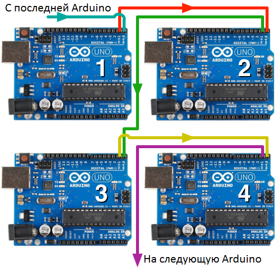
Starting from version 1.10.5, FLProg allows you to combine several Arduino boards into a ring UART network. First, consider how this happens. The boards are interconnected in accordance with the scheme shown in the title illustration. Suppose that card 1 sends through UART a data packet containing the card identifiers, variable, as well as the value of the variable. Card 2 accepts this packet and if it does not need data from this variable, then simply sends this packet further. If, in accordance with the program, the value of this variable is needed by the controller, then the value from the packet is copied into the internal variable, and the packet is also sent further along the ring.
When in this way the package, having passed the entire ring, returns to the board that sent it, the transmission of the package will stop.
Thus, the data from the package is available to any board connected to the ring, and any of the boards can also be the initiator of sending a packet.
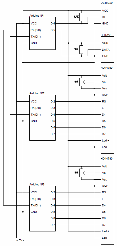
The scheme of the test stand:
')
The logic of work is as follows:
- Arduino №1 receives data on temperature and humidity c sensors.
- Arduino №2 displays the temperature from the sensor DS18B20.
- Arduino №3 displays temperature and humidity from a DHT-22 sensor.
To avoid angry comments that such logic is not needed and is nonsense, I’ll clarify that this project is purely educational and is intended to explain the principles of data transmission through the information ring. To do this, make a little more nonsense in the logic of work.
- The digital temperature value from the DS18B20 sensor catches the Arduino # 3, then converts it into a string and sends it to the ring. This line catches Arduino №2 and displays on the display.
- The digital temperature value from the DHT-22 sensor catches the Arduino # 2, then converts it into a string and sends it to the ring. This line catches Arduino number 3 and displays on the display.
- The digital humidity value from the DHT-22 sensor catches the Arduino # 3, then converts it into a string and displays it on the display.
So, let's begin.
Open the FLProg program and create a project for the Arduino # 1. We throw the OneWire bus scanner on the first board (library of elements, “Miscellaneous” folder). This block, on the leading edge at the input En, scans the OneWire bus and, when the sensors are located on them, adds the detected addresses to the associated arrays. To parameterize a block, call the block editor (double click on the block).
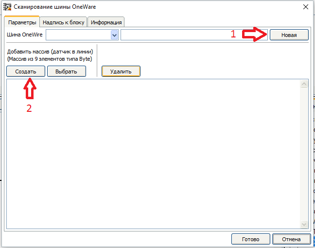
- First, create a new OneWire bus.

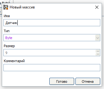
- Then create an array. Since the sensor on our bus is planned alone, we create one array.
Now we will organize the scheme of starting this block once at the start of the program. To do this, we collect such a scheme.
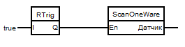
R - The trigger is located in the Triggers folder of the element library. It serves to highlight the leading edge of the pulse fed to the input. At its output there will be an impulse lasting one cycle of the program when the input level goes from low to high.
Then we create a new board and drag the DS18x2x temperature sensor (component library, “Sensors” folder) onto it. Call the block editor and parameterize the sensor.
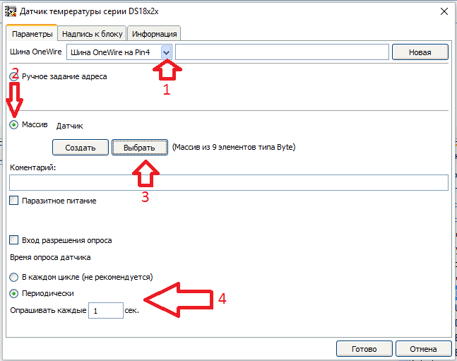
- From the drop-down list, select the previously created OneWire bus on pin 4
- Select the mode of setting the address "Array"
- Select the previously created array "Sensor"
- We set a periodic polling mode of the sensor, with a frequency of polling every 1 sec.
Now the value obtained from the sensor must be sent to the ring.
In FLProg, you can connect a controller to the ring in two ways. In this project for Arduino # 1, we will consider the first method - through the blocks of sending a variable to a ring.
Let's pull out the “Send variable to ring” block (library of elements, UART folder) on the board, and call the block editor for it.
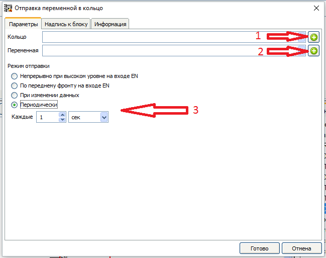
- First add the controller to the ring.
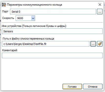
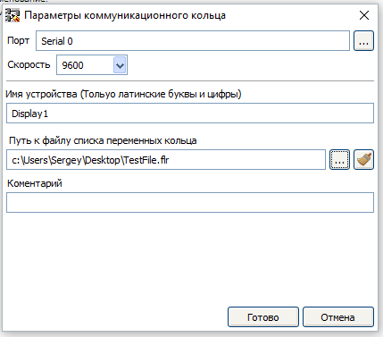
In the window that opens, you must select the port to connect to the ring, the port speed, and set the device name in the ring. Also for the convenience of working with the project, it is desirable to create a file of the list of ring variables through which all controllers participating in it will be synchronized. - Then create a variable that will be passed to the ring.
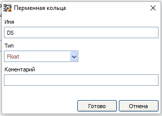
In the create variable window, you must specify the name of the variable and its type. - After that we set the periodic mode of sending a variable, with a period of 1 second.
After parameterizing the block, we connect the sensor and send blocks to each other and set the constant constant to the input En of the send block for the variable.

We create a new board and drag the DHT-22 sensor onto it (the library of elements, the “Sensors” folder). Call the block editor and parameterize the sensor.

- Choose a pin to connect the sensor
- Select the type of sensor
- Set the availability of temperature and humidity outputs
- Set the periodic method of polling the sensor with a periodicity of 1 second
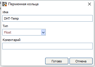
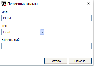
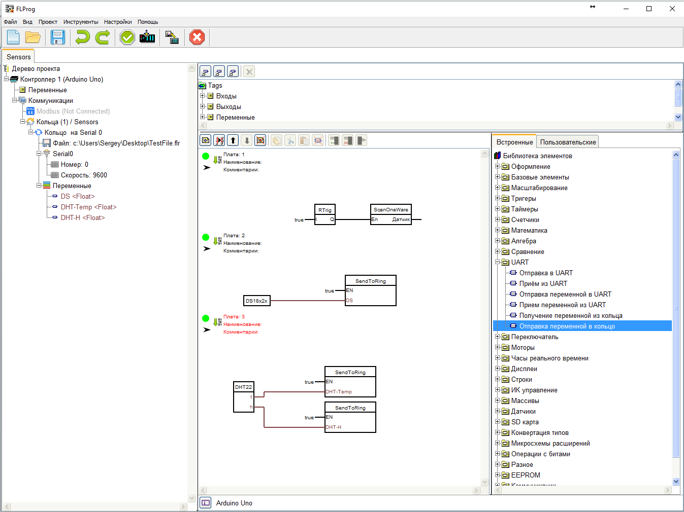
Then, drag and drop two blocks of sending a variable to the ring onto the third board, select the existing ring in the block settings, and create each variable in each of them.
Let us connect the blocks together, and set true constants on the inputs En of the sending variable blocks.
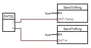
With the project for Arduino # 1 finished. You should get this scheme:
Now we are creating a new project for Arduino # 2.
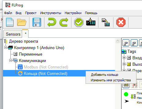
Immediately connect the board to the ring. Here we will use the second method, through the project tree. We open the tree to the “Communications” branch inclusively and right-click on the “Rings” item. In the context menu that appears, select the item "Add ring".
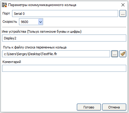
The already known window of ring parameters opens. We again need to enter the device name in the ring and select the port through which the device is connected to the ring. But now we do not create a variable ring file, but select the previously created one. This automatically synchronizes variables between projects.
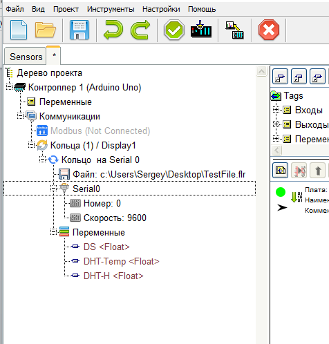
All ring parameters can be changed through the project tree by calling the context menu on the corresponding branches.
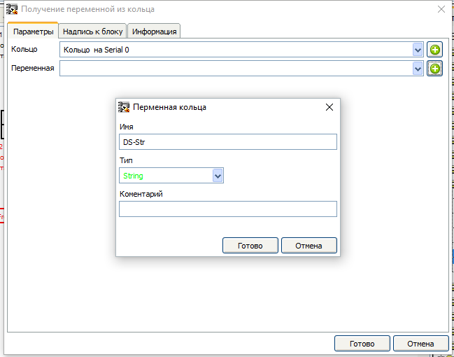
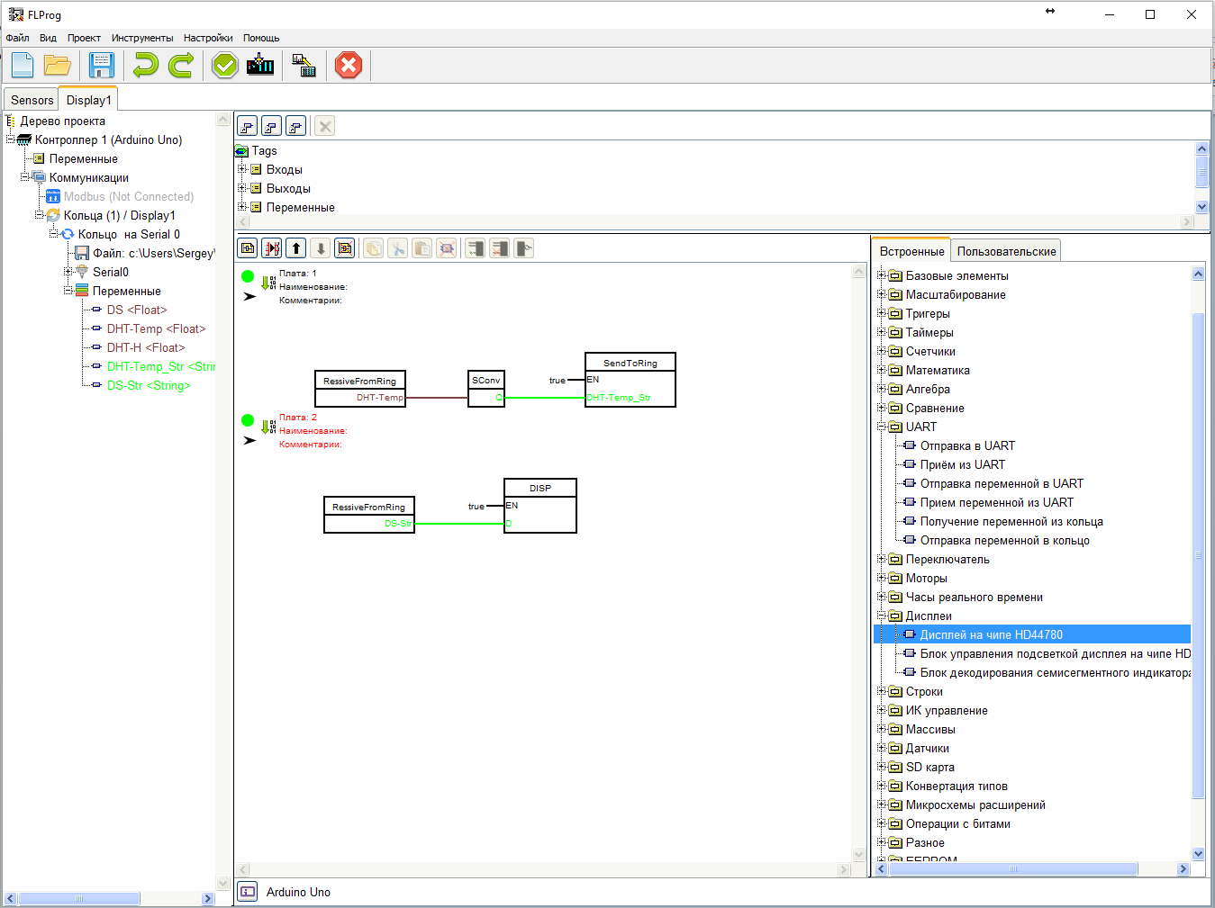
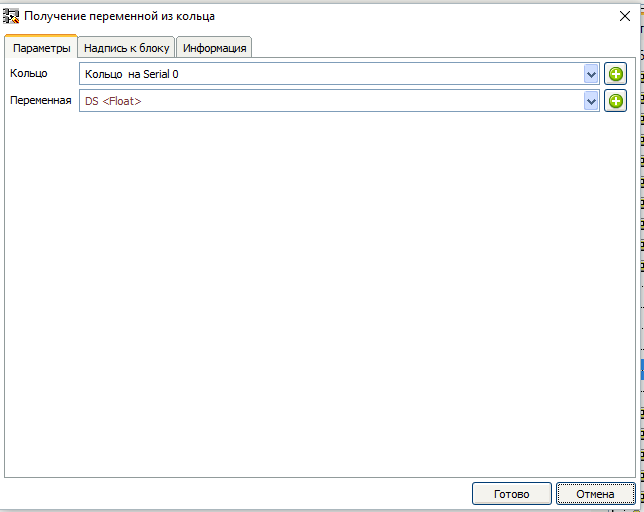
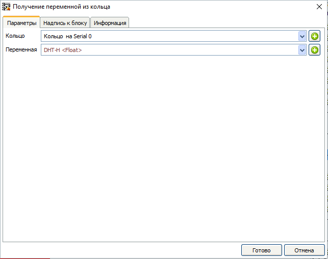
According to the algorithm, the Arduino # 2 catches a variable about the temperature from the DHT-22 sensor, turns its value into a string and sends it to a ring. To do this, drag the “Get a variable out of the ring” block (library of elements, “UART” folder) onto the schematic and call the editor for it.
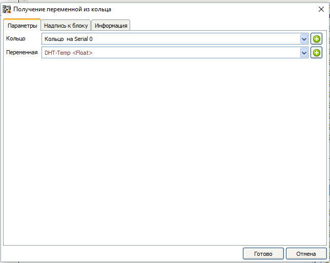
In the editor, select the ring and the corresponding variable.
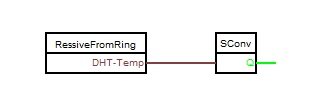
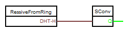
Then drag the "String conversion" block (element library, "Type Conversion" folder) to the scheme and connect the input of this block with the output of the "Get variable from ring" block
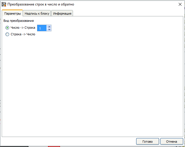
Then we call the editor for the block "String conversion".
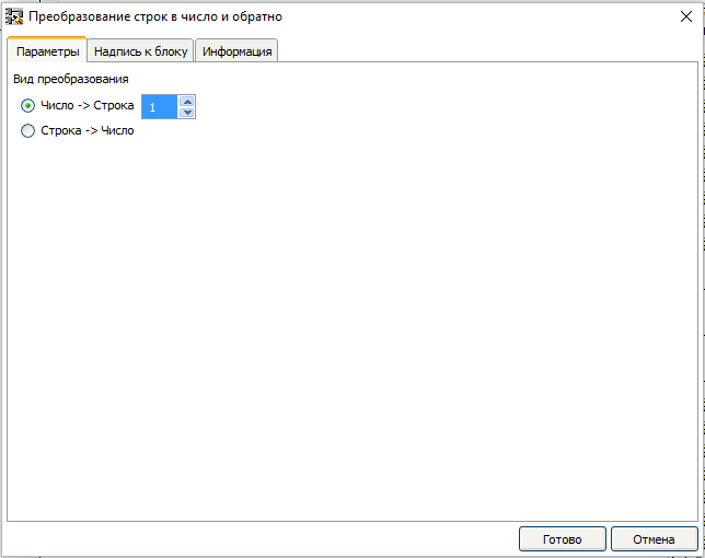
Since the input of this block is a value of type Float, we have the opportunity to set the number of decimal places when converting to a string. I think one decimal place is enough for us.
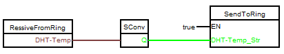
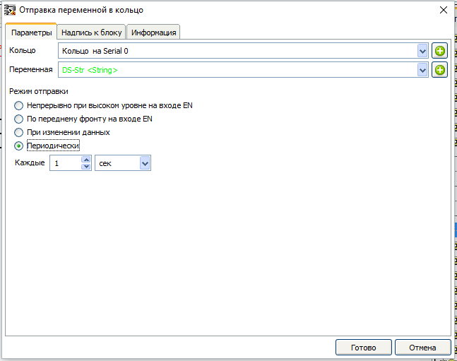
Then we pull out the block “Sending a variable to a ring” (the library of elements, UART folder) on the scheme, and using the editor, select the ring, and create a new variable that will be sent to the ring. We also set a periodic send mode, with a period of 1 sec.


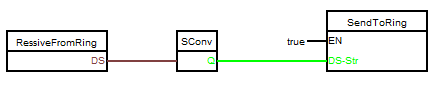
Then we connect the blocks to each other and set the constant true at the input En of the sending variable block.
Let's create a new board and drag the “Get a variable out of the ring” block onto it (library of elements, “UART” folder) and call the editor for it. In the editor, select the connected ring. Since, in accordance with the algorithm, the Arduino # 3 prepares the value for display on the display, we will create a new variable, which this controller will send to us.
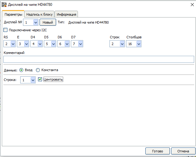
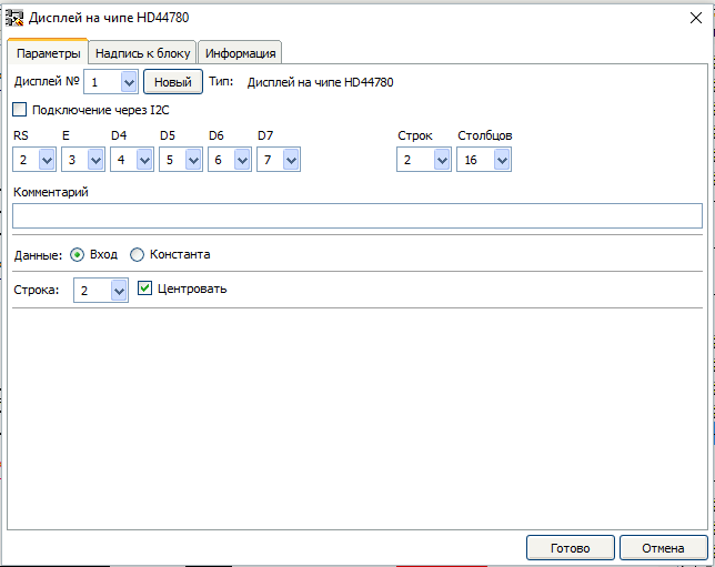
Now let's drag the “Display on HD44780 chip” block (elements library, “Displays” folder) onto the scheme, and call the editor for it and parameterize it.
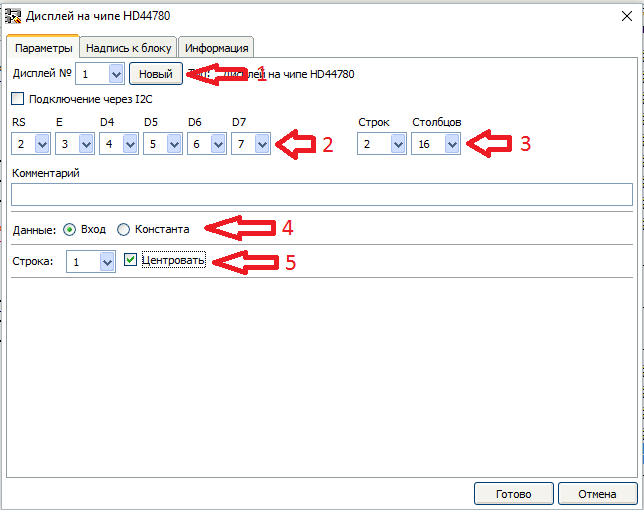
- Create a new display
- Let's set connection according to the scheme
- Set the display parameters
- Configure the display of data from the input block
- Set the display to the center of the first row.
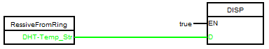
After that, we connect the blocks and set the constant true on the input En of the display block.

With the project for Arduino number 2 finished. You should get this scheme:
Create a project for Arduino # 3.
Connect the controller to the ring by any of the above methods. When connecting, select the previously created variable ring file.
According to the algorithm, the Arduino controller number 3 catches the temperature value from the DS18B20 sensor from the Arduino No. 1 and converts it into a string and sends this string to the ring for the Arduino No. 2. All the necessary variables for this we already exist. Therefore, similar to Arduino # 2. Drag and drop blocks “Getting a variable out of a ring” (element library, “UART” folder), “String conversion” blocks (element library, “Type Conversion” folder) and “Sending variable to ring” block (element library, UART folder) onto the schema. Then we parameterize them.
"Getting a variable from the ring"
"String Conversion"

"Sending a variable to the ring"
After that we collect them in the scheme
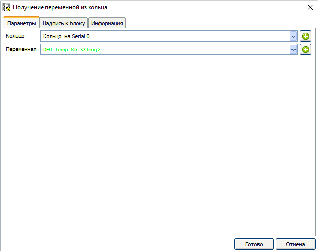
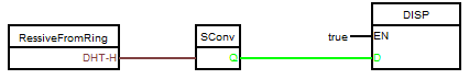
Create a new board to display the temperature from the DHT-22 sensor. Similarly, Arduino # 2 is dragged "Getting a variable out of the ring" (library of elements, folder "UART") and "Display on an HD44780 chip" (library of elements, folder "Displays"). We parameterize them.
"Getting a variable from the ring"
"Display on the HD44780 chip"
We connect with each other.
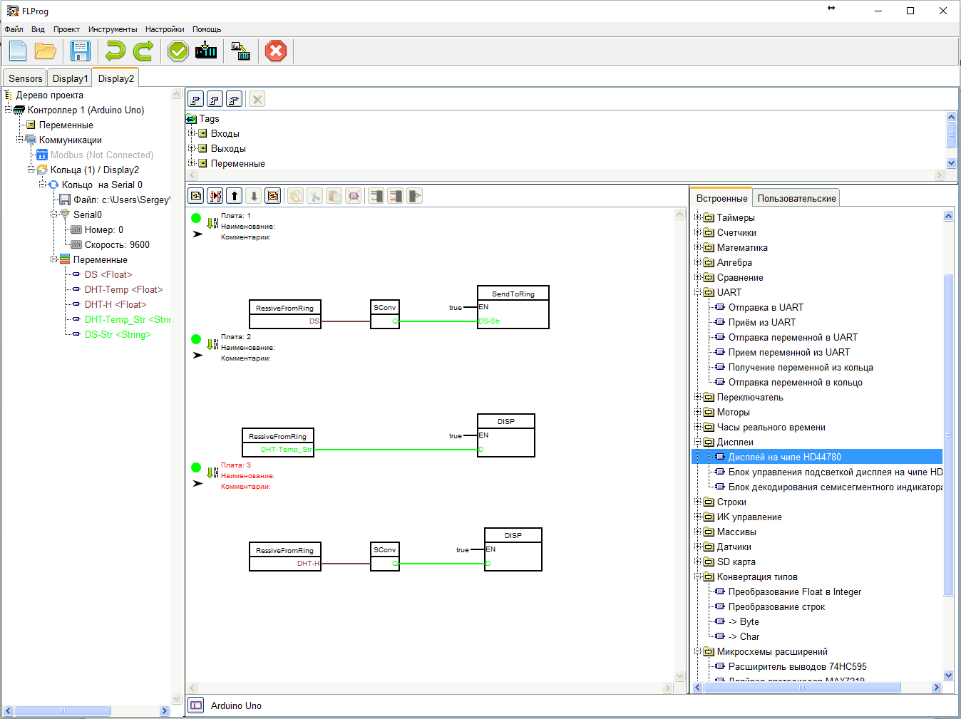
Create a new board to display humidity.
We also drag and drop the “Getting a variable out of the ring” block (library of elements, “UART” folder) onto the board and parameterize it.
Then we drag the "String conversion" block (library of elements, the "Type Conversion" folder), connect it with the "Get the variable from the ring" block and parameterize it.
Well and in the last turn we drag the block “Display on the HD44780 chip” (library of elements, folder “Displays”). When the unit is parameterized, we select an already existing display and output the moisture value in the center of the second line.
We connect the blocks together.
Creating a program for Arduino number 3 is completed.
Final result.
Thanks for attention.
Source: https://habr.com/ru/post/391365/
All Articles