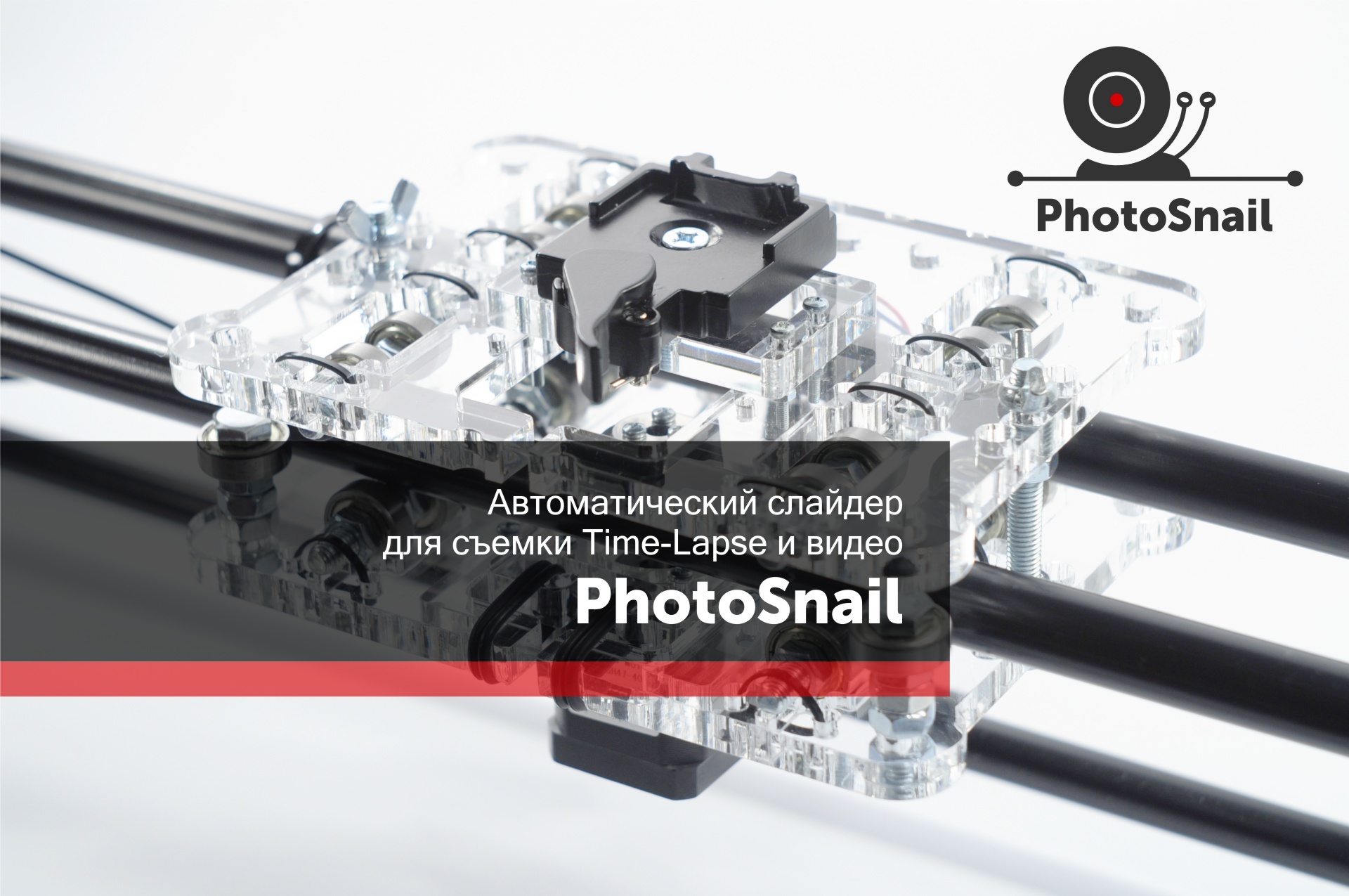
DIY motorized slider for shooting TimeLapse and video
Hello!
I got a working version of the PhotoSnail slider, which I wanted to share.
What is PHOTOSNAIL?
PhotoSnail is an open project of the automated moving camera system (Slider) with automatic tracking of objects for photo and video. There is also an idea to use it to create an incomplete Photo 360 .
The control unit of the system is based on Arduino and the same as in the open source project PhotoPizza
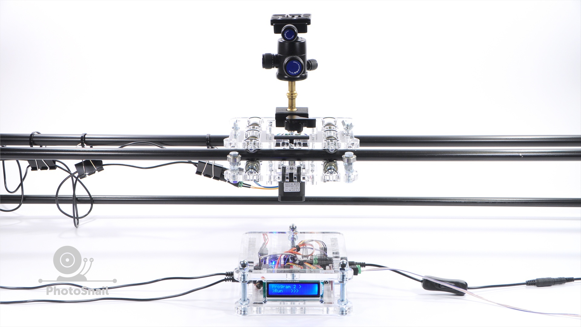
PhotoSnail is under development and now only the platform is moved along guides with adjustable parameters. In the program settings, you can set the total length of movement of the camera, the number of frames, direction, acceleration and pause for shooting. The camera is connected to the control unit via a sync cable and any camera model that has a connector for connecting a wired remote controller is supported.
')
EXAMPLE VIDEO CAMERA MOVEMENT
TIME-LAPSE PHOTO EXAMPLE WITH CAMERA MOVEMENT
Examples created using similar sweets.
Own examples will publish in the update to this article.
BASIC PROJECT IDEAS
LOW COST - my goal was to create a truly affordable solution that would be affordable for many amateur photographers and businesses of all sizes. As a result, the cumulative cost of all elements is significantly lower than any analogues comparable in characteristics.
ACCESSIBILITY OF COMPONENTS - I specifically selected components so that you do not have any significant problems with their search and purchase. For example, the project uses bearings from roller skates, which you can find in the nearest sports store.

EASY ASSEMBLY - the assembly of the structure does not take much of your time and does not require special knowledge or tools.
The electronics of the control unit is assembled without using a soldering iron.
UNIVERSALITY - I try to create equipment, elements of which can be used to solve additional problems.
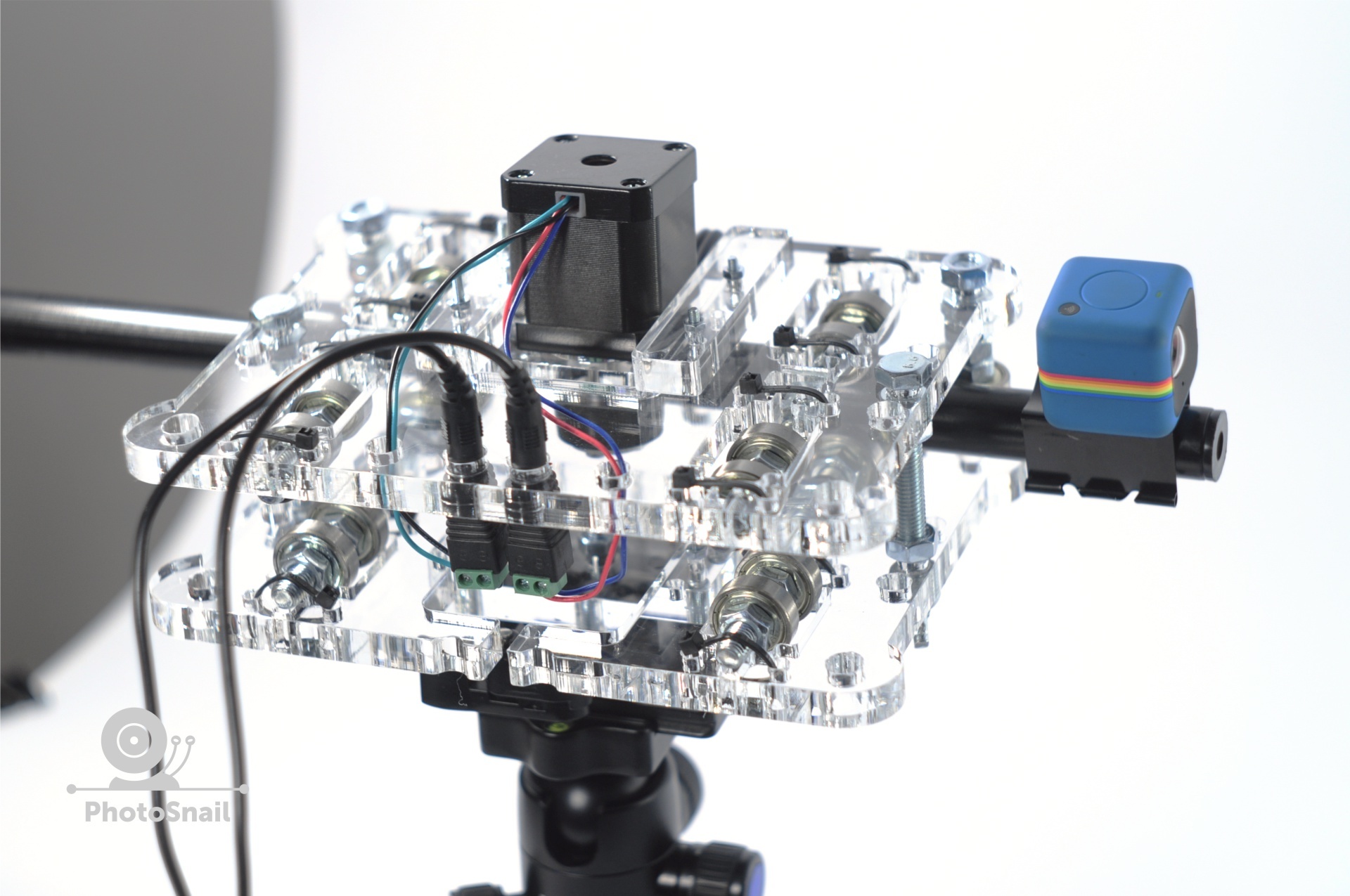
For example, the slider can be used as a drive for the movement of the rod, at the end of which the action camera is fixed.
This method of movement can be used to solve creative problems. Create a camera flight through obstacles with the effect of Time-lapse or just shooting video.

The slider is not limited to the drive belt and can move over long distances.
As guides, I use the IKEA cornice, for fixing the guides from there the same kit for fastening the cornice.
The eaves can dock to increase the length of movement of the slider.
Slider can be used for stacking.
To increase the depth of field photos in macro.
Several frames of the subject are made at different distances and then these frames are stitched into one photo.
In the process of developing a new mount for the guides.
Will support round and square in section guides, attachment to the tripods.


DESIGN
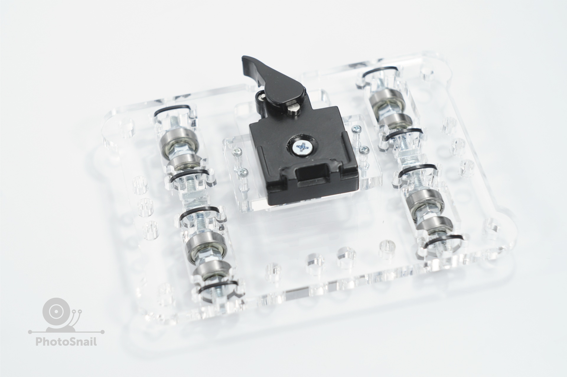
The slider consists of two platforms, which are tightened and clamp the guides between themselves, relying on the pressure rollers.
Thus, the slider itself aligns the guides parallel to each other.
Guides can be hung to trees, tripods and they will be located in parallel.
The platform can move upside down and sideways, while keeping the camera normally.

At the bottom there are two connectors for connecting the engine to the control unit.

The drive roller is pressed against one of the guides, slippage during horizontal movement and small angles is not observed.
It is also possible to put a toothed roller on the motor shaft and use the drive belt to move the platform at large angles of the guides, also at 90 degrees.

A tripod head or camera mount is attached to the upper platform.

CONTROL
Menu map of the control unit

Description of the functions of the control unit
The control unit has 4 customizable programs with the same set of parameters. Programs can be configured for different shooting conditions. For example, if you are shooting a video, you need to configure the program to quickly move the site. For shooting TimeLapse, you need to configure a long pause and the number of frames, etc.
Value of parameters
Run - run the program
steps - sets the total distance that the camera should travel
If the value is “0”, the infinite mode of movement inf is activated
speed - movement speed
frame - the number of frames per total distance of camera movement, specified in the steps parameter
pause - delay after the relay is triggered (camera shutter). Installed in accordance with the shutter speed of the camera (value in milliseconds)
If the value is pause - none, the interval shooting mode is activated without stopping the camera.
accel - acceleration after the start of the program, a smooth start and stop the camera
dir - the direction of movement, also changes the button on the remote

The meaning of the buttons on the remote
In standby
Navigation in the menu is done using the arrow buttons.
A program is selected to the right and left, from 1 to 4 . Each program has its own settings.
Use the up and down buttons to select the option to edit.
To start the program or to edit a parameter, press the “OK” button. Same button to save the edited parameter.
To enter a new value, select the parameter and press the buttons with numbers, the up and down buttons change the values step by step or give the opportunity to choose a value from several options.
The "#" button resets the value to "0"
Button "*" changes direction in "Run" mode
In the program mode
The up and down arrow buttons change the speed of the camera movement step by step.
The “OK” button stops the program (camera movement)
LASER CUTTING FILES
DOWNLOAD
The material can use plywood with a thickness of 10 mm.
For example, you can look at the turntable PhotoPizza D340 Wood

FILES FOR ARDUINO FIRMWARE
DOWNLOAD
The firmware is used the same as in the project PhotoPizza.
LIST OF COMPONENTS
SLIDER COMPONENTS
CONTROL UNIT AND MOTOR COMPONENTS
EXTERNAL BATTERY FOR AUTONOMOUS POWER SUPPLY
The control unit is powered by 12 volts
UPDATE PROJECT
03.03.2016
Made minor changes to the drawings.
Changed the part for mounting the tripod head, adapted it for large installation.
In connection with this, the details of the upper and lower areas have changed.
On the upper platform added holes for mounting the engine.
The illustration below shows the old parts, old in comparison with new and new ones.

New files called PhotoSnail2
Source: https://habr.com/ru/post/391209/
All Articles