Laboratory microwave. Untold in datasheets for MAAP amplifiers
In the past, the user requirements for the operational documentation for the element base were described in a superficial way, some omissions of the manufacturer of the HMC996 microcircuit chipset Hittite Microwave corp. In this text I will try to highlight the serious problem of the MAAP-010168 chip from the manufacturer MACOM TS.

The identification of this problem took place in the run-up to the docking tests of the product. At first, we mostly sinned on the construction of our project. The atmosphere was permeated with despair. Began to check the most crazy ideas, fantastic hypotheses. The next goodbyes to families, night engineering, fast food, coffee and other "delights" were planned. After multiple attempts to reshape the configuration, we seriously thought about the possibility of a manufacturing defect for MACOM. They took a chip from another party - the same nonsense. Created the thought of a constructive marriage of the chip.
')
Call to the representation of the company. Politely answered, but made it clear that they are not able to help us, they can only send a request to the developers. The operator thought for a while: “Although, we had a similar request a few months ago. The problem is very similar to yours. ” We received contacts of unknown colleagues. The comrades from Radioservice (special thanks for the assistance provided to Valery Pavlovich Popov) by telephone described their experience with the microcircuit and suggested a solution. The answer, as it turned out, was naively simple.
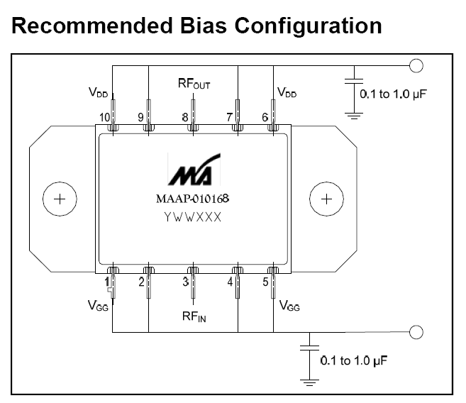
The MAAP-010168 amplifier was necessary for us to build up a pulsed (pulse frequency 1 KHz, duty cycle 0.3%) power in the L-band. This is what the recommended amplifier circuit looks like:
I note that in dtsh (datasheet) no reservations about the power supply mode are made. We turn on the IC with gates (voltage pulses Vdd), feed power synchronously with the gates to the input and observe the spectrum of the signal at the output.
The following problem is observed: Excitation of the chip at low frequencies (about 150 KHz) .
At the stage of prototyping (the image in the top of this publication) this shameful ailment was missed, and in the piece of iron, when the oscillograms floated, the volume of trouble became obvious. Returned to the layout - there is the same nonsense. As a result, the model was raped by all means available to engineers (you can again see the result in the photo), but to no avail.
The strobe signal directly on the pin IC looked as follows:
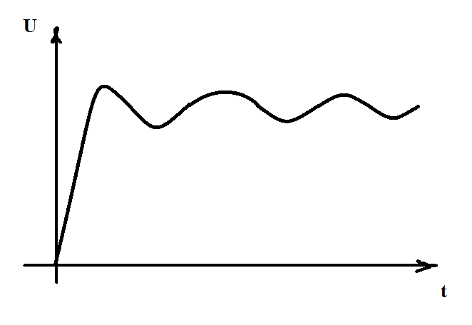
The power beats led, of course, to modulations. In the spectrum of the signal is garbage, which leaves part of the useful energy.
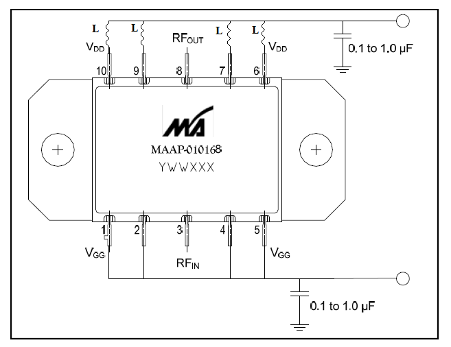
The documentation did not contain even a small description of the internal structure of the IC. Colleagues from "Radioservice" found out that the stuffing contains 4 amps! For each its own power leg (we also thought that the number of conclusions due to the current load on the line). Accordingly, when managing them, it is necessary to take into account the mutual influence. Better yet, by all available means, this mutual influence is damped. That modernized the circuit to the following:
The inductance rating, of course, must be carefully selected based on the strobe parameters, circuit configuration, even the design. You can use the EMC chokes, there is already more dimensional factor and current play a role. The solution is quite simple and, as it seems now, the obvious.
The identification of this problem took place in the run-up to the docking tests of the product. At first, we mostly sinned on the construction of our project. The atmosphere was permeated with despair. Began to check the most crazy ideas, fantastic hypotheses. The next goodbyes to families, night engineering, fast food, coffee and other "delights" were planned. After multiple attempts to reshape the configuration, we seriously thought about the possibility of a manufacturing defect for MACOM. They took a chip from another party - the same nonsense. Created the thought of a constructive marriage of the chip.
')
Call to the representation of the company. Politely answered, but made it clear that they are not able to help us, they can only send a request to the developers. The operator thought for a while: “Although, we had a similar request a few months ago. The problem is very similar to yours. ” We received contacts of unknown colleagues. The comrades from Radioservice (special thanks for the assistance provided to Valery Pavlovich Popov) by telephone described their experience with the microcircuit and suggested a solution. The answer, as it turned out, was naively simple.
The MAAP-010168 amplifier was necessary for us to build up a pulsed (pulse frequency 1 KHz, duty cycle 0.3%) power in the L-band. This is what the recommended amplifier circuit looks like:
I note that in dtsh (datasheet) no reservations about the power supply mode are made. We turn on the IC with gates (voltage pulses Vdd), feed power synchronously with the gates to the input and observe the spectrum of the signal at the output.
The following problem is observed: Excitation of the chip at low frequencies (about 150 KHz) .
At the stage of prototyping (the image in the top of this publication) this shameful ailment was missed, and in the piece of iron, when the oscillograms floated, the volume of trouble became obvious. Returned to the layout - there is the same nonsense. As a result, the model was raped by all means available to engineers (you can again see the result in the photo), but to no avail.
The strobe signal directly on the pin IC looked as follows:
The power beats led, of course, to modulations. In the spectrum of the signal is garbage, which leaves part of the useful energy.
The documentation did not contain even a small description of the internal structure of the IC. Colleagues from "Radioservice" found out that the stuffing contains 4 amps! For each its own power leg (we also thought that the number of conclusions due to the current load on the line). Accordingly, when managing them, it is necessary to take into account the mutual influence. Better yet, by all available means, this mutual influence is damped. That modernized the circuit to the following:
The inductance rating, of course, must be carefully selected based on the strobe parameters, circuit configuration, even the design. You can use the EMC chokes, there is already more dimensional factor and current play a role. The solution is quite simple and, as it seems now, the obvious.
Source: https://habr.com/ru/post/391197/
All Articles