Thinking out loud. Four is better than one ... Or the concept of a transport quadrocopter
The article highlights the fundamental flaws of an aircraft such as a helicopter, and suggests their solution. The possible application of this concept in robotic systems and complexes is considered. The described approach does not pretend to unambiguity and accuracy, and the article aims to share a technical idea with the readers of GT.
An aircraft (LA) is a machine or device for flying in the atmosphere or outer space. At the moment, the classification of the aircraft has a huge variety of types and types of aircraft; among this set, one of the actively used types of aircraft can be identified - the helicopter.
')
Let us single out the principal shortcomings of the helicopter as a class:

Figure 1 - Mi-26 helicopter in three projections
The helicopter's cargo cabin is 320 cm wide; by comparison, the BTR-70 armored personnel carrier is 280 cm wide, and there is a space of 20 cm between each side of the conveyor and the wall of the helicopter cargo compartment, which is a negative factor when loading equipment of such dimensions (Fig. 2, on right). Figure 2 (left) illustrates the complexity of the loading process using a forklift.
The presence of this factor brings inconvenience in the use of helicopters in civilian cargo transportation and is critical when using such aircraft in emergency situations and military operations.


Figure 2 - Process of loading with a forklift (left), loading of the BTR-70 (right)
A quadcopter is an aircraft with four rotors rotated diagonally in opposite directions. This arrangement of rotors allows aircraft with a fuselage wider than in helicopters (Fig. 3), and the presence of four rotors will provide four swept zones, which will allow landing and take-off during side roll.
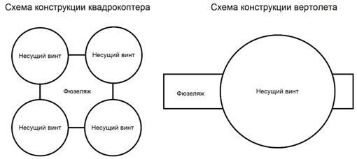
Figure 3 - Block diagram of quadcopter and helicopter designs
When using this scheme, such nodes as the fuel system, control system, radar system, electrician are placed in the upper part of the fuselage in a special armored capsule (Fig. 4). This layout allows you to place the cargo compartment hatches and cargo ladders in any of the 5 sides of the fuselage (Fig. 5): from four sides and bottom (vertical loading hatch).
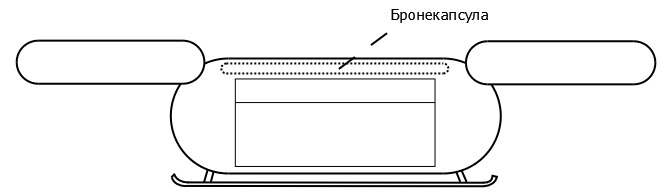
Figure 4 - Location of the broncapsule

Figure 5 - Placement of cargo hatches
The considered approach has the following disadvantages:
Possible solutions:

Figure 7 - Placement of rotors
APPLICATION OF THE CONCEPT IN THE ROBOTICS
Unmanned aerial vehicle (UAV) - an aircraft without crew on board, implemented using robotics. The implementation of a cargo quadcopter, like a UAV, is expedient:
Centralized management with a human operator (“one to one” relationship ). The structure of the control system:
Centralized control with a control tower (one-to-many communication). Management System Structure:
Decentralized management (many-to-many relationship). Management System Structure:
FORMULATION OF THE PROBLEM
An aircraft (LA) is a machine or device for flying in the atmosphere or outer space. At the moment, the classification of the aircraft has a huge variety of types and types of aircraft; among this set, one of the actively used types of aircraft can be identified - the helicopter.
')
Let us single out the principal shortcomings of the helicopter as a class:
- the complexity of loading cargo and equipment of large dimensions due to the narrow cargo compartment,
- Landing is possible only in the absence of lateral roll due to the narrow fuselage and one zone swept by the rotor.
Figure 1 - Mi-26 helicopter in three projections
The helicopter's cargo cabin is 320 cm wide; by comparison, the BTR-70 armored personnel carrier is 280 cm wide, and there is a space of 20 cm between each side of the conveyor and the wall of the helicopter cargo compartment, which is a negative factor when loading equipment of such dimensions (Fig. 2, on right). Figure 2 (left) illustrates the complexity of the loading process using a forklift.
The presence of this factor brings inconvenience in the use of helicopters in civilian cargo transportation and is critical when using such aircraft in emergency situations and military operations.
Figure 2 - Process of loading with a forklift (left), loading of the BTR-70 (right)
THE SOLUTION OF THE PROBLEM
A quadcopter is an aircraft with four rotors rotated diagonally in opposite directions. This arrangement of rotors allows aircraft with a fuselage wider than in helicopters (Fig. 3), and the presence of four rotors will provide four swept zones, which will allow landing and take-off during side roll.
Figure 3 - Block diagram of quadcopter and helicopter designs
When using this scheme, such nodes as the fuel system, control system, radar system, electrician are placed in the upper part of the fuselage in a special armored capsule (Fig. 4). This layout allows you to place the cargo compartment hatches and cargo ladders in any of the 5 sides of the fuselage (Fig. 5): from four sides and bottom (vertical loading hatch).
Figure 4 - Location of the broncapsule
Figure 5 - Placement of cargo hatches
DECISIONS
The considered approach has the following disadvantages:
- vulnerability of rotors,
- small volume of the fuel tank due to the placement at the top of the fuselage.
Possible solutions:
- placement of rotors in special gondolas and armored plates covering the engines (Fig. 7)
- placement of fuel tanks on the outside of the aircraft fuselage.
Figure 7 - Placement of rotors
APPLICATION OF THE CONCEPT IN THE ROBOTICS
SYSTEMS AND COMPLEXES
Unmanned aerial vehicle (UAV) - an aircraft without crew on board, implemented using robotics. The implementation of a cargo quadcopter, like a UAV, is expedient:
- in robotic complexes, for example, as part of a robotic transport and logistics system (fully automatic process of storage and transportation of cargo);
- as an independent system, for use in conditions of increased danger to the life of the pilot (emergency situations, military actions);
- as an independent system, for solving problems that require a large number of aircraft and a high degree of efficiency (military operations, cargo transportation, emergency medical care).
Centralized management with a human operator (“one to one” relationship ). The structure of the control system:
- human operator,
- remote terminal
- LA with on-board intelligent information processing system.
Centralized control with a control tower (one-to-many communication). Management System Structure:
- human operator,
- remote terminal
- one or a group of aircraft with an onboard intelligent control system.
Decentralized management (many-to-many relationship). Management System Structure:
- sources of requests (human, technical system),
- LA group with onboard intellectual control system.
Source: https://habr.com/ru/post/391105/
All Articles