The story of another 3d cube 10x10x10
Recently, articles about the creation of LED cubes have appeared on the portal. These are a kind of toys that can form a three-dimensional image, but to make a large resolution is very problematic and time consuming. Most of the work is limited to the format of 3x3x3, or at best 5x5x5. After a while, I found my old 10 “storey” cube, restored it a bit and decided to write about my experience in creating the device.
I soldered the first cube somewhere in 2012, for a gift, with a resolution of 4x4x4, it used ready-made circuitry and a program found on the Internet. Having got carried away, I decided to do the same for myself, but, having increased the resolution to 5x5x5. Circuitry, based on a ready-made solution, he made himself, completely copying the very logic of applying voltage to the legs of the LEDs.
I must say, in those cubes, the voltage on the LEDs went completely from the findings of the MK, so I had to take MK with a lot of legs, because they only needed 25 columns, and 5 lines. In the gap between the MC and the LED, there was only a current-limiting resistor, and the voltage on the “floors” flowed through the field-effect transistor to the ground.

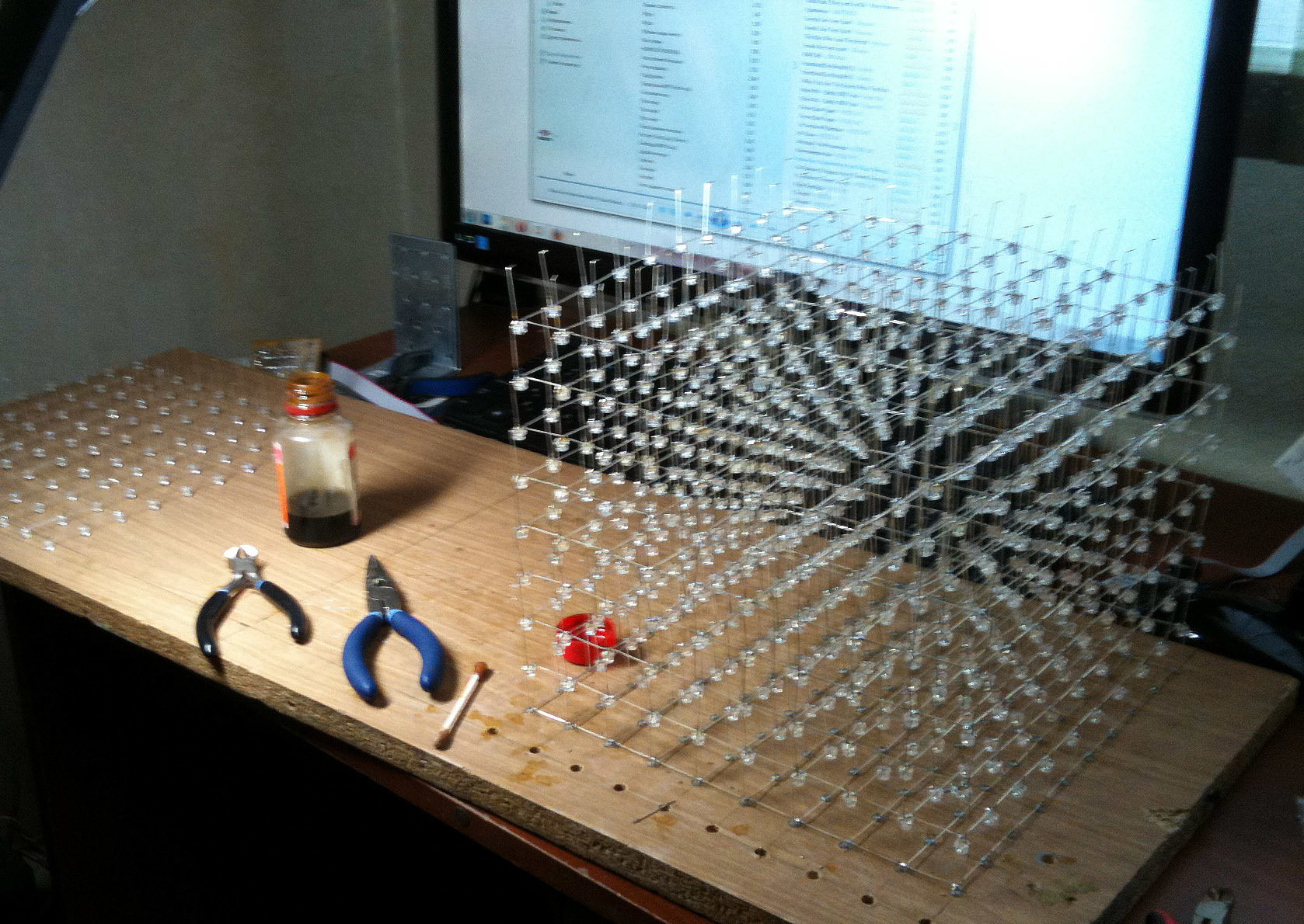
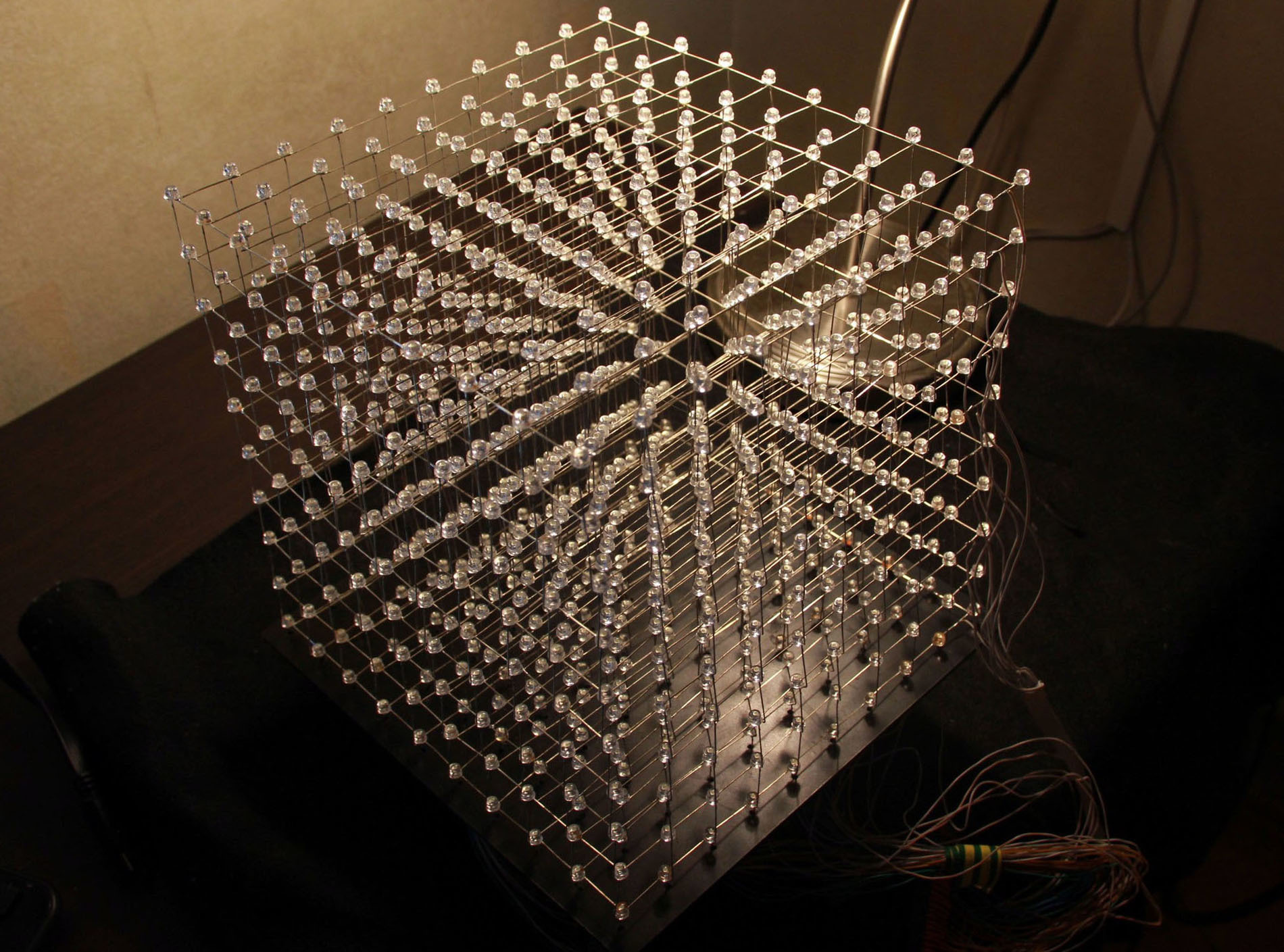
Then with Ebay I ordered 1000 diodes, and decided to assemble a very large, by my standards, cube. By the way, my small experiments led to the fact that the best choice fell on diodes with a large radiation pattern. They are not elongated, as usual, but form a hemisphere, their luminescence is visible from almost all angles, you can find them on request strawhat led. They cost more, but they shine much more effectively. Soldering a cube is another test. Here, as with the hull, my good friend helped me, since I was heavily adapted to such painstaking work. They did it like everyone else, drilling holes for the caps of the diodes, and making a 10x10 matrix. Then we solder all the floors separately, and we superimpose them on each other. The process took about 3 days, almost without a seat in front of the soldering iron.
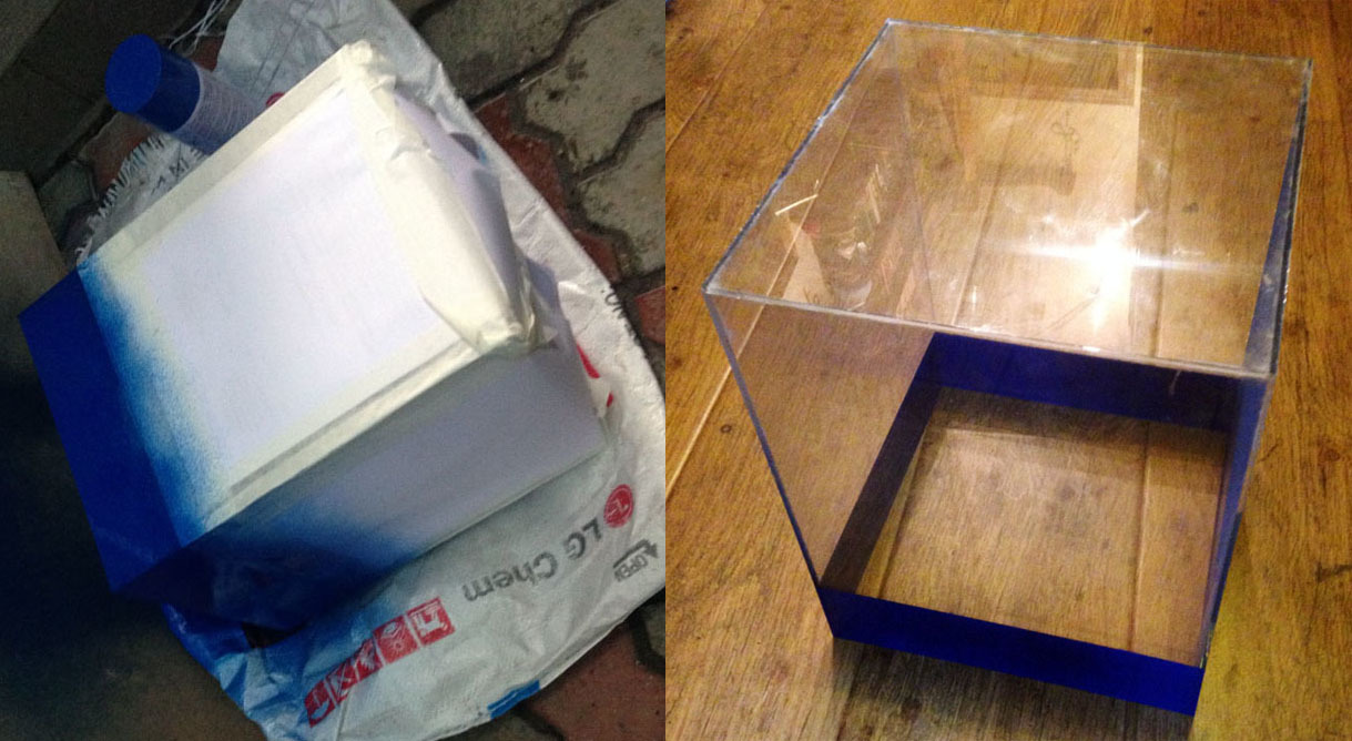
The body is made of ordinary plexiglass, which we kindly cut on laser cutting. Glued with Cosmofen PMMA, such as a special glue for plexiglass, in fact, the usual superglue copes no worse, but it requires more accuracy, because if you apply too much, you will not be able to wash it off.

On the lower platform, in advance, 100 holes for the LEDs were marked on the laser cutting. Easily drill them with a screwdriver, carefully submerge the welded cube there, and solder the adapters from below.
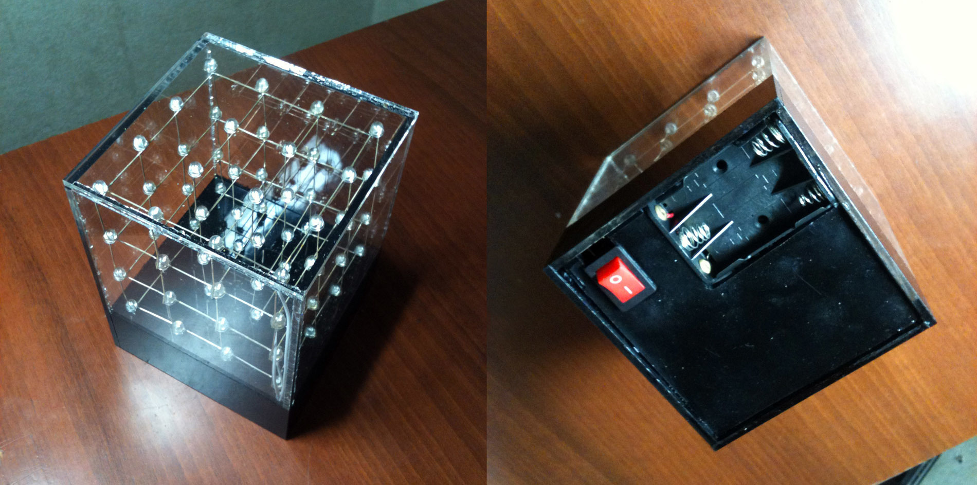
Also, to hide the electronics, I had to adjust and color the bottom of the cube. This task was simple, the main thing that we learned from the past experience of painting a small cube - you need to paint at an angle, preferably from top to bottom, so that the paint does not penetrate the glued gaps of the faces, under the action of gravity.
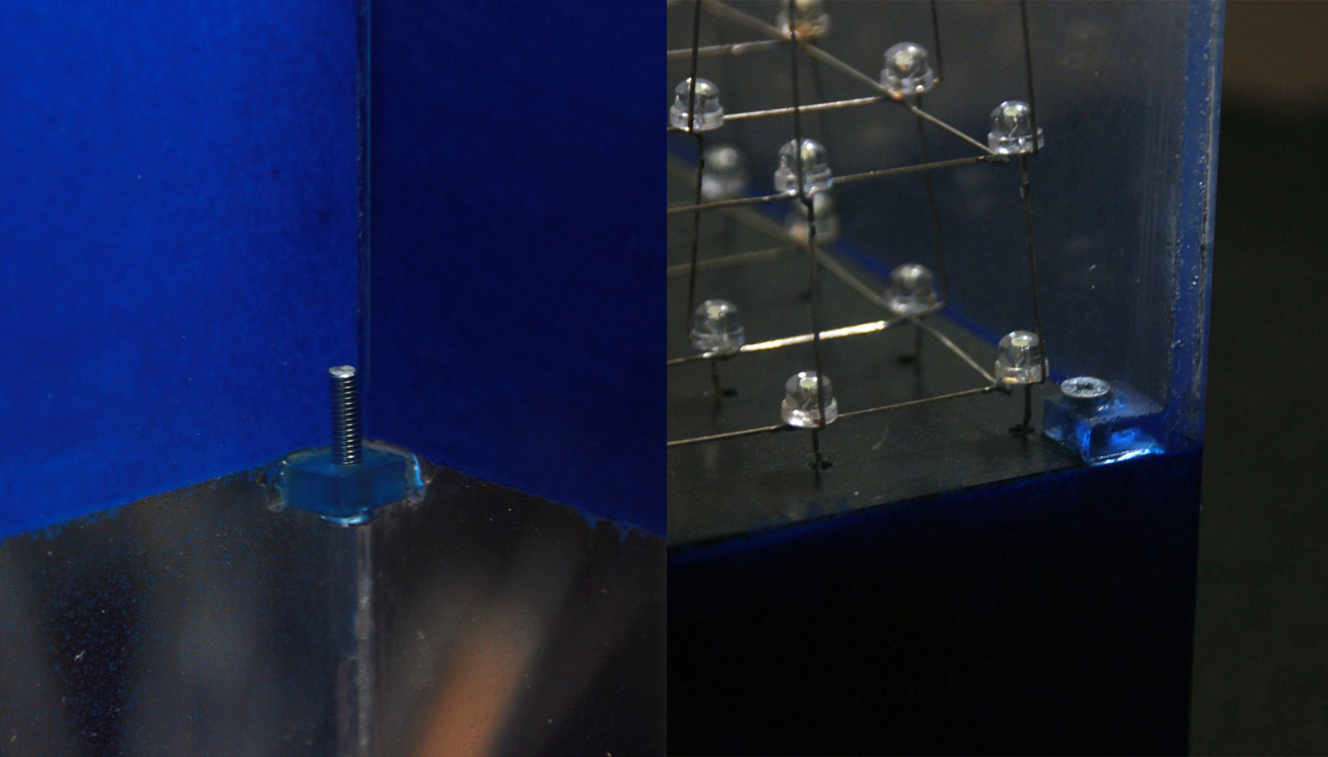
It now remained to figure out how to fix the cube with the base into a decorative case. It was necessary to fix the platform with holes at the junction with the painted part. For this, small plexiglas squares with screwed in screws were cut out. They had to be made so tiny so that the cube from the diodes could “crawl” to its rightful place. The squares were stubbornly filled with superglue, holding on perfectly. The platform itself also drilled holes, and fixed the cube with nuts.
Oh yeah, still need to talk about how we cleaned it after solder. They soldered a cube using LTI 120, respectively, all the diodes were in yellow bloom from rosin. There was no such large ultrasonic bath, and nothing was even cleaned with a brush even by hand. By the way, the diodes are slightly cloudy from acetone, which is unacceptable. The solution was found unexpectedly, through trial and error - ammonia. We loaded it into a container from a former glass cleaner - and pshikali on a cube. Then wait five minutes and rinse with water. Then again ammonia - so about four approaches and the cube began to shine clean.

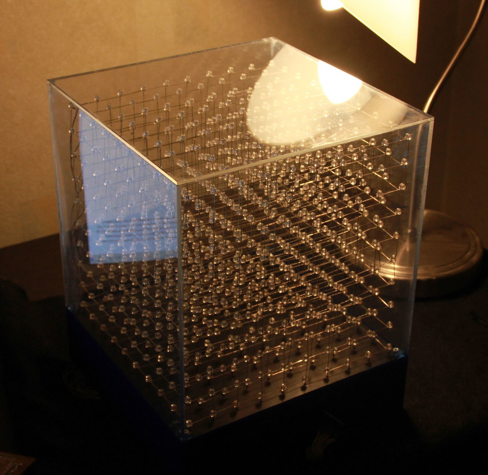
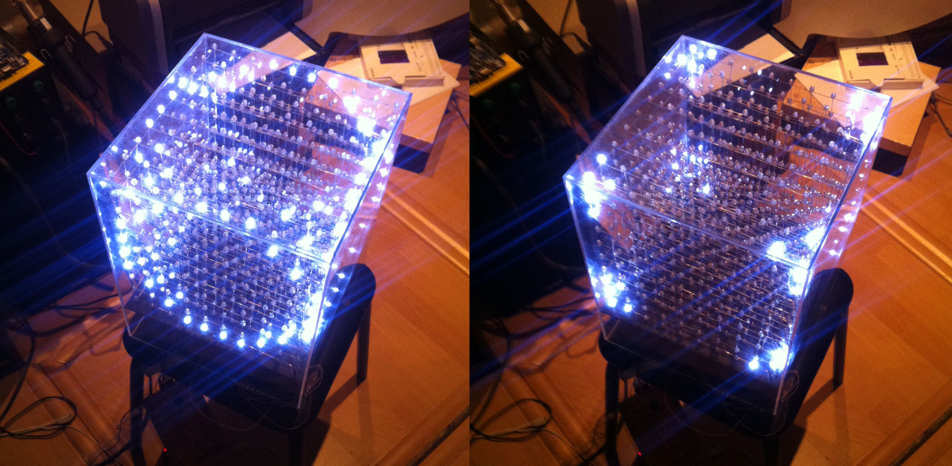
After final assembly, the cube took the following form:
Unfortunately, the electronics design process was not quite thoughtful and, as a result, the matrix was soldered by analogy with old cubes, there was a common cathode on the floors, and the columns were lit with diodes anodes. This solution is not very profitable from the point of view of supplying a large current to the column, because if in a 5-story cube for good brightness it is enough to feed one current, then in a 10-story one, at least, you need 2 times more.
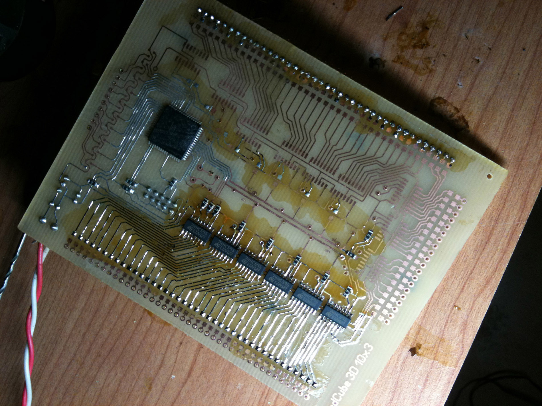
I didn’t think much about this problem and the first board was created using the well-known 74hc595 shift registers, as I already had experience with them. The switching task was performed by AtMega128 MK, and field-effect transistors controlled the current on the floors.
Having sealed all the elements and, using the same resistors, I wrote a simple program and was shocked that you can enjoy watching the cube only in the dark. In the afternoon, his brightness did not suit him, and this was not solved by software methods. The question is not complicated - I thought, and I sealed the resistors of a smaller rating, by calculating that a current of about 70 mA would go to the diodes. After switching on, the disappointment intensified even more - the cube showed almost nothing, igniting rare diodes, but brightly. Having opened the datasheet at 74hc595, everything became clear - the voltages at the outputs are normalized for currents of no more than 8 mA, and the total current through the ground and power terminals should not exceed 70 mA, which absolutely did not suit us.
Began to study chips that would be suitable for this task. In our southern capital, almost nothing was available, and even of all the datasheets of microcircuits, which are designed for high current, I began to notice one trouble - they all contain a Darlington pair on the final stage, and connect the output contact with the ground in the datasheet. For our configuration of the cube, where the cathode was on the floors, it did not fit. Having looked at the scheme of the popular uln2003 and, having seen analogs on LED matrix drivers, I realized that this solution could not be applied:
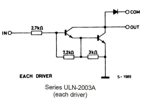
In my opinion, after examining the design of popular mis-circuits, I decided that it was easier to feed the floors plus, through a powerful transistor, and throw down the columns using the ULN2003. make a cube circuit with a common anode.
Desperate to seek a solution, the cube was postponed for an indefinite period of time, when suddenly it was suddenly needed for one event. We had three days to run it at normal brightness. The solution came up with a simple one - for each output 74hc595 we hang a normal transistor switch, and in the program we invert the bits. A bundle of some simple BC846Bs that had long been lying around with EBAY was unpacked, and the board was quickly divorced.
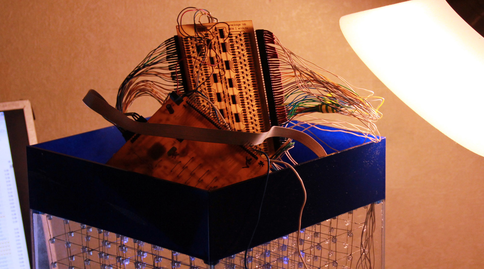
It turned out to be cumbersome, but the microcontroller was removed from it. Just from the old board had three control wires to a new one, in case we move on to stm32 in the future, or another circuit solution. After connecting all the findings, the cube started and pleased us with an excellent picture.
I didn’t find the source code for such programs anywhere, and my programming skills were far from ideal. But the result was achieved, so I will briefly describe the algorithm.
The program was written at that time in CodeVision, and the effects were loaded by a separate file in the main listing. Initially, subroutines were written for splitting a ten-digit binary number into 10 separate variables for each row, and sending these 100 variables to shift registers, zeroings, and delays to form floors. All this led to the format that described what we see on a particular floor (units are lighted diodes):
The breakdown of the number, type 0b0001111000 was carried out by a simple algorithm.
')
etc.
We check the high bit for zero or one by comparison. If more, then set the register variable to one and reduce the number by this digit. Perform this operation ten times to select all 10 values for a single row, and save them to temporary shift register variables, which we then send to display at once.
The procedure for working with a shift register does not make sense to describe it; it is disassembled on many sites. Then, after describing all 10 levels, all this is driven into a dynamic display subroutine, where the entire cycle is repeated as many times as necessary (the time of each frame is set for each frame) to deceive human vision. Of course, for large-scale cubes, writing an effect can turn into a torment, and you need to make a computer interface. But for ours, I quickly compiled a few effects, and threw it into the avrmega128 MK, taking up almost 20% of the flash memory.
And of course, what a 3d-cube without the final video. Unfortunately, I didn’t manage to adjust the settings on the camera to convey the color of the cube, the diodes merge with each other, it’s too dark, alternating with the action camera for effect.
I hope our experience in creating a cube and the allowable errors will be useful to someone, because we did it about two years ago and then there was little information on this kind of devices. I recently found it in the basement, cleaned it and put it in my store, all customers like it, everyone asks where they bought it, and almost always they watch the effects for about a couple of minutes.

I soldered the first cube somewhere in 2012, for a gift, with a resolution of 4x4x4, it used ready-made circuitry and a program found on the Internet. Having got carried away, I decided to do the same for myself, but, having increased the resolution to 5x5x5. Circuitry, based on a ready-made solution, he made himself, completely copying the very logic of applying voltage to the legs of the LEDs.
I must say, in those cubes, the voltage on the LEDs went completely from the findings of the MK, so I had to take MK with a lot of legs, because they only needed 25 columns, and 5 lines. In the gap between the MC and the LED, there was only a current-limiting resistor, and the voltage on the “floors” flowed through the field-effect transistor to the ground.
Then with Ebay I ordered 1000 diodes, and decided to assemble a very large, by my standards, cube. By the way, my small experiments led to the fact that the best choice fell on diodes with a large radiation pattern. They are not elongated, as usual, but form a hemisphere, their luminescence is visible from almost all angles, you can find them on request strawhat led. They cost more, but they shine much more effectively. Soldering a cube is another test. Here, as with the hull, my good friend helped me, since I was heavily adapted to such painstaking work. They did it like everyone else, drilling holes for the caps of the diodes, and making a 10x10 matrix. Then we solder all the floors separately, and we superimpose them on each other. The process took about 3 days, almost without a seat in front of the soldering iron.
The body is made of ordinary plexiglass, which we kindly cut on laser cutting. Glued with Cosmofen PMMA, such as a special glue for plexiglass, in fact, the usual superglue copes no worse, but it requires more accuracy, because if you apply too much, you will not be able to wash it off.
On the lower platform, in advance, 100 holes for the LEDs were marked on the laser cutting. Easily drill them with a screwdriver, carefully submerge the welded cube there, and solder the adapters from below.
Also, to hide the electronics, I had to adjust and color the bottom of the cube. This task was simple, the main thing that we learned from the past experience of painting a small cube - you need to paint at an angle, preferably from top to bottom, so that the paint does not penetrate the glued gaps of the faces, under the action of gravity.
It now remained to figure out how to fix the cube with the base into a decorative case. It was necessary to fix the platform with holes at the junction with the painted part. For this, small plexiglas squares with screwed in screws were cut out. They had to be made so tiny so that the cube from the diodes could “crawl” to its rightful place. The squares were stubbornly filled with superglue, holding on perfectly. The platform itself also drilled holes, and fixed the cube with nuts.
Oh yeah, still need to talk about how we cleaned it after solder. They soldered a cube using LTI 120, respectively, all the diodes were in yellow bloom from rosin. There was no such large ultrasonic bath, and nothing was even cleaned with a brush even by hand. By the way, the diodes are slightly cloudy from acetone, which is unacceptable. The solution was found unexpectedly, through trial and error - ammonia. We loaded it into a container from a former glass cleaner - and pshikali on a cube. Then wait five minutes and rinse with water. Then again ammonia - so about four approaches and the cube began to shine clean.
After final assembly, the cube took the following form:
Unfortunately, the electronics design process was not quite thoughtful and, as a result, the matrix was soldered by analogy with old cubes, there was a common cathode on the floors, and the columns were lit with diodes anodes. This solution is not very profitable from the point of view of supplying a large current to the column, because if in a 5-story cube for good brightness it is enough to feed one current, then in a 10-story one, at least, you need 2 times more.
I didn’t think much about this problem and the first board was created using the well-known 74hc595 shift registers, as I already had experience with them. The switching task was performed by AtMega128 MK, and field-effect transistors controlled the current on the floors.
Having sealed all the elements and, using the same resistors, I wrote a simple program and was shocked that you can enjoy watching the cube only in the dark. In the afternoon, his brightness did not suit him, and this was not solved by software methods. The question is not complicated - I thought, and I sealed the resistors of a smaller rating, by calculating that a current of about 70 mA would go to the diodes. After switching on, the disappointment intensified even more - the cube showed almost nothing, igniting rare diodes, but brightly. Having opened the datasheet at 74hc595, everything became clear - the voltages at the outputs are normalized for currents of no more than 8 mA, and the total current through the ground and power terminals should not exceed 70 mA, which absolutely did not suit us.
Began to study chips that would be suitable for this task. In our southern capital, almost nothing was available, and even of all the datasheets of microcircuits, which are designed for high current, I began to notice one trouble - they all contain a Darlington pair on the final stage, and connect the output contact with the ground in the datasheet. For our configuration of the cube, where the cathode was on the floors, it did not fit. Having looked at the scheme of the popular uln2003 and, having seen analogs on LED matrix drivers, I realized that this solution could not be applied:
In my opinion, after examining the design of popular mis-circuits, I decided that it was easier to feed the floors plus, through a powerful transistor, and throw down the columns using the ULN2003. make a cube circuit with a common anode.
Desperate to seek a solution, the cube was postponed for an indefinite period of time, when suddenly it was suddenly needed for one event. We had three days to run it at normal brightness. The solution came up with a simple one - for each output 74hc595 we hang a normal transistor switch, and in the program we invert the bits. A bundle of some simple BC846Bs that had long been lying around with EBAY was unpacked, and the board was quickly divorced.
It turned out to be cumbersome, but the microcontroller was removed from it. Just from the old board had three control wires to a new one, in case we move on to stm32 in the future, or another circuit solution. After connecting all the findings, the cube started and pleased us with an excellent picture.
I didn’t find the source code for such programs anywhere, and my programming skills were far from ideal. But the result was achieved, so I will briefly describe the algorithm.
The program was written at that time in CodeVision, and the effects were loaded by a separate file in the main listing. Initially, subroutines were written for splitting a ten-digit binary number into 10 separate variables for each row, and sending these 100 variables to shift registers, zeroings, and delays to form floors. All this led to the format that described what we see on a particular floor (units are lighted diodes):
a=0b1000000001; b=0b0000000000; c=0b0000000000; d=0b0001111000; e=0b0001111000; f=0b0001111000; g=0b0001111000; h=0b0000000000; i=0b0000000000; j=0b1000000001; addr();output_shift(); level1(); The breakdown of the number, type 0b0001111000 was carried out by a simple algorithm.
')
if (a>0b0111111111) { out[1]=1; a=a-0b1000000000; } if (a>0b0011111111) { out[2]=1; a=a-0b0100000000; } etc.
We check the high bit for zero or one by comparison. If more, then set the register variable to one and reduce the number by this digit. Perform this operation ten times to select all 10 values for a single row, and save them to temporary shift register variables, which we then send to display at once.
The procedure for working with a shift register does not make sense to describe it; it is disassembled on many sites. Then, after describing all 10 levels, all this is driven into a dynamic display subroutine, where the entire cycle is repeated as many times as necessary (the time of each frame is set for each frame) to deceive human vision. Of course, for large-scale cubes, writing an effect can turn into a torment, and you need to make a computer interface. But for ours, I quickly compiled a few effects, and threw it into the avrmega128 MK, taking up almost 20% of the flash memory.
And of course, what a 3d-cube without the final video. Unfortunately, I didn’t manage to adjust the settings on the camera to convey the color of the cube, the diodes merge with each other, it’s too dark, alternating with the action camera for effect.
I hope our experience in creating a cube and the allowable errors will be useful to someone, because we did it about two years ago and then there was little information on this kind of devices. I recently found it in the basement, cleaned it and put it in my store, all customers like it, everyone asks where they bought it, and almost always they watch the effects for about a couple of minutes.
Source: https://habr.com/ru/post/391089/
All Articles