Laboratory microwave. About datasheets on Hittite controlled power amplifiers and what they don't have
During the development of the elements of a radar station (and any kind of electronics), our engineers are often faced with the need to meticulously scan operational documentation (datasheet) for a particular product, be it a chip, a module, an assembly, or even a unit. Among our colleagues from the digital world and the world of low-frequency analog technology, there is a judgment about the incompleteness of the documentation of most top manufacturers of electronic components (components). In the microwave element base, the situation is even worse. The manufacturer of some operational amplifier (for example, Analog Devices - AD8027) at least bothers to give a detailed description of the parameters (taking into account the difference in models), several switching options, graphical dependencies for each option, etc. Of course, information is not enough. Sometimes surprises and surprises are not explained in any descriptions and documents. But if you take any component from the high-frequency family, then at the very first power-on, a whole complex of problems and problems emerge.
Detailed operational documentation should consist of several sections. Usually it is:
In the microwave technology often happened curiosities, when following all the recommendations of the datasheet did not lead to the performance of the product. Lack of experience in working with the product results in a multi-day search for solutions, cooperation with other consumers of the component, ineffective calls to the local representative of the manufacturer. All for one single chip. Especially distinguished in terms of ignorance when writing datasheets company Hittite Microwave corp. The recent takeover of Hittite by AD has inspired developers with hope for change for the better. But it was not there. Changes in the datasheets were limited to the appearance of a new title page with the image of the corporate logo and the name of Analog Devices.
The problems of the controlled power amplifier (UUM) HMC996LP4 resulted in two weeks of wasted time, sleepless nights, deadlines and other related troubles. Here is one of the problems:
')
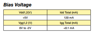
The table presented in dtsh demonstrates the voltage for turning on the SMC. If you drag a document, you will see a bunch of dependencies on the control voltage. There is nothing to mention about Vgg and Vcc. But the functional diagram in a simplified form:

From the circuit it is not visible where those Vgg and Vcc are actually connected. So we assumed, having connected the work of the UUM with the field effect transistor, that Vcc is the supply voltage, Vgg is the offset.
Here is what we see in the test parameters:
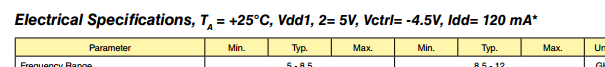
and footnote: * Set Vctrl = -4.5V and then adjust Vgg1, 2 between -2V to 0V to achieve Idd = 120 mA typical.
Thus, we are forced to first produce a mock-up, check it, select the right bias voltage (with the transistor open, by the way, the circuit lags in a short-circuit, and this in the end product can result in an unpredictable failure of other components or at least to their degradation ), only then insert the UUM in our project. De facto, the cost of the project increases, since the layout should be as close as possible constructively to the finished product (otherwise the configuration of switching on the microwave component may change).
Repeated mockery of the UUM data showed the overall repeatability of the switching configuration. Why it was impossible to present it in the document? Unless to force the consumer to buy a debug payment (it, by the way, costs very much).
Another interesting point. Here are the graphs of the gain versus frequency at different control voltages:

That's the meeting. Let us assume that the non-uniformity of the amplitude-frequency characteristic (AFC) in the part of the X-band is critically important to us - the spread of the transmission coefficient in the frequency band should not exceed 1 dB for example. It remains a mystery that you can understand from such a schedule, because It is clearly smoothed in order to scale. It turns out, buying a microcircuit, we already risk falling into an awkward situation when the product obviously does not suit us.
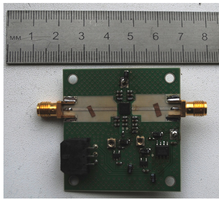
As a result, we buy UUM at our own risk, develop and manufacture a prototyping board, carry out installation and measurements.
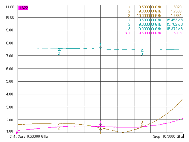
The graphs show the gain in the maximum gain mode, VSWR input / output.
The bias voltage was chosen -0.8 V. The noise factor, by the way, very much depends on the quality of the power sources. The typical value is Kr = 3.5 dB for these frequencies (and not 2 dB, as indicated in dtsh).
Well, the last subtlety: two-stage (and more) switching on of such amplifiers is prone to unstable operation. The problem is solved by spacing the amplifiers at a respectful distance, shielding the stages.
Detailed operational documentation should consist of several sections. Usually it is:
- Appearance of the product (possible variants of the case), name, type, brief description of the functional, functional diagram, pinout;
- The value of typical parameters inherent in all components of this class (the same current consumption at a given supply voltage);
- Test parameters (welcome as much as possible detailed description of all values that lies behind them) with different configurations of inclusion;
- Graphical dependencies for as many characteristics as possible;
- Maximum allowable values of the element parameters (limiting supply voltage, input power, etc.);
- Detailed description of the pins / ports, indicating the functional, equivalent circuit, input / output resistance, recommended body kit, braces;
- Recommended inclusion schemes with an indication of the principle of calculating body kit (voltage dividers, external filters, etc.) and a detailed description of the principle of operation;
- Variants of the topology of test printed circuit boards with an indication of the subtleties of the trace (for example, the preferred distance between conductors or body kit elements, the dimensions of the landing pad, the protective zone for installation, the heat sink);
- Configuration, types of enclosures with sizes, the difference indexes / prefixes;
- Of course, a competent engineer is able to think out a lot of things written by himself and accept the most correct algorithm for working with a component. Gained experience allows you to save time on reading all the documentation, focus only on the most important points.
In the microwave technology often happened curiosities, when following all the recommendations of the datasheet did not lead to the performance of the product. Lack of experience in working with the product results in a multi-day search for solutions, cooperation with other consumers of the component, ineffective calls to the local representative of the manufacturer. All for one single chip. Especially distinguished in terms of ignorance when writing datasheets company Hittite Microwave corp. The recent takeover of Hittite by AD has inspired developers with hope for change for the better. But it was not there. Changes in the datasheets were limited to the appearance of a new title page with the image of the corporate logo and the name of Analog Devices.
The problems of the controlled power amplifier (UUM) HMC996LP4 resulted in two weeks of wasted time, sleepless nights, deadlines and other related troubles. Here is one of the problems:
')
The table presented in dtsh demonstrates the voltage for turning on the SMC. If you drag a document, you will see a bunch of dependencies on the control voltage. There is nothing to mention about Vgg and Vcc. But the functional diagram in a simplified form:
From the circuit it is not visible where those Vgg and Vcc are actually connected. So we assumed, having connected the work of the UUM with the field effect transistor, that Vcc is the supply voltage, Vgg is the offset.
Here is what we see in the test parameters:
and footnote: * Set Vctrl = -4.5V and then adjust Vgg1, 2 between -2V to 0V to achieve Idd = 120 mA typical.
Thus, we are forced to first produce a mock-up, check it, select the right bias voltage (with the transistor open, by the way, the circuit lags in a short-circuit, and this in the end product can result in an unpredictable failure of other components or at least to their degradation ), only then insert the UUM in our project. De facto, the cost of the project increases, since the layout should be as close as possible constructively to the finished product (otherwise the configuration of switching on the microwave component may change).
Repeated mockery of the UUM data showed the overall repeatability of the switching configuration. Why it was impossible to present it in the document? Unless to force the consumer to buy a debug payment (it, by the way, costs very much).
Another interesting point. Here are the graphs of the gain versus frequency at different control voltages:
That's the meeting. Let us assume that the non-uniformity of the amplitude-frequency characteristic (AFC) in the part of the X-band is critically important to us - the spread of the transmission coefficient in the frequency band should not exceed 1 dB for example. It remains a mystery that you can understand from such a schedule, because It is clearly smoothed in order to scale. It turns out, buying a microcircuit, we already risk falling into an awkward situation when the product obviously does not suit us.
As a result, we buy UUM at our own risk, develop and manufacture a prototyping board, carry out installation and measurements.
The graphs show the gain in the maximum gain mode, VSWR input / output.
The bias voltage was chosen -0.8 V. The noise factor, by the way, very much depends on the quality of the power sources. The typical value is Kr = 3.5 dB for these frequencies (and not 2 dB, as indicated in dtsh).
Well, the last subtlety: two-stage (and more) switching on of such amplifiers is prone to unstable operation. The problem is solved by spacing the amplifiers at a respectful distance, shielding the stages.
Source: https://habr.com/ru/post/390969/
All Articles