Full circuit design of active CMC and charger for UPS 3 kW
Part 1
Part 2
Part 3
Part 4.1
Part 4.2
Part 5
Part 6
After the publication of articles No. 5 and No. 6 from the cycle on the UPS, I decided to check them in "iron". It is worth remembering that all the articles in the cycle are adapted for self-assembly options for my commercial projects, so I think it’s blasphemous to give naked without confirmation. I can say right away - the result was worse than expected at times! Need to recycle!
I also ask you to pay attention that in this article I am posting the scheme of a completely finished device! They went to it : active power corrector + charger power board + charger control board + stand-by power supply circuit (from part 3 ).
Another very important point : everyone who has already bought KIT kits for me to assemble the UPS received this particular circuit design! So, we do not worry - you got the best product!
It is worth noting that the option from part 5 and part 6 is also working and is taking place at least because it turned out to be 20% cheaper, but this is a reason!
I will not torment and immediately show the final version of the circuitry, which I got and meets all the previously stated requirements, and most importantly, I worked steadily under 110-120% load for 3 weeks . Therefore, with a clear conscience, I present to you the final version:
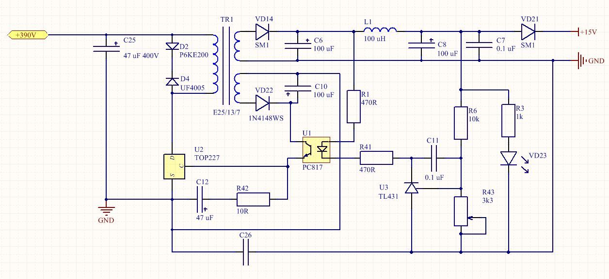
Figure 1 - Scheme of the implementation of standby power, familiar from part 3

Figure 2 - Control board with generator, drivers and protections
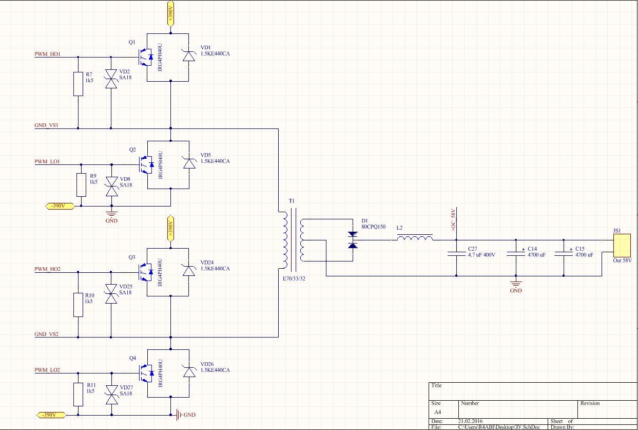
Figure 3 - The power part of the charger

Figure 4 - Diagram of the active power factor corrector

Figure 5 - A single board, containing all the parts described above, the dimensions are 300x200 mm with a copper thickness of 105 microns (Resonit will do this)
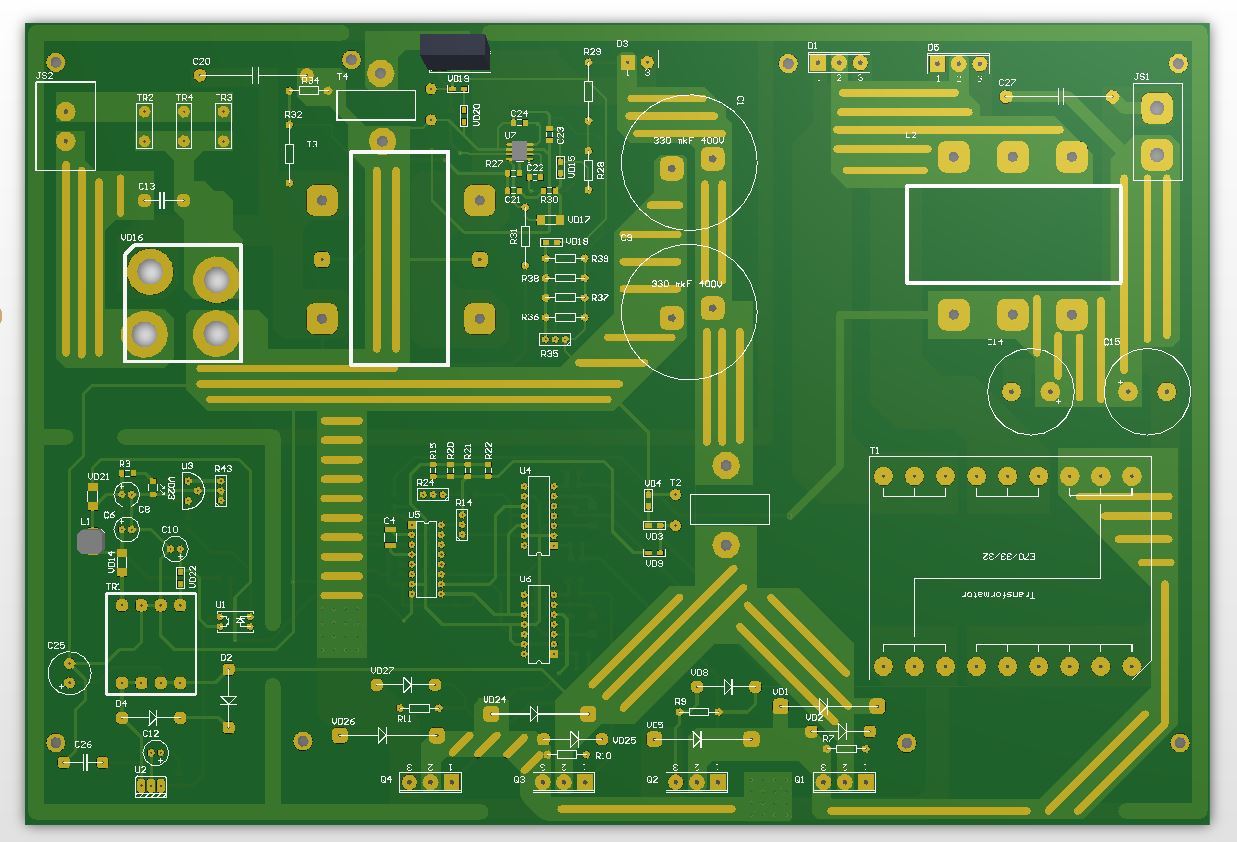
Figure 6 - A bit of visibility, the top layer (Top Layer)
Download device design in Altium Designer 15
And so I assembled the power corrector (hereinafter referred to as CMC) according to the L6561-based datasheet scheme , the result of this decision made me very happy. Although I used to assemble shemki on it, but at capacities up to 500 W , I was pleasantly surprised that the controller showed itself well in the 3000 W version ! But you understand perfectly well - if I reworked something, then the output turned out to be ashitty device with unsatisfactory characteristics, but I don’t like it at all! What is the trouble:
1) The theoretical calculation of the output capacity (electrolyte) was far from reality. Therefore, it was decided to increase the capacity from 220 µF to 440 µF.
2) The CCM choke calculated at 60 kHz turned out to be my failure ... The PWM frequency at the output of L6561 varies from 20 to 150 kHz and this is not programmed at all. I simply forgot to take into account that this controller regulates as a TM, what it is that can be read in the LH on it or on the Kompala website.
3) IGBT key was not able to work at such frequencies, after 80 kHz, terrible switching / dynamic losses began for this one option - to apply a powerful field effect transistor and the choice fell on the FCH35N60. This is the key for 35A and 600V, capable of operating up to 200 kHz - I did not check it above.
4) I realized the frequency on which the throttle should be calculated, only after the results have been carried out, I cannot understand this by datasheet - simply because this controller is positioned up to 300 W. The frequency chosen is 110 kHz.
5) I would like to point out by a separate item that I managed to fit the choke on a single core of -52 material with dimensions 57x35x25 mm by increasing the frequency and the new key!
And this is a problem only with CCM! After solving them, the corrector acquired a very diligent look, in the range of 165-235V AC after the diode bridge the temperature does not rise above 65 degrees. In the range of 85-280V AC, the temperature never reached more than 115 degrees! This is victory!))
- The microcircuit is suitable for a power of approximately 5-6 kW, that is, for any single-phase solution;
- Output capacity must be chosen based on 125 μF per 1 kW of power;
- On the winding of the current form control (ZDC) one turn is enough;
- In KKM there is no place for IGBT transistors
My main mistake was topology . Diagonal bridge - the most adored topology by me! But alas, I refused it ... The trouble was that during long work at nominal load and in overload mode, the efficiency dropped to a negligible 80-82%! I had a problem - the efficiency of the “slanting bridge” on loads up to 60-80% and rare transitions up to 100% was about 92%, which pleased me. I am also impressed by the repeatability of this topology, but the low efficiency during long-term operation at 100-120% of the nominal value was straining. Yes, in this mode, the UPS works sooooo rarely, because the rule of good tone is considered to be loaded UPS at 60-70%. Only considering my experience in commercial projects, I realized one thing - one must do so that even a complete moron could not kill the device! After that, everything became obvious - a full bridge! (N-bridge).
I think everything is very clear here - I had to essentially develop a new device and run it in, which is why the release of the article was delayed.
1) "Oblique bridge" can be used if you are not going to force the UPS and you have to power the server rack from it. That is, operate in a soft mode and without long overloads;
2) H-bridge is used if you are an inadequate maniac and just burn with the desire to power 24/7 from the UPS 3.3-kW asynchronous motor! Well, we decided to non-stop to cook sheets of metal from 10 mm))) In general, the topology for serious guys!
3) It is necessary to choose a topology for your needs and tasks.
4) I did not see the meaning of the galvanic isolation in these parts.
5) 48V is acceptable for 3-4 kW, but it is better to raise the DC bus voltage to at least 96-120V (8-10 small batteries for 17 or 27 A * h), ideally 240V (20 small batteries for 12 A * h)
I told how to make a transformer and calculate it in part 2, I advise you to refresh your memory for those who decide to assemble this circuit. There is just an example of an N-bridge article written that will please you))

Figure 7 - Calculation of coil data transformer 390-58V for the charger

Figure 8 - Calculation of the output choke

Figure 9 - Calculation of the power choke of CMC (the second winding 1 turn)
That's probably all, we are exploring a new solution, lit up and ask the questions that have appeared - as usual I will try to answer and help them!))
The same news is for those who did not get KIT sets - a new delivery of 50 sets will take place on February 25-26! As before, you can purchase: boards, stitched and soldered STM32 microcontrollers, as well as a complete set with accessories and radiators!
By the way, the video has already been filmed, it remains only to process it to a more or less adequate state)) If you want to help, write me by mail or VK!
Part 2
Part 3
Part 4.1
Part 4.2
Part 5
Part 6
As usual, small lyrics ... Comrades! Those who take and publish my articles, materials and other nishtyaki - please indicate this author and the source.
I think everyone understands that I can tritely sell my projects or make a leap for coins and buy it all, but I don’t want to do it. I want to give people good, chewed projects and training materials that you will not find anywhere else, and moreover you will not get help in assembling and consulting for many hours. I post the source of all files completely free of charge and offer several options in order to save your money!
')
For all my efforts, I do not demand any gratitude, it is enough for me that you read and you like my little articles, my work)) But please, do not steal the material and don’t assign your authorship to them! So that the admins of third-party sites did not write to me and did not ask me to delete my articles, stating that I am not the author, but Vasily Petrovich Zalupkin, who the real author published these articles on his website! And do not care that 2 months later ...
I hope those who did this will hear me and be more honest, not even with me, but with myself. Thanks for attention!))
After the publication of articles No. 5 and No. 6 from the cycle on the UPS, I decided to check them in "iron". It is worth remembering that all the articles in the cycle are adapted for self-assembly options for my commercial projects, so I think it’s blasphemous to give naked without confirmation. I can say right away - the result was worse than expected at times! Need to recycle!
I also ask you to pay attention that in this article I am posting the scheme of a completely finished device! They went to it : active power corrector + charger power board + charger control board + stand-by power supply circuit (from part 3 ).
Another very important point : everyone who has already bought KIT kits for me to assemble the UPS received this particular circuit design! So, we do not worry - you got the best product!
Circuit design of a powerful charger with an active power factor corrector
It is worth noting that the option from part 5 and part 6 is also working and is taking place at least because it turned out to be 20% cheaper, but this is a reason!
I will not torment and immediately show the final version of the circuitry, which I got and meets all the previously stated requirements, and most importantly, I worked steadily under 110-120% load for 3 weeks . Therefore, with a clear conscience, I present to you the final version:
Figure 1 - Scheme of the implementation of standby power, familiar from part 3
Figure 2 - Control board with generator, drivers and protections
Figure 3 - The power part of the charger
Figure 4 - Diagram of the active power factor corrector
Figure 5 - A single board, containing all the parts described above, the dimensions are 300x200 mm with a copper thickness of 105 microns (Resonit will do this)
Figure 6 - A bit of visibility, the top layer (Top Layer)
Download device design in Altium Designer 15
Description of problems and methods of their solution
And so I assembled the power corrector (hereinafter referred to as CMC) according to the L6561-based datasheet scheme , the result of this decision made me very happy. Although I used to assemble shemki on it, but at capacities up to 500 W , I was pleasantly surprised that the controller showed itself well in the 3000 W version ! But you understand perfectly well - if I reworked something, then the output turned out to be a
1) The theoretical calculation of the output capacity (electrolyte) was far from reality. Therefore, it was decided to increase the capacity from 220 µF to 440 µF.
2) The CCM choke calculated at 60 kHz turned out to be my failure ... The PWM frequency at the output of L6561 varies from 20 to 150 kHz and this is not programmed at all. I simply forgot to take into account that this controller regulates as a TM, what it is that can be read in the LH on it or on the Kompala website.
3) IGBT key was not able to work at such frequencies, after 80 kHz, terrible switching / dynamic losses began for this one option - to apply a powerful field effect transistor and the choice fell on the FCH35N60. This is the key for 35A and 600V, capable of operating up to 200 kHz - I did not check it above.
4) I realized the frequency on which the throttle should be calculated, only after the results have been carried out, I cannot understand this by datasheet - simply because this controller is positioned up to 300 W. The frequency chosen is 110 kHz.
5) I would like to point out by a separate item that I managed to fit the choke on a single core of -52 material with dimensions 57x35x25 mm by increasing the frequency and the new key!
And this is a problem only with CCM! After solving them, the corrector acquired a very diligent look, in the range of 165-235V AC after the diode bridge the temperature does not rise above 65 degrees. In the range of 85-280V AC, the temperature never reached more than 115 degrees! This is victory!))
Gained knowledge and experience (for me personally):
- The microcircuit is suitable for a power of approximately 5-6 kW, that is, for any single-phase solution;
- Output capacity must be chosen based on 125 μF per 1 kW of power;
- On the winding of the current form control (ZDC) one turn is enough;
- In KKM there is no place for IGBT transistors
Bug fixing with charger
My main mistake was topology . Diagonal bridge - the most adored topology by me! But alas, I refused it ... The trouble was that during long work at nominal load and in overload mode, the efficiency dropped to a negligible 80-82%! I had a problem - the efficiency of the “slanting bridge” on loads up to 60-80% and rare transitions up to 100% was about 92%, which pleased me. I am also impressed by the repeatability of this topology, but the low efficiency during long-term operation at 100-120% of the nominal value was straining. Yes, in this mode, the UPS works sooooo rarely, because the rule of good tone is considered to be loaded UPS at 60-70%. Only considering my experience in commercial projects, I realized one thing - one must do so that even a complete moron could not kill the device! After that, everything became obvious - a full bridge! (N-bridge).
I think everything is very clear here - I had to essentially develop a new device and run it in, which is why the release of the article was delayed.
The experience I received from this work:
1) "Oblique bridge" can be used if you are not going to force the UPS and you have to power the server rack from it. That is, operate in a soft mode and without long overloads;
2) H-bridge is used if you are an inadequate maniac and just burn with the desire to power 24/7 from the UPS 3.3-kW asynchronous motor! Well, we decided to non-stop to cook sheets of metal from 10 mm))) In general, the topology for serious guys!
3) It is necessary to choose a topology for your needs and tasks.
4) I did not see the meaning of the galvanic isolation in these parts.
5) 48V is acceptable for 3-4 kW, but it is better to raise the DC bus voltage to at least 96-120V (8-10 small batteries for 17 or 27 A * h), ideally 240V (20 small batteries for 12 A * h)
Calculation of the transformer and chokes
I told how to make a transformer and calculate it in part 2, I advise you to refresh your memory for those who decide to assemble this circuit. There is just an example of an N-bridge article written that will please you))
Figure 7 - Calculation of coil data transformer 390-58V for the charger
Figure 8 - Calculation of the output choke
Figure 9 - Calculation of the power choke of CMC (the second winding 1 turn)
Epilogue
That's probably all, we are exploring a new solution, lit up and ask the questions that have appeared - as usual I will try to answer and help them!))
The same news is for those who did not get KIT sets - a new delivery of 50 sets will take place on February 25-26! As before, you can purchase: boards, stitched and soldered STM32 microcontrollers, as well as a complete set with accessories and radiators!
By the way, the video has already been filmed, it remains only to process it to a more or less adequate state)) If you want to help, write me by mail or VK!
Source: https://habr.com/ru/post/390699/
All Articles