Click the relay correctly: switching of powerful loads
Hi, Geektimes!
Managing powerful loads is quite a popular topic among people who somehow relate to home automation, and in general, regardless of the platform: whether it is Arduino, Rapsberry Pi, Unwired One or another platform, turn on or off some heater, boiler or channel fan sooner or later have to.
The traditional dilemma here is - how to actually commute. As many were convinced by their sad experience, the Chinese relays do not have adequate reliability - when switching a powerful inductive load, the contacts sparkle strongly, and at one fine moment they can simply stick. It is necessary to put two relays - the second for safety on opening.
')
Instead of a relay, you can put a triac or solid-state relay (in fact, the same thyristor or field device with a logic signal and opto-decoupling control circuit in one package), but they have another minus - they heat up. Accordingly, a radiator is needed, which increases the size of the structure.
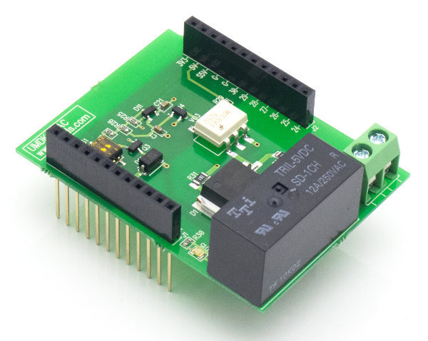
I want to tell you about a simple and rather obvious, but at the same time rarely found scheme that can do this:
But first - a bit of illustrations. In all cases, TTI relays of the TRJ and TRIL series were used, and a 650 W vacuum cleaner was used as a load.
The classical scheme - we connect the vacuum cleaner through a conventional relay. Then we connect an oscilloscope to the vacuum cleaner (Caution! Either an oscilloscope, or a vacuum cleaner - or better both - should be electrically isolated from the ground! Do not climb fingers with eggs and salt shakers!) And watch.
Include:

It was necessary almost to the maximum of the mains voltage (trying to bind the electromagnetic relay to zero crossing is a perilous task: it is too slow). In both directions, the babakhnulo was shortly discharged from almost vertical fronts, and noise was flying in all directions. Expected.
Turn off:

The sudden loss of voltage on an inductive load does not bode well - the surge has flown up. In addition, you see this interference on a sine wave for milliseconds before the actual shutdown? This sparking started to open the contacts of the relay, because of which they once and stick.
So, the “bare” relay to switch the inductive load is bad. What will we do? Let's try to add snubber - RC-chain of 120 Ohm resistor and 0.15 uF capacitor.
Include:

Better, but not much. Emission slowed down in height, but generally preserved.
Turn off:

Same picture. The garbage remained, moreover, the sparking of the relay contacts remained, albeit greatly reduced.
Conclusion: it is better with snubber than without snabber, but globally it does not solve problems. However, if you want to switch inductive loads with an ordinary relay, put a snubber. The ratings must be selected for a specific load, but a 1-W resistor for 100-120 ohms and a capacitor for 0.1 microfarads look like a reasonable option for this case.
References: Agilent - Application Note 1399, “ Maximizing the Life Span of Your Relays ”. When the relay is working for the worst type of load, the motor, which, in addition to inductance, also has very low resistance at start-up, good authors recommend reducing the passport life of the relay by five times .
And now we will make a knight's move - we will combine a triac, a triac driver with zero detection and a relay in one circuit.
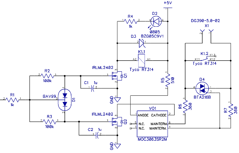
What is on this scheme? On the left is the entrance. When “1” is fed to it, the capacitor C2 is almost instantly charged through R1 and the lower half of D1; the opto-switch VO1 turns on, waits for the nearest zero crossing (MOC3063 - with integrated zero detector circuit) and turns on the D4 triac. Load starts.
Capacitor C1 is charged through a chain of R1 and R2, which takes approximately t = RC ~ 100 ms. These are several periods of mains voltage, that is, during this time the triac will have time to turn on guaranteed. Next, Q1 opens - and the K1 relay turns on (as well as the D2 LED, which shines with a pleasant emerald light). The relay contacts shunt the triac, so further - until the shutdown itself - it does not take part in the work. And not heated.
Turning off - in reverse order. As soon as “0” appears at the input, C1 discharges quickly through the upper arm D1 and R1, the relay turns off. But the triac remains on for about 100 ms, since C2 is discharged through 100-kilohm R3. Moreover, since the triac is held open by the current, even after turning off VO1, it will remain open until the load current in the next half-period drops below the triac holding current.
Turning on:

Shutdown:

Beautiful, isn't it? Moreover, when using modern triacs that are resistant to rapid changes in current and voltage (all major manufacturers have such models - NXP, ST, Onsemi, etc., the names begin with “BTA”), they are not needed at all, in any form.
Moreover, if you remember the smart people from Agilent and see how the current consumed by the motor changes, you get this picture:

The starting current is more than four times the working current. For the first five periods - the time for which the triac is ahead of the relay in our circuit - the current drops about twice, which also significantly softens the requirements for the relay and prolongs its life.
Yes, the circuit is more complicated and more expensive than a regular relay or a simple triac. But often it is worth it.
Managing powerful loads is quite a popular topic among people who somehow relate to home automation, and in general, regardless of the platform: whether it is Arduino, Rapsberry Pi, Unwired One or another platform, turn on or off some heater, boiler or channel fan sooner or later have to.
The traditional dilemma here is - how to actually commute. As many were convinced by their sad experience, the Chinese relays do not have adequate reliability - when switching a powerful inductive load, the contacts sparkle strongly, and at one fine moment they can simply stick. It is necessary to put two relays - the second for safety on opening.
')
Instead of a relay, you can put a triac or solid-state relay (in fact, the same thyristor or field device with a logic signal and opto-decoupling control circuit in one package), but they have another minus - they heat up. Accordingly, a radiator is needed, which increases the size of the structure.
I want to tell you about a simple and rather obvious, but at the same time rarely found scheme that can do this:
- Galvanic isolation of input and load
- Switching inductive loads without surge current and voltage
- No significant heat generation even at maximum power
But first - a bit of illustrations. In all cases, TTI relays of the TRJ and TRIL series were used, and a 650 W vacuum cleaner was used as a load.
The classical scheme - we connect the vacuum cleaner through a conventional relay. Then we connect an oscilloscope to the vacuum cleaner (Caution! Either an oscilloscope, or a vacuum cleaner - or better both - should be electrically isolated from the ground! Do not climb fingers with eggs and salt shakers!) And watch.
Include:
It was necessary almost to the maximum of the mains voltage (trying to bind the electromagnetic relay to zero crossing is a perilous task: it is too slow). In both directions, the babakhnulo was shortly discharged from almost vertical fronts, and noise was flying in all directions. Expected.
Turn off:
The sudden loss of voltage on an inductive load does not bode well - the surge has flown up. In addition, you see this interference on a sine wave for milliseconds before the actual shutdown? This sparking started to open the contacts of the relay, because of which they once and stick.
So, the “bare” relay to switch the inductive load is bad. What will we do? Let's try to add snubber - RC-chain of 120 Ohm resistor and 0.15 uF capacitor.
Include:
Better, but not much. Emission slowed down in height, but generally preserved.
Turn off:
Same picture. The garbage remained, moreover, the sparking of the relay contacts remained, albeit greatly reduced.
Conclusion: it is better with snubber than without snabber, but globally it does not solve problems. However, if you want to switch inductive loads with an ordinary relay, put a snubber. The ratings must be selected for a specific load, but a 1-W resistor for 100-120 ohms and a capacitor for 0.1 microfarads look like a reasonable option for this case.
References: Agilent - Application Note 1399, “ Maximizing the Life Span of Your Relays ”. When the relay is working for the worst type of load, the motor, which, in addition to inductance, also has very low resistance at start-up, good authors recommend reducing the passport life of the relay by five times .
And now we will make a knight's move - we will combine a triac, a triac driver with zero detection and a relay in one circuit.
What is on this scheme? On the left is the entrance. When “1” is fed to it, the capacitor C2 is almost instantly charged through R1 and the lower half of D1; the opto-switch VO1 turns on, waits for the nearest zero crossing (MOC3063 - with integrated zero detector circuit) and turns on the D4 triac. Load starts.
Capacitor C1 is charged through a chain of R1 and R2, which takes approximately t = RC ~ 100 ms. These are several periods of mains voltage, that is, during this time the triac will have time to turn on guaranteed. Next, Q1 opens - and the K1 relay turns on (as well as the D2 LED, which shines with a pleasant emerald light). The relay contacts shunt the triac, so further - until the shutdown itself - it does not take part in the work. And not heated.
Turning off - in reverse order. As soon as “0” appears at the input, C1 discharges quickly through the upper arm D1 and R1, the relay turns off. But the triac remains on for about 100 ms, since C2 is discharged through 100-kilohm R3. Moreover, since the triac is held open by the current, even after turning off VO1, it will remain open until the load current in the next half-period drops below the triac holding current.
Turning on:
Shutdown:
Beautiful, isn't it? Moreover, when using modern triacs that are resistant to rapid changes in current and voltage (all major manufacturers have such models - NXP, ST, Onsemi, etc., the names begin with “BTA”), they are not needed at all, in any form.
Moreover, if you remember the smart people from Agilent and see how the current consumed by the motor changes, you get this picture:
The starting current is more than four times the working current. For the first five periods - the time for which the triac is ahead of the relay in our circuit - the current drops about twice, which also significantly softens the requirements for the relay and prolongs its life.
Yes, the circuit is more complicated and more expensive than a regular relay or a simple triac. But often it is worth it.
Source: https://habr.com/ru/post/390601/
All Articles