ESP8266 and Arduino, connection, pinout
Hi geektimes . The ESP8266 theme, like IoT (Internet of Things) , is increasingly gaining popularity, and Arduino is already taking the initiative by adding these Wi-Fi modules to the list of supported cards.
But how to connect it to arduino? And is it possible to somehow do without Arduino at all? Today this is exactly what will be discussed in this article.
Looking ahead, I will say that there will be a second article, already more practical, on the topic of firmware and programming of the ESP8266 module in the Arduino IDE development environment. But first things first.
')
This video completely duplicates the material presented in the article.
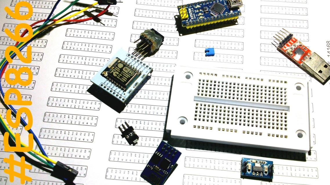
At the moment, there are many variations of this module, here are some of them:

But pinout ESP01, ESP03, ESP12:
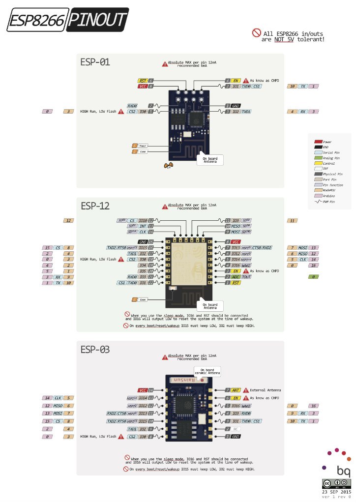
* This picture can be viewed in high quality off. site pighixxx.com .
Personally, I like the ESP07 version the most. At least for the fact that there is a metal screen (it protects the chips from external interference, thereby providing a more stable operation), its own ceramic antenna, a connector for an external antenna. It turns out that by connecting an external antenna to it, such as a biquadrate , you can achieve a good range. In addition, there are a lot of input / output ports, the so-called GPIO (General Purpose Input Output - general purpose input-output ports), by analogy with arduino-pins.
Let's go back to oursheep Wi-Fi modules and Arduino. In this article, I will look at connecting the ESP8266 (model ESP01) to the Arduino Nano V3.
But, this information will be relevant for most ESP8266 modules and various Arduino boards as well, for example, the most popular Arduino UNO.
A couple of words on ESP01 legs:

Vcc and GND (in the picture above it is 8 and 1) - power supply, Vcc can be supplied to the leg, according to the documentation , from 3 to 3.6 V , and GND - ground (power supply minus). I saw one person connect this module to two AA batteries (the supply voltage in this case was about 2.7 V) and the module was operational. But nevertheless, the developers indicated the voltage range in which the module should work, if you use another, your problems.
Attention! This module is based on 3.3 V logic, and the Arduino basically - 5 V logic. 5 E can easily be damaged by ESP8266, therefore it must be powered separately from the Arduino .
- There is a leg on my arduinka, where 3.3 V is written, why not use it?
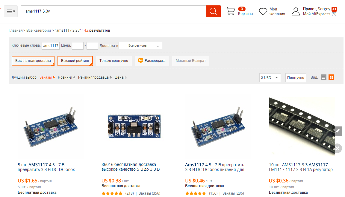
Probably you will think. The fact is that the ESP8266 is quite a voracious module, and in peaks it can consume currents up to 200 mA, and almost no arduinka is by default capable of delivering such a current, except the Arduino Due , which has a current of 3.3 V can reach 800 mA, which is enough with a margin, in other cases I advise you to use an additional 3.3 V stabilizer, for example AMS1117 3.3 V. Such shaft in both China and us.
RST 6 leg - is designed to “iron” to reload the module, briefly applying a low logic level to it, the module to reboot. Although I ignored this in the video, I still advise you to “press” this leg with a 10 kΩ resistor to the power supply in order to achieve better stability in the module, otherwise I rebooted from the slightest interference.
The CP_PD 4 leg (or in a different way EN ) serves, again, for the “iron” transfer of the module to the energy-saving mode, in which it consumes a very small current. Well, again - it would not be superfluous to “press” this leg with a 10 kΩ resistor to the positive power supply. In the video, I stupidly short-circuited this leg on Vcc, because there was no such resistor at hand.
Legs RXD0 7 TXD0 2 - hardware UART, which is used for flashing, but nobody forbids using these ports as GPIO (GPIO3 and GPIO1, respectively). For some reason, GPIO3 in the picture is not marked, but in the datasheet it is:

By the way, the “Connect” LED is connected to the TXD0 2 leg, and it is lit at a low logic level on GPIO1, well, or when the module sends something over the UART.
GPIO0 5 - can be not only an I / O port, but also put the module into programming mode. This is done by connecting this port to a low logic level (“pressing” to GND) and applying power to the module. In the video, I do it with a regular button. After flashing, do not forget to pull out the jumper / release the button (it is not necessary to hold the button during flashing, the module switches to programming mode when it is turned on, and remains in it until the reboot).
GPIO2 3 - I / O port.
And one more important moment, each GPIO Wi-Fi module can safely deliver current up to 6 mA , in order not to burn it, be sure to put resistors in series with input / output ports on ... Remember Ohm's law R = U / I = 3.3V / 0.006 A = 550 ohms, that is, 560 ohms . Or ignore it, and then wonder why it does not work.
In ESP01, all GPIOs support PWM, so that we can connect the engine driver to our four GPIOs, that is, GPIO0-3, ala L293 / L298 and steer by two engines, for example, boats, or make RGB Wi-Fi Pribluda. Yes, yes, this module has a lot of things on board, and for unpretentious projects the Arduinoviolinist is not needed, only for flashing. And if you use ESP07, then there are generally ports almost like Uno, which makes it possible to do confidently without arduino. True, there is one unpleasant moment, the ESP01 has no analog ports at all, and only one ESP07, the ADC is called. This of course aggravates the work with analog sensors. In this case, arduino analog multiplexer to help.
Everything seemed to be explained by pinouts, and here is the wiring diagram of the ESP8266 to the Arduino Nano:
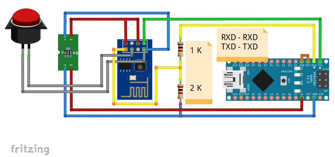
See jumper on RST and GND on Arduino Nano? This is necessary so that arduinka does not interfere with the module's firmware, in the case of connecting the ESP8266 with the help of the Arduino - a mandatory condition.
Also, if you connect to the Arduino - the RX module must go to the Arduinka RX, TX - TX. This is because the converter chip is already connected to the Arduino legs in a cross order.
Also important is the resistive divider consisting of resistors for 1 kΩ and 2 kΩ (can be made of two resistors for 1 kΩ connecting them in series) along the line of the RX module. Because arduino is 5 V logic and module 3.3. It turns out a primitive level converter. It must be, because the legs of the RXD TXD module are not tolerant to 5 V.
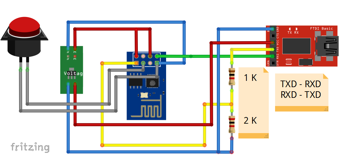
Well, you can do without arduino at all by connecting the ESP8266 via a standard USB-UART converter. In the case of connecting to Arduino, we, in fact, use the regular usb and uart interface converter, bypassing the brains. So why waste time, if you can do without arduino at all? Only in this case, we connect the RXD module to the TXD converter, TXD - RXD.
If you are lazy to bother with the connection, messing with resistors and stabilizers - there are ready-made NodeMcu solutions:
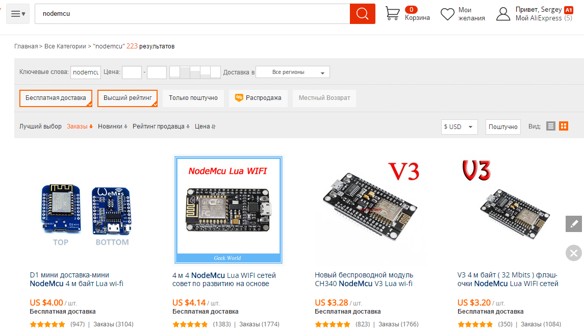
Everything is much simpler, plugged the cable into the computer, installed the drivers and programmed, but do not forget to use the jumper / button on the GPIO0 to switch the module to the firmware mode.
Well, probably everything is with the theory, the article turned out to be perhaps quite a big one, and I will publish the practical part, ala firmware and programming of the module, a little later.
I, on my YouTube channel , opened a whole playlist dedicated to my video on the topic of this Wi-Fi module. The plans were built machine, or boat, on Wi-Fi control, where instead of the remote control will be the usual smart. But so far I have not come to this yet, so these are just plans for the future.
The continuation of this article.
Datasheets for:
ASM1117 3.3 B ;
ESP8266EX (microcontroller that stands in the module) ;
More links:
Russian-speaking community for ESP8266 ;
Schemes painted in the program Fritzing ;
Why many people do not like Arduino ;
All my publications are on geektimes .
By Sergei Delinkinz aka MrPodolkinC.
But how to connect it to arduino? And is it possible to somehow do without Arduino at all? Today this is exactly what will be discussed in this article.
Looking ahead, I will say that there will be a second article, already more practical, on the topic of firmware and programming of the ESP8266 module in the Arduino IDE development environment. But first things first.
')
This video completely duplicates the material presented in the article.
At the moment, there are many variations of this module, here are some of them:
But pinout ESP01, ESP03, ESP12:
* This picture can be viewed in high quality off. site pighixxx.com .
Personally, I like the ESP07 version the most. At least for the fact that there is a metal screen (it protects the chips from external interference, thereby providing a more stable operation), its own ceramic antenna, a connector for an external antenna. It turns out that by connecting an external antenna to it, such as a biquadrate , you can achieve a good range. In addition, there are a lot of input / output ports, the so-called GPIO (General Purpose Input Output - general purpose input-output ports), by analogy with arduino-pins.
Let's go back to our
But, this information will be relevant for most ESP8266 modules and various Arduino boards as well, for example, the most popular Arduino UNO.
A couple of words on ESP01 legs:
Vcc and GND (in the picture above it is 8 and 1) - power supply, Vcc can be supplied to the leg, according to the documentation , from 3 to 3.6 V , and GND - ground (power supply minus). I saw one person connect this module to two AA batteries (the supply voltage in this case was about 2.7 V) and the module was operational. But nevertheless, the developers indicated the voltage range in which the module should work, if you use another, your problems.
Attention! This module is based on 3.3 V logic, and the Arduino basically - 5 V logic. 5 E can easily be damaged by ESP8266, therefore it must be powered separately from the Arduino .
- There is a leg on my arduinka, where 3.3 V is written, why not use it?
Probably you will think. The fact is that the ESP8266 is quite a voracious module, and in peaks it can consume currents up to 200 mA, and almost no arduinka is by default capable of delivering such a current, except the Arduino Due , which has a current of 3.3 V can reach 800 mA, which is enough with a margin, in other cases I advise you to use an additional 3.3 V stabilizer, for example AMS1117 3.3 V. Such shaft in both China and us.
RST 6 leg - is designed to “iron” to reload the module, briefly applying a low logic level to it, the module to reboot. Although I ignored this in the video, I still advise you to “press” this leg with a 10 kΩ resistor to the power supply in order to achieve better stability in the module, otherwise I rebooted from the slightest interference.
The CP_PD 4 leg (or in a different way EN ) serves, again, for the “iron” transfer of the module to the energy-saving mode, in which it consumes a very small current. Well, again - it would not be superfluous to “press” this leg with a 10 kΩ resistor to the positive power supply. In the video, I stupidly short-circuited this leg on Vcc, because there was no such resistor at hand.
Legs RXD0 7 TXD0 2 - hardware UART, which is used for flashing, but nobody forbids using these ports as GPIO (GPIO3 and GPIO1, respectively). For some reason, GPIO3 in the picture is not marked, but in the datasheet it is:
By the way, the “Connect” LED is connected to the TXD0 2 leg, and it is lit at a low logic level on GPIO1, well, or when the module sends something over the UART.
GPIO0 5 - can be not only an I / O port, but also put the module into programming mode. This is done by connecting this port to a low logic level (“pressing” to GND) and applying power to the module. In the video, I do it with a regular button. After flashing, do not forget to pull out the jumper / release the button (it is not necessary to hold the button during flashing, the module switches to programming mode when it is turned on, and remains in it until the reboot).
GPIO2 3 - I / O port.
And one more important moment, each GPIO Wi-Fi module can safely deliver current up to 6 mA , in order not to burn it, be sure to put resistors in series with input / output ports on ... Remember Ohm's law R = U / I = 3.3V / 0.006 A = 550 ohms, that is, 560 ohms . Or ignore it, and then wonder why it does not work.
In ESP01, all GPIOs support PWM, so that we can connect the engine driver to our four GPIOs, that is, GPIO0-3, ala L293 / L298 and steer by two engines, for example, boats, or make RGB Wi-Fi Pribluda. Yes, yes, this module has a lot of things on board, and for unpretentious projects the Arduino
Everything seemed to be explained by pinouts, and here is the wiring diagram of the ESP8266 to the Arduino Nano:
See jumper on RST and GND on Arduino Nano? This is necessary so that arduinka does not interfere with the module's firmware, in the case of connecting the ESP8266 with the help of the Arduino - a mandatory condition.
Also, if you connect to the Arduino - the RX module must go to the Arduinka RX, TX - TX. This is because the converter chip is already connected to the Arduino legs in a cross order.
Also important is the resistive divider consisting of resistors for 1 kΩ and 2 kΩ (can be made of two resistors for 1 kΩ connecting them in series) along the line of the RX module. Because arduino is 5 V logic and module 3.3. It turns out a primitive level converter. It must be, because the legs of the RXD TXD module are not tolerant to 5 V.
Well, you can do without arduino at all by connecting the ESP8266 via a standard USB-UART converter. In the case of connecting to Arduino, we, in fact, use the regular usb and uart interface converter, bypassing the brains. So why waste time, if you can do without arduino at all? Only in this case, we connect the RXD module to the TXD converter, TXD - RXD.
If you are lazy to bother with the connection, messing with resistors and stabilizers - there are ready-made NodeMcu solutions:
Everything is much simpler, plugged the cable into the computer, installed the drivers and programmed, but do not forget to use the jumper / button on the GPIO0 to switch the module to the firmware mode.
Well, probably everything is with the theory, the article turned out to be perhaps quite a big one, and I will publish the practical part, ala firmware and programming of the module, a little later.
I, on my YouTube channel , opened a whole playlist dedicated to my video on the topic of this Wi-Fi module. The plans were built machine, or boat, on Wi-Fi control, where instead of the remote control will be the usual smart. But so far I have not come to this yet, so these are just plans for the future.
The continuation of this article.
Datasheets for:
ASM1117 3.3 B ;
ESP8266EX (microcontroller that stands in the module) ;
More links:
Russian-speaking community for ESP8266 ;
Schemes painted in the program Fritzing ;
Why many people do not like Arduino ;
All my publications are on geektimes .
By Sergei Delinkinz aka MrPodolkinC.
PS
Already on the way, a motherboard based on esp32:

http://www.pighixxx.com/test/2015/12/esp32-pinout/
Which is much cooler than esp8266, so we are soon waiting for a boom, I think, the themes of IoT (Internet of Things) .
http://www.pighixxx.com/test/2015/12/esp32-pinout/
Which is much cooler than esp8266, so we are soon waiting for a boom, I think, the themes of IoT (Internet of Things) .
Source: https://habr.com/ru/post/390593/
All Articles