Control of the brushless motor based on the back EMF signals - understanding the process
When I began to develop a control unit for a brushless motor (motor-wheel), there were many questions about how to compare a real engine with an abstract scheme of three windings and magnets, on which, as a rule, everything explains the principle of control of brushless motors.
When I implemented the control by Hall sensors, I still didn’t really understand what was going on in the engine beyond the abstract three windings and two poles: why is 120 degrees and why the control algorithm is exactly like that.
Everything fell into place when I began to understand the idea of sensorless control of a brushless motor - an understanding of the process taking place in a real piece of hardware helped develop the hardware and understand the control algorithm.
')
Below I will try to paint my way to understanding the principle of control of a brushless DC motor.
For the operation of the brushless motor, it is necessary that the constant magnetic field of the rotor be entrained behind the rotating electromagnetic field of the stator, as in a conventional DC motor.
The rotation of the magnetic field of the stator is carried out by switching the windings using an electronic control unit.
The design of the brushless motor is similar to the design of a synchronous motor, if you connect the brushless motor to a three-phase AC network that meets the electrical parameters of the motor, it will work.
A certain commutation of the windings of the brushless motor allows controlling it from a direct current source. In order to understand how to create a commutation table for a brushless motor, it is necessary to consider the control of a synchronous AC machine.
Synchronous machine
The synchronous machine is controlled from a three-phase AC network. The engine has 3 electric windings offset by 120 electrical degrees.
Having started a three-phase motor in the generator mode, a constant magnetic field will induce EMF to each of the motor windings, the motor windings are evenly distributed, sinusoidal voltage will be induced to each phase and these signals will be shifted between themselves by 1/3 periods (Figure 1). The shape of the EMF varies according to a sinusoidal law, the period of the sinusoid is 2P (360), since we are dealing with electrical quantities (EMF, voltage, current) we call it electrical degrees and we measure the period in them.
When a three-phase voltage is applied to the motor at each moment of time, there will be some current value on each winding.

Figure 1. The type of signal of a three-phase AC source.
Each winding forms a magnetic field vector proportional to the current on the winding. By adding 3 vectors you can get the resultant vector of the magnetic field. Since over time, the current on the motor windings varies sinusoidally, the magnitude of the magnetic field vector of each winding changes, and the resulting total vector changes the angle of rotation, while the magnitude of this vector remains constant.

Figure 2. One electric period of a three-phase motor.
Figure 2 shows one electric period of a three-phase motor; in this period 3 arbitrary moments are designated, in order to build in each of these moments the magnetic field vectors, we postpone this period, 360 electrical degrees, on a circle. We will place 3 motor windings shifted by 120 electrical degrees relative to each other (Figure 3).

Figure 3. Moment 1. The magnetic field vectors of each winding (left) and the resulting magnetic field vector (right).
Along each of the phases there is a magnetic field vector created by the motor winding. The direction of the vector is determined by the direction of the direct current in the winding, if the voltage applied to the winding is positive, then the vector is directed in the opposite direction from the winding, if negative, then along the winding. The magnitude of the vector is proportional to the magnitude of the voltage on the phase at the moment.
To obtain the resulting magnetic field vector, it is necessary to add the vector data according to the law of vector addition.
Similarly, the construction for the second and third moments of time.

Figure 4. Moment 2. The magnetic field vectors of each winding (left) and the resulting magnetic field vector (right).
So, with the passage of time, the resulting vector smoothly changes its direction, in Figure 5 the resulting vectors are depicted and the full rotation of the stator magnetic field is shown in one electric period.

Figure 5. View of the rotating magnetic field formed by the windings on the motor stator.
Behind this vector of the electric magnetic field is the magnetic field of the permanent magnets of the rotor at each moment of time (figure 6).

Figure 6. A permanent magnet (rotor) follows the direction of the magnetic field generated by the stator.
This is how an AC synchronous machine works.
Having a constant current source, it is necessary to independently form one electric period with the change of current directions on the three motor windings. Since the brushless motor has the same design as the synchronous one, it has identical parameters in the generator mode, it is necessary to proceed from Figure 5, which shows the generated rotating magnetic field.
Constant pressure
The DC source has only 2 wires “plus power” and “minus power”, which means that it is possible to apply voltage only to two of the three windings. It is necessary to approximate Figure 5 and select all moments at which it is possible to switch 2 phases out of three.
The number of permutations from the set 3 equals 6, therefore, there are 6 options for connecting the windings.
We draw the possible variants of commutations and select the sequence in which the vector will be turned further step by step until it reaches the end of the period and starts again.
The electric period will be counted from the first vector.

Figure 7. A view of six magnetic field vectors that can be created from a DC source by switching two of the three windings.
Figure 5 shows that when controlling three-phase sinusoidal voltage, there are many vectors that rotate smoothly over time, and when switching with direct current it is possible to get a rotating field of only 6 vectors, that is, switching to the next step should occur every 60 electrical degrees.
The results from figure 7 are summarized in table 1.
Table 1. The resulting sequence of switching motor windings.
The type of the resulting control signal in accordance with Table 1 is shown in Fig. 8. Where -V is the switching on the minus of the power supply (GND), and + V is the switching on the plus of the power supply.

Figure 8. The type of control signals from a DC source for a brushless motor. Yellow - phase W, blue - U, red - V.
However, the real picture of the phases of the engine will be similar to the sinusoidal signal from Figure 1. The signal forms a trapezoidal shape, because at the moments when the motor winding is not connected, the permanent magnets of the rotor induce an emf on it (Figure 9).

Figure 9. View of the signal from the windings of the brushless motor in the operating mode.
On an oscilloscope, it looks like this:

Figure 10. Window view of the oscilloscope when measuring a single motor phase.
Design features
As it was said earlier, after 6 winding switchings, one electric period of 360 electrical degrees is formed.
It is necessary to associate this period with the real angle of rotation of the rotor. Engines with one pair of poles and a three-tooth stator are used extremely rarely, engines have N pairs of poles.
Figure 11 shows engine models with one pair of poles and two pairs of poles.

but. b.
Figure 11. Engine model with one (a) and two (b) pairs of poles.
An engine with two pairs of poles has 6 windings, each winding is a steam room, each group of 3 windings is offset by 120 electrical degrees. In Figure 12b. deferred one period for 6 windings. The windings U1-U2, V1-V2, W1-W2 are interconnected and in the construction are 3 phase output wires. For the sake of simplicity, the connections are not displayed, but you should remember that U1-U2, V1-V2, W1-W2 are the same.
Figure 12, based on the data in Table 1, shows the vectors for one and two pairs of poles.
but. b.
Figure 12. Diagram of magnetic field vectors for a motor with one (a) and two (b) pole pairs.
Figure 13 shows the vectors created by 6 commutations of motor windings with one pair of poles. The rotor consists of permanent magnets, the rotor rotates 360 mechanical degrees in 6 steps.
The figure shows the end positions of the rotor, in the intervals between two adjacent positions the rotor rotates from the previous to the next switched state. When the rotor reaches this end position, the next switch should occur and the rotor will tend to a new target position, so that its magnetic field vector becomes co-directional with the electromagnetic field vector of the stator.

Figure 13. The end positions of the rotor with a six-step commutation of a brushless motor with one pair of poles.
In engines with N pairs of poles, it is necessary to pass N electrical periods for complete mechanical revolution.
A motor with two pairs of poles will have two magnets with S and N poles, and 6 windings (Figure 14). Each group of 3 windings are offset from each other by 120 electrical degrees.
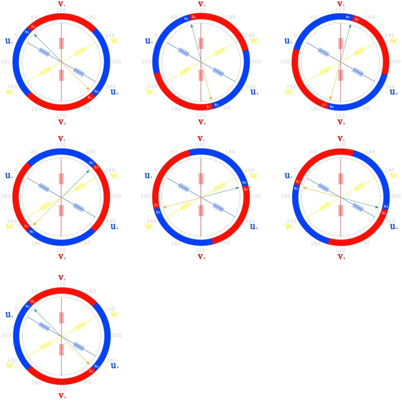
Figure 14. End positions of the rotor with a six-step commutation of a brushless motor with two pairs of poles.
Determining the position of the brushless motor rotor
As it was said earlier for the operation of the engine, it is necessary to connect the voltage to the required stator windings at the right times. It is necessary to supply voltage to the motor windings depending on the position of the rotor, so that the magnetic field of the stator is always ahead of the magnetic field of the rotor. To determine the position of the motor rotor and switching windings using an electronic control unit.
Tracking the rotor position is possible in several ways:
1. According to Hall sensors
2. On the back EMF
As a rule, manufacturers equip the engine with Hall sensors when they are released, so this is the most common control method.
The switching of the windings in accordance with the signals of the reverse electromotive force (EMF) eliminates the sensors built into the motor and, as a sensor, analyzes the free phase of the motor, which will be induced by the back-EMF in a magnetic field.
Control of the brushless motor with Hall sensors
To switch the windings at the right time, you need to track the position of the rotor in electrical degrees. For this, Hall sensors are used.
Since there are 6 states of the magnetic field vector, 3 Hall sensors are needed, which will represent one absolute position sensor with a three-bit output. Hall sensors are also installed as windings, displaced among themselves by 120 electrical degrees. This allows the use of rotor magnets as an acting element of the sensor.

Figure 15. Signals from Hall sensors for one electric motor revolution.
To rotate the motor, it is necessary for the stator magnetic field to be ahead of the rotor magnetic field, the position when the rotor magnetic field vector is co-directed with the stator magnetic field vector is final for this commutation, it is at this moment that the next combination should occur to prevent the rotor from hanging in a stationary position
Let us compare the signals from the Hall sensors with the combination of the phases that need to be switched (Table 2)
Table 2. Comparison of signals from Hall sensors with motor phase switching.
When the motor rotates uniformly, the sensor receives a signal shifted by 1/6 of the period, 60 electrical degrees (Figure 16).

Figure 16. Signal view from Hall sensors.
Control using a feedback signal EMF
There are brushless motors without position sensors. The rotor position is determined by analyzing the EMF signal on the free phase of the engine. At each moment of time, “+” is connected to one of the phases to the other “-” power supply, one of the phases remains free. Rotating, the magnetic field of the rotor induces an emf in the free winding. As it rotates, the voltage on the free phase changes (Figure 17).

Figure 17. Voltage variation in the motor phase.
The signal from the motor winding is divided into 4 points:
1. Winding is connected to 0
2. Winding not connected (free phase)
3. The winding is connected to the supply voltage.
4. Winding is not connected (free phase)
Comparing the signal from the phases with the control signal, it is clear that the moment of transition to the next state can be detected by intersection of the midpoint (half of the supply voltage) with the phase that is not connected at the moment (Figure 18).

Figure 18. Comparison of the control signal with the signal on the phases of the engine.
After detecting the intersection, it is necessary to pause and turn on the next state. According to this figure, the algorithm for switching the winding states is compiled (Table 3).
Table 3. Algorithm for switching motor windings
It is easiest to detect the midpoint intersection with a comparator, the midpoint voltage is applied to one comparator input, and the current phase voltage to the second.

Figure 19. Detection of the midpoint by a comparator.
The comparator is triggered at the time of voltage transition through the midpoint and generates a signal for the microcontroller.
Motor phase signal processing
However, the signal from the phases in the PWM speed control is different in appearance and has a pulsed character (Figure 21); it is impossible to detect an intersection with a midpoint in such a signal.

Figure 20. Type of phase signal for PWM speed control.
Therefore, this signal should be filtered by the RC filter to get the envelope, as well as divided by the requirements of the comparator. As the duty cycle increases, the pitch signal will increase in amplitude (Figure 22).

Figure 21. Diagram of the divider and filter signal from the motor phase.

Figure 22. The signal envelope when changing the duty cycle PWM.
Midpoint pattern

Figure 23. View of the virtual midpoint. Picture taken from avislab.com/
The signals are removed from the phases through current-limiting resistors and are combined; this is the result:

Figure 24. Waveform view of the virtual midpoint voltage.
Because of the PWM, the midpoint voltage is not constant, the signal must also be filtered. The voltage of the midpoint after smoothing will be large enough (in the area of the motor supply voltage), it must be divided by a voltage divider to the value of half the supply voltage.

After the signal passes through the filter, the oscillation is smoothed and an even voltage is obtained with respect to which the intersection of the back EMF can be detected.

Figure 26. Voltage after divider and low pass filter.
The midpoint will change its value depending on the voltage (PWM duty cycle), as well as the signal envelope.

The received signals from the comparators are fed to the microcontroller, which processes them according to the algorithm above.
That's all for now.
When I implemented the control by Hall sensors, I still didn’t really understand what was going on in the engine beyond the abstract three windings and two poles: why is 120 degrees and why the control algorithm is exactly like that.
Everything fell into place when I began to understand the idea of sensorless control of a brushless motor - an understanding of the process taking place in a real piece of hardware helped develop the hardware and understand the control algorithm.
')
Below I will try to paint my way to understanding the principle of control of a brushless DC motor.
For the operation of the brushless motor, it is necessary that the constant magnetic field of the rotor be entrained behind the rotating electromagnetic field of the stator, as in a conventional DC motor.
The rotation of the magnetic field of the stator is carried out by switching the windings using an electronic control unit.
The design of the brushless motor is similar to the design of a synchronous motor, if you connect the brushless motor to a three-phase AC network that meets the electrical parameters of the motor, it will work.
A certain commutation of the windings of the brushless motor allows controlling it from a direct current source. In order to understand how to create a commutation table for a brushless motor, it is necessary to consider the control of a synchronous AC machine.
Synchronous machine
The synchronous machine is controlled from a three-phase AC network. The engine has 3 electric windings offset by 120 electrical degrees.
Having started a three-phase motor in the generator mode, a constant magnetic field will induce EMF to each of the motor windings, the motor windings are evenly distributed, sinusoidal voltage will be induced to each phase and these signals will be shifted between themselves by 1/3 periods (Figure 1). The shape of the EMF varies according to a sinusoidal law, the period of the sinusoid is 2P (360), since we are dealing with electrical quantities (EMF, voltage, current) we call it electrical degrees and we measure the period in them.
When a three-phase voltage is applied to the motor at each moment of time, there will be some current value on each winding.
Figure 1. The type of signal of a three-phase AC source.
Each winding forms a magnetic field vector proportional to the current on the winding. By adding 3 vectors you can get the resultant vector of the magnetic field. Since over time, the current on the motor windings varies sinusoidally, the magnitude of the magnetic field vector of each winding changes, and the resulting total vector changes the angle of rotation, while the magnitude of this vector remains constant.
Figure 2. One electric period of a three-phase motor.
Figure 2 shows one electric period of a three-phase motor; in this period 3 arbitrary moments are designated, in order to build in each of these moments the magnetic field vectors, we postpone this period, 360 electrical degrees, on a circle. We will place 3 motor windings shifted by 120 electrical degrees relative to each other (Figure 3).
Figure 3. Moment 1. The magnetic field vectors of each winding (left) and the resulting magnetic field vector (right).
Along each of the phases there is a magnetic field vector created by the motor winding. The direction of the vector is determined by the direction of the direct current in the winding, if the voltage applied to the winding is positive, then the vector is directed in the opposite direction from the winding, if negative, then along the winding. The magnitude of the vector is proportional to the magnitude of the voltage on the phase at the moment.
To obtain the resulting magnetic field vector, it is necessary to add the vector data according to the law of vector addition.
Similarly, the construction for the second and third moments of time.
Figure 4. Moment 2. The magnetic field vectors of each winding (left) and the resulting magnetic field vector (right).
So, with the passage of time, the resulting vector smoothly changes its direction, in Figure 5 the resulting vectors are depicted and the full rotation of the stator magnetic field is shown in one electric period.
Figure 5. View of the rotating magnetic field formed by the windings on the motor stator.
Behind this vector of the electric magnetic field is the magnetic field of the permanent magnets of the rotor at each moment of time (figure 6).
Figure 6. A permanent magnet (rotor) follows the direction of the magnetic field generated by the stator.
This is how an AC synchronous machine works.
Having a constant current source, it is necessary to independently form one electric period with the change of current directions on the three motor windings. Since the brushless motor has the same design as the synchronous one, it has identical parameters in the generator mode, it is necessary to proceed from Figure 5, which shows the generated rotating magnetic field.
Constant pressure
The DC source has only 2 wires “plus power” and “minus power”, which means that it is possible to apply voltage only to two of the three windings. It is necessary to approximate Figure 5 and select all moments at which it is possible to switch 2 phases out of three.
The number of permutations from the set 3 equals 6, therefore, there are 6 options for connecting the windings.
We draw the possible variants of commutations and select the sequence in which the vector will be turned further step by step until it reaches the end of the period and starts again.
The electric period will be counted from the first vector.
Figure 7. A view of six magnetic field vectors that can be created from a DC source by switching two of the three windings.
Figure 5 shows that when controlling three-phase sinusoidal voltage, there are many vectors that rotate smoothly over time, and when switching with direct current it is possible to get a rotating field of only 6 vectors, that is, switching to the next step should occur every 60 electrical degrees.
The results from figure 7 are summarized in table 1.
Table 1. The resulting sequence of switching motor windings.
| Plus power | Minus power | Winding not connected |
| W | U | V |
| W | V | U |
| U | V | W |
| U | W | V |
| V | W | U |
| V | U | W |
The type of the resulting control signal in accordance with Table 1 is shown in Fig. 8. Where -V is the switching on the minus of the power supply (GND), and + V is the switching on the plus of the power supply.
Figure 8. The type of control signals from a DC source for a brushless motor. Yellow - phase W, blue - U, red - V.
However, the real picture of the phases of the engine will be similar to the sinusoidal signal from Figure 1. The signal forms a trapezoidal shape, because at the moments when the motor winding is not connected, the permanent magnets of the rotor induce an emf on it (Figure 9).
Figure 9. View of the signal from the windings of the brushless motor in the operating mode.
On an oscilloscope, it looks like this:
Figure 10. Window view of the oscilloscope when measuring a single motor phase.
Design features
As it was said earlier, after 6 winding switchings, one electric period of 360 electrical degrees is formed.
It is necessary to associate this period with the real angle of rotation of the rotor. Engines with one pair of poles and a three-tooth stator are used extremely rarely, engines have N pairs of poles.
Figure 11 shows engine models with one pair of poles and two pairs of poles.
but. b.
Figure 11. Engine model with one (a) and two (b) pairs of poles.
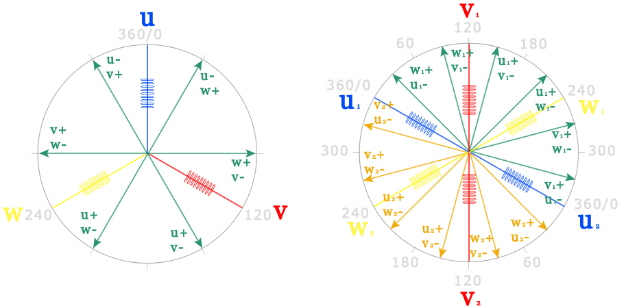
An engine with two pairs of poles has 6 windings, each winding is a steam room, each group of 3 windings is offset by 120 electrical degrees. In Figure 12b. deferred one period for 6 windings. The windings U1-U2, V1-V2, W1-W2 are interconnected and in the construction are 3 phase output wires. For the sake of simplicity, the connections are not displayed, but you should remember that U1-U2, V1-V2, W1-W2 are the same.
Figure 12, based on the data in Table 1, shows the vectors for one and two pairs of poles.
but. b.
Figure 12. Diagram of magnetic field vectors for a motor with one (a) and two (b) pole pairs.
Figure 13 shows the vectors created by 6 commutations of motor windings with one pair of poles. The rotor consists of permanent magnets, the rotor rotates 360 mechanical degrees in 6 steps.
The figure shows the end positions of the rotor, in the intervals between two adjacent positions the rotor rotates from the previous to the next switched state. When the rotor reaches this end position, the next switch should occur and the rotor will tend to a new target position, so that its magnetic field vector becomes co-directional with the electromagnetic field vector of the stator.
Figure 13. The end positions of the rotor with a six-step commutation of a brushless motor with one pair of poles.
In engines with N pairs of poles, it is necessary to pass N electrical periods for complete mechanical revolution.
A motor with two pairs of poles will have two magnets with S and N poles, and 6 windings (Figure 14). Each group of 3 windings are offset from each other by 120 electrical degrees.
Figure 14. End positions of the rotor with a six-step commutation of a brushless motor with two pairs of poles.
Determining the position of the brushless motor rotor
As it was said earlier for the operation of the engine, it is necessary to connect the voltage to the required stator windings at the right times. It is necessary to supply voltage to the motor windings depending on the position of the rotor, so that the magnetic field of the stator is always ahead of the magnetic field of the rotor. To determine the position of the motor rotor and switching windings using an electronic control unit.
Tracking the rotor position is possible in several ways:
1. According to Hall sensors
2. On the back EMF
As a rule, manufacturers equip the engine with Hall sensors when they are released, so this is the most common control method.
The switching of the windings in accordance with the signals of the reverse electromotive force (EMF) eliminates the sensors built into the motor and, as a sensor, analyzes the free phase of the motor, which will be induced by the back-EMF in a magnetic field.
Control of the brushless motor with Hall sensors
To switch the windings at the right time, you need to track the position of the rotor in electrical degrees. For this, Hall sensors are used.
Since there are 6 states of the magnetic field vector, 3 Hall sensors are needed, which will represent one absolute position sensor with a three-bit output. Hall sensors are also installed as windings, displaced among themselves by 120 electrical degrees. This allows the use of rotor magnets as an acting element of the sensor.
Figure 15. Signals from Hall sensors for one electric motor revolution.
To rotate the motor, it is necessary for the stator magnetic field to be ahead of the rotor magnetic field, the position when the rotor magnetic field vector is co-directed with the stator magnetic field vector is final for this commutation, it is at this moment that the next combination should occur to prevent the rotor from hanging in a stationary position
Let us compare the signals from the Hall sensors with the combination of the phases that need to be switched (Table 2)
Table 2. Comparison of signals from Hall sensors with motor phase switching.
| Engine position | HU (1) | HV (2) | HW (3) | U | V | W |
| 0 | 0 | 0 | one | 0 | - | + |
| one | 0 | one | + | - | 0 | |
| one | 0 | 0 | + | 0 | - | |
| one | one | 0 | 0 | + | - | |
| 0 | one | 0 | - | + | 0 | |
| 360 / N | 0 | one | one | - | 0 | + |
When the motor rotates uniformly, the sensor receives a signal shifted by 1/6 of the period, 60 electrical degrees (Figure 16).
Figure 16. Signal view from Hall sensors.
Control using a feedback signal EMF
There are brushless motors without position sensors. The rotor position is determined by analyzing the EMF signal on the free phase of the engine. At each moment of time, “+” is connected to one of the phases to the other “-” power supply, one of the phases remains free. Rotating, the magnetic field of the rotor induces an emf in the free winding. As it rotates, the voltage on the free phase changes (Figure 17).
Figure 17. Voltage variation in the motor phase.
The signal from the motor winding is divided into 4 points:
1. Winding is connected to 0
2. Winding not connected (free phase)
3. The winding is connected to the supply voltage.
4. Winding is not connected (free phase)
Comparing the signal from the phases with the control signal, it is clear that the moment of transition to the next state can be detected by intersection of the midpoint (half of the supply voltage) with the phase that is not connected at the moment (Figure 18).
Figure 18. Comparison of the control signal with the signal on the phases of the engine.
After detecting the intersection, it is necessary to pause and turn on the next state. According to this figure, the algorithm for switching the winding states is compiled (Table 3).
Table 3. Algorithm for switching motor windings
| Current state | U | V | W | Next state |
| one | - | Waiting for midpoint to cross from + to - | + | 2 |
| 2 | Waiting for midpoint intersection from - to + | - | + | 3 |
| 3 | + | - | Waiting for midpoint to cross from + to - | four |
| four | + | Waiting for midpoint intersection from - to + | - | five |
| five | Waiting for midpoint to cross from + to - | + | - | 6 |
| 6 | - | + | Waiting for midpoint intersection from - to + | one |
It is easiest to detect the midpoint intersection with a comparator, the midpoint voltage is applied to one comparator input, and the current phase voltage to the second.
Figure 19. Detection of the midpoint by a comparator.
The comparator is triggered at the time of voltage transition through the midpoint and generates a signal for the microcontroller.
Motor phase signal processing
However, the signal from the phases in the PWM speed control is different in appearance and has a pulsed character (Figure 21); it is impossible to detect an intersection with a midpoint in such a signal.
Figure 20. Type of phase signal for PWM speed control.
Therefore, this signal should be filtered by the RC filter to get the envelope, as well as divided by the requirements of the comparator. As the duty cycle increases, the pitch signal will increase in amplitude (Figure 22).
Figure 21. Diagram of the divider and filter signal from the motor phase.
Figure 22. The signal envelope when changing the duty cycle PWM.
Midpoint pattern
Figure 23. View of the virtual midpoint. Picture taken from avislab.com/
The signals are removed from the phases through current-limiting resistors and are combined; this is the result:
Figure 24. Waveform view of the virtual midpoint voltage.
Because of the PWM, the midpoint voltage is not constant, the signal must also be filtered. The voltage of the midpoint after smoothing will be large enough (in the area of the motor supply voltage), it must be divided by a voltage divider to the value of half the supply voltage.
After the signal passes through the filter, the oscillation is smoothed and an even voltage is obtained with respect to which the intersection of the back EMF can be detected.
Figure 26. Voltage after divider and low pass filter.
The midpoint will change its value depending on the voltage (PWM duty cycle), as well as the signal envelope.
The received signals from the comparators are fed to the microcontroller, which processes them according to the algorithm above.
That's all for now.
Source: https://habr.com/ru/post/390469/
All Articles