Making a simple RC aerial boat
Sometimes on the Internet I see questions from newbies who want to build a quadrocopter from scratch and write firmware to it. I myself am so that in order to practice creating RC models I decided to start with something more simple.
The article in detail for the smallest described the algorithm of the boat, the control panel and the choice of components.
Flying vehicles are great, but difficult. In the air, you can not just turn off the screws, if something goes wrong. Yes, and specific traction is needed very decent, even for airplanes, not to mention multikopter.
')
Platforms like this

( there is a more detailed description).
they know how to move only according to, in most cases, an artificial flat surface, and their control differs greatly.
But on the water, we can swim anywhere, which in the future can give us the opportunity to make an autopilot using GPS. The classic design with the propeller for me is complicated by the shaft exit from the hull - I have no idea how to seal it.
More advantages of air propulsion:
It is necessary that the device could rotate. There are 3 options:
1 joystick + several switches. The task of the console - several times per second to broadcast data on the position of the joystick knob and switches.
First, you need a radio transmitter. The cheapest option is the NRF24L01 +, which costs $ 0.85 .
Secondly, you need a joystick. Another $ 1 .
Several switches - $ 0.12 .
Well, all this is fixed on a piece of PCB for $ 0.13 .
Already counted $ 2.1, but still need MK and power. It's all not so simple.
Looking ahead, I’ll say that ATmega8 or STM8S103F3P6 is quite enough, but since I started this project a long time ago and I had little experience, I put Arduino Pro Mini in the control panel and Arduino Nano (everywhere ATmega32P).
In the remote still needed:
Total plus $ 0.53. Apart from the controller, a pair of capacitors and wires, the cost of the remote control components is $ 2.63.
Everything comes from the engines. What kind of engines you buy, you need to install such an electronic power, and the base (vessel, sled) will require the appropriate capacity. And ideologically, everything else is needed only to rotate the screws with the desired speed.
I bought these motors with propellers
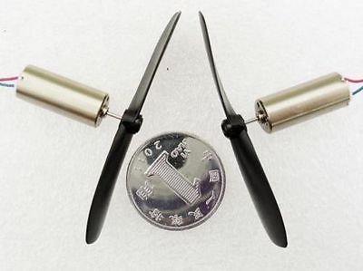
for $ 2.88 per pair .
He took the L293D as a motor driver - another $ 0.35 .
Nutrition. We need as many as three supply voltages:
1 and 2 we will also receive as in the control panel, and for small motors we will put MT3608 for $ 0.86 .
Now the most interesting: gyroscope. The MPU-6050 module costs $ 1.53 . There was a desire to use the accelerometer as well, so that when the joystick knob is moved to the side, the vessel would turn around. But in the end, he rejected this idea: a slight slope in pitch, and the system begins to think that it is accelerating forward or backward. It turned out to be easier to turn the vessel on the spot simply by compensating the movement of the joystick forward / backward.
Add to this $ 0.4 per battery compartment for 2 AA elements and get components for $ 6.4 without a controller and wires.
And again we go from the engines. Each of the two engines driven L293D candig, but can not dig :
To make the code easier to read, write
Now we want to control the speed of rotation of the screws. Of course, we will do this with the help of PWM. I do not know whether it is possible to make such a PWM hardware ... I did it programmatically on interrupts. Let's declare a couple of global variables.
Let the values of these variables <0 mean that it is necessary to turn backwards, values> 0 - forward, and if they are equal to 0, then it is not necessary to turn.
Now, to change the rotational speed of the propeller, we need to do 2 steps:
And you can control the motors by simply calling the functions setMotLeft (int8_t v) and setMotRight (int8_t v).
But we want to control the boat wrong! We want to give commands like "forward / backward" and "right / left"! And let her figure out what kind of propellers for which she has to turn for this. Moreover, I want the boat itself to compensate for the turning action of the wind, the currents and ... crookedly set propellers!
Let's go now from the other side. From the remote control. In the simplest case, the algorithm for its operation is as follows:
Our radio module supports packets up to 32 bytes. In order not to memorize offsets, we will use the record.
On the receiver side, we will declare the exact same entry and
In the setMotRot and setMotForward functions
And move on to the most interesting. To how to convert "turn left at a speed of 5 degrees per second and slightly move forward!" Into "left engine 10% back, right 20% forward!".
About what PID controllers are written quite a lot. I used to rotate only two components:
And for the movement back and forth, the regulator did not use it.
Let's sort on an example:
The code is simplified, in order to focus on important parts, the archive will be the full version.
What are we doing here?
Everything!
This is the whole boat control algorithm!
Complicated? It seems to me no. But, nevertheless, during the tests and adjustments, a whole heap of problems would arise that would lead to numerous derailments if it were an aircraft.
In the described function there are 4 factors:
We adjust these coefficients experimentally, and the response of the boat to the joystick and external sweeping effects will depend on them.
When debugging / configuring, there will be misunderstandings from the series “Why does the boat react to the joystick not in the way I want it to?”. Some points can be debugged by displaying debug information on a PC, but it would be more convenient to understand what is happening right on the spot. At first, I considered 2 options:
The drawbacks of both are clear: the laptop is large and it is inconvenient to carry around with it, and the display of the Nokia 5110 will not allow you to visually display a large number of parameters of the state of the boat.
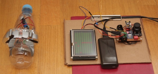
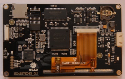
I took something between them: Nextion Enhanced NX4827K043 - Generic 4.3 '' HMI Touch Display . Thanks to the touch screen, you can quickly and conveniently adjust the parameters of the boat on the go. This is a kind of computer consisting of:
Everything in the collection looks like this (clickable):
This computer / display is a black box and is sharpened to interact with a person. Even the existing GPIO is sharpened for connecting buttons and indicators. Their Expansion Board confirms this. So, using the built-in controller as a boat control panel (read the joystick readings, exchange data with the NRF24L01 + radio module) will not work. To interact with the microcontroller there is a UART and ... and that's it.
About how and what you can do with the help of this display you can do, it says a lot + there are videos on Youtube. Look, for example, here it is - everything is clearly shown there. But since this display is more expensive than all the other components of the boat and console combined, I will describe in more detail my impressions of working with it. Perhaps this will help someone to understand whether this option is suitable for him or a laptop / display Nokia 5110 would be preferable. Advantages of Nextion Enhanced NX4827K043:
Disadvantages:
In general, the display creates the impression of a very high-quality product, which is easy and pleasant to work with.
The display can perform two tasks at once:
Made 2 pages (clickable for quality assessment):
Video of the boat test on the floor:
The reaction of the boat to the external unfolding effect at various iDeltaRotMult (integral coefficients):
Demonstration of the influence of parameters on water:
Video on open water could not be photographed. You can take it on faith that he has good handling, and the maximum speed is not very.
Those who have a desire to collect something radio-controlled, I recommend to start with a vessel with two fixed propellers. In my opinion, this is the simplest thing that can be done in this area.
Archive with projects
And finally, to have something to strive for, here is a video of an amazing device:
The article in detail for the smallest described the algorithm of the boat, the control panel and the choice of components.
Why aeroboat?
- Simply;
- Cheap;
- It can move in natural conditions;
- You can train to tweak various control options, including the PID controller.
Flying vehicles are great, but difficult. In the air, you can not just turn off the screws, if something goes wrong. Yes, and specific traction is needed very decent, even for airplanes, not to mention multikopter.
')
Platforms like this
( there is a more detailed description).
they know how to move only according to, in most cases, an artificial flat surface, and their control differs greatly.
But on the water, we can swim anywhere, which in the future can give us the opportunity to make an autopilot using GPS. The classic design with the propeller for me is complicated by the shaft exit from the hull - I have no idea how to seal it.
More advantages of air propulsion:
- It can be put on different platforms: boat, sleigh, piece of foam ...
- It will not catch on the bottom or algae.
It is necessary that the device could rotate. There are 3 options:
- One screw + steering wheel for turns ;
- One screw + turning system ;
- Two rigid screws. Rotate changing their traction - the easiest way. He used it.
Remote control
Operating principle
1 joystick + several switches. The task of the console - several times per second to broadcast data on the position of the joystick knob and switches.
What to do
First, you need a radio transmitter. The cheapest option is the NRF24L01 +, which costs $ 0.85 .
Secondly, you need a joystick. Another $ 1 .
Several switches - $ 0.12 .
Well, all this is fixed on a piece of PCB for $ 0.13 .
Already counted $ 2.1, but still need MK and power. It's all not so simple.
Looking ahead, I’ll say that ATmega8 or STM8S103F3P6 is quite enough, but since I started this project a long time ago and I had little experience, I put Arduino Pro Mini in the control panel and Arduino Nano (everywhere ATmega32P).
In the remote still needed:
- Power converter 0.9 - 5 V -> 5 V to power the Arduino for $ 0.35 (USB connector, together with a piece of board, can be broken off for compactness);
- The 3.3 V AMS1117-3.3 stabilizer for powering the radio module, they cost $ 0.03 per unit ;
- Battery compartment for one finger battery for $ 0.15 ;
Total plus $ 0.53. Apart from the controller, a pair of capacitors and wires, the cost of the remote control components is $ 2.63.
The filling of the radio-controlled model
Components
Everything comes from the engines. What kind of engines you buy, you need to install such an electronic power, and the base (vessel, sled) will require the appropriate capacity. And ideologically, everything else is needed only to rotate the screws with the desired speed.
I bought these motors with propellers
for $ 2.88 per pair .
He took the L293D as a motor driver - another $ 0.35 .
And then a lot of problems
For L293D, the switched voltage must not be lower than the logic supply voltage. And these motors very much subsided the voltage, as a result of which the current from the logic power flowed into the motors and the logic power along with the power of the microcontroller also dropped to the point that the MC was turned off.
Nutrition. We need as many as three supply voltages:
- 5 V for all electronics except radio;
- 3.3 V for the radio module;
- for motors as they need (my 4.2 V).
1 and 2 we will also receive as in the control panel, and for small motors we will put MT3608 for $ 0.86 .
Now the most interesting: gyroscope. The MPU-6050 module costs $ 1.53 . There was a desire to use the accelerometer as well, so that when the joystick knob is moved to the side, the vessel would turn around. But in the end, he rejected this idea: a slight slope in pitch, and the system begins to think that it is accelerating forward or backward. It turned out to be easier to turn the vessel on the spot simply by compensating the movement of the joystick forward / backward.
Add to this $ 0.4 per battery compartment for 2 AA elements and get components for $ 6.4 without a controller and wires.
Program
And again we go from the engines. Each of the two engines driven L293D can
- Twist forward;
- Twist back;
- Do not twist.
To make the code easier to read, write
6 functions
inline void motLeftStop(){ PORTD &= ~(1 << MOT_LEFT_PLUS); PORTD &= ~(1 << MOT_LEFT_MINUS); } inline void motLeftForward(){ PORTD |= 1 << MOT_LEFT_PLUS; PORTD &= ~(1 << MOT_LEFT_MINUS); } inline void motLeftBackward(){ PORTD &= ~(1 << MOT_LEFT_PLUS); PORTD |= 1 << MOT_LEFT_MINUS; } inline void motRightStop(){ PORTD &= ~(1 << MOT_RIGHT_PLUS); PORTD &= ~(1 << MOT_RIGHT_MINUS); } inline void motRightForward(){ PORTD |= 1 << MOT_RIGHT_PLUS; PORTD &= ~(1 << MOT_RIGHT_MINUS); } inline void motRightBackward(){ PORTD &= ~(1 << MOT_RIGHT_PLUS); PORTD |= 1 << MOT_RIGHT_MINUS; } Now we want to control the speed of rotation of the screws. Of course, we will do this with the help of PWM. I do not know whether it is possible to make such a PWM hardware ... I did it programmatically on interrupts. Let's declare a couple of global variables.
int8_t motLeft = 0, motRight = 0; // -127..+127 Let the values of these variables <0 mean that it is necessary to turn backwards, values> 0 - forward, and if they are equal to 0, then it is not necessary to turn.
Write the timer interrupt handlers
ISR(TIMER2_OVF_vect) { if(motLeft > 0) motLeftForward(); else if(motLeft < 0) motLeftBackward(); if(motRight > 0) motRightForward(); else if(motRight < 0) motRightBackward(); } ISR(TIMER2_COMPA_vect) { motLeftStop(); } ISR(TIMER2_COMPB_vect) { motRightStop(); } Now, to change the rotational speed of the propeller, we need to do 2 steps:
- Write a positive, negative or zero value in motLeft / motRight (module is not important);
- Write the “rotation speed” in OCR2A / OCR2B.
Let's write for this another couple of functions.
Strings
it is necessary that the boat does not spend energy trying to turn the screws and writing a value less than 5 in OCR2x (they still do not spin).
void setMotLeft(int8_t v){ // -127..+127 if(abs(v) < 5) v = 0; motLeft = v; OCR2A = abs(v) * 2; } void setMotRight(int8_t v){ // -127..+127 if(abs(v) < 5) v = 0; motRight = v; OCR2B = abs(v) * 2; } Strings
if(abs(v) < 5) v = 0; it is necessary that the boat does not spend energy trying to turn the screws and writing a value less than 5 in OCR2x (they still do not spin).
It now remains to configure the pins MK and timer
void motInit(){ DDRD |= (1 << MOT_LEFT_PLUS) | (1 << MOT_LEFT_MINUS) | (1 << MOT_RIGHT_PLUS) | (1 << MOT_RIGHT_MINUS); //TCCR2B |= (1 << CS22)|(1 << CS21)|(1 << CS20); // set up timer with prescaler = 1024. 16 //TCCR2B |= (1 << CS22)|(0 << CS21)|(0 << CS20); // set up timer with prescaler = 64. 1 TCCR2B |= (0 << CS22)|(1 << CS21)|(0 << CS20); // set up timer with prescaler = 8. 128 //TCCR2B |= (0 << CS22)|(0 << CS21)|(1 << CS20); // set up timer with prescaler = 1. 16 TIMSK2 |= (1 << TOIE2)|(1 << OCIE2A)|(1 << OCIE2B); // enable overflow interrupt TCCR2A &= ~(3); // set WGM20 = 0, WGM21 = 0 TCCR2B &= ~(1 << 3); // set WGM22 = 0 setMotLeft(0); setMotRight(0); sei(); } And you can control the motors by simply calling the functions setMotLeft (int8_t v) and setMotRight (int8_t v).
But we want to control the boat wrong! We want to give commands like "forward / backward" and "right / left"! And let her figure out what kind of propellers for which she has to turn for this. Moreover, I want the boat itself to compensate for the turning action of the wind, the currents and ... crookedly set propellers!
Let's go now from the other side. From the remote control. In the simplest case, the algorithm for its operation is as follows:
- When you turn on the power, remember the starting position of the joystick;
- In the cycle, read the position of the joystick, subtract the zero position from it and send the data to the boat.
Our radio module supports packets up to 32 bytes. In order not to memorize offsets, we will use the record.
struct ControlStatus{ int16_t x,y; } controlStatus; In the following way
uint8_t packet[MAX_BUFF]; memset(packet, 0, MAX_BUFF); controlStatus.x = (int16_t)analogRead(1) - x0; controlStatus.y = (int16_t)analogRead(0) - y0; memcpy(packet, &controlStatus, sizeof(controlStatus)); Mirf.send(packet); while(Mirf.isSending()){;}; On the receiver side, we will declare the exact same entry and
we will fill it
while (Mirf.dataReady()) { uint8_t data[MAX_BUFF]; Mirf.getData(data); memcpy(&controlStatus, data, sizeof(controlStatus)); setMotRot(-controlStatus.x); setMotForward(controlStatus.y); } In the setMotRot and setMotForward functions
write the values in the global variables motRot and motForward
void setMotRot(int16_t v){ if(abs(v)<10) v = 0; motRot = (int32_t)v; } void setMotForward(int16_t v){ if(abs(v)<10) v = 0; motForward = (int32_t)v; } And move on to the most interesting. To how to convert "turn left at a speed of 5 degrees per second and slightly move forward!" Into "left engine 10% back, right 20% forward!".
About what PID controllers are written quite a lot. I used to rotate only two components:
- Proportional;
- Integral.
And for the movement back and forth, the regulator did not use it.
Let's sort on an example:
int32_t iDeltaRot = 0; void motTick(){ int32_t rot = getRotAvg(); // int32_t deltaRot = rot - motRot * rotMaxSpeed / 512; iDeltaRot += deltaRot; int32_t motRight = (int32_t)motForward * forwardMult - deltaRot * rotMult - iDeltaRot * iDeltaRotMult, motLeft = (int32_t)motForward * forwardMult + deltaRot * rotMult + iDeltaRot * iDeltaRotMult; int32_t motMax = max(abs(motRight), abs(motLeft)); if(motMax > 127){ motRight = (int32_t)motRight * 127 / motMax; motLeft = (int32_t)motLeft * 127 / motMax; } setMotRight(motRight); setMotLeft(motLeft); } The code is simplified, in order to focus on important parts, the archive will be the full version.
What are we doing here?
- Calculate the difference between the real speed of rotation of the boat (rot) and the desired (motRot * rotMaxSpeed);
- Calculate the desired rotation speed of the screws motRight and motLeft;
- If the desired rotational speeds exceed the maximum possible ones, reduce them keeping the ratio between them;
- Call the setMotRight / setMotLeft already familiar to us.
Everything!
This is the whole boat control algorithm!
Complicated? It seems to me no. But, nevertheless, during the tests and adjustments, a whole heap of problems would arise that would lead to numerous derailments if it were an aircraft.
In the described function there are 4 factors:
- forwardMult - sensitivity to the movement of the joystick forward / backward;
- rotMaxSpeed - the desired rotation speed when the joystick is tilted all the way to the right / left;
- rotMult - the coefficient of the proportional component (how much the deviation of the current rotational speed from the desired one affects the rotation);
- iDeltaRotMult is the coefficient of the integral component (how much does the deviation of the current angle of rotation from the desired effect on the rotation).
We adjust these coefficients experimentally, and the response of the boat to the joystick and external sweeping effects will depend on them.
Status indication
When debugging / configuring, there will be misunderstandings from the series “Why does the boat react to the joystick not in the way I want it to?”. Some points can be debugged by displaying debug information on a PC, but it would be more convenient to understand what is happening right on the spot. At first, I considered 2 options:
- A laptop;
- Display Nokia 5110
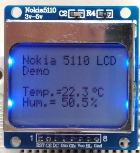
The drawbacks of both are clear: the laptop is large and it is inconvenient to carry around with it, and the display of the Nokia 5110 will not allow you to visually display a large number of parameters of the state of the boat.
I took something between them: Nextion Enhanced NX4827K043 - Generic 4.3 '' HMI Touch Display . Thanks to the touch screen, you can quickly and conveniently adjust the parameters of the boat on the go. This is a kind of computer consisting of:
- Microcontroller GD32F103R8T6;
- Winbond W9864G6KH-6 SDRAM (8 MB);
- Winbond W25Q256FVFG flash memory (32 MB, 100,000 rewrite cycles, which is quite pleasing);
- FPGA Altera MAX II EPM570T144C5N.
Everything in the collection looks like this (clickable):
This computer / display is a black box and is sharpened to interact with a person. Even the existing GPIO is sharpened for connecting buttons and indicators. Their Expansion Board confirms this. So, using the built-in controller as a boat control panel (read the joystick readings, exchange data with the NRF24L01 + radio module) will not work. To interact with the microcontroller there is a UART and ... and that's it.
About how and what you can do with the help of this display you can do, it says a lot + there are videos on Youtube. Look, for example, here it is - everything is clearly shown there. But since this display is more expensive than all the other components of the boat and console combined, I will describe in more detail my impressions of working with it. Perhaps this will help someone to understand whether this option is suitable for him or a laptop / display Nokia 5110 would be preferable. Advantages of Nextion Enhanced NX4827K043:
- Very easy to use. There is simple documentation, examples, videos on Youtube, ... For a couple of hours, you can figure it out from scratch. Almost everything you need to know about him is on two pages: the wiki page and the Instruction Set
- Very fast development. Visual editor like Visual Studio (only easier). Threw components and everything works.
- High quality components. Same flash memory for 100k rewrite cycles.
- A debugger that can simulate a display using a PC and communicate with your MC via a COM port. Allows you to fully develop the device, debug and buy the display, only if everything is fine.Although there is a problem with himWith frequent updates of the display readings, the debugger does not even have time on a very good computer. The piece of iron works much faster. However, if in your case you manage to do everything in the debugger, then when transferring to iron, the situation should not get worse.
- Resistive sensor. You can create quite small controls and poke them with a fingernail or any stylus.
Disadvantages:
- Price. $ 50 is still a lot for the 4.3 '' display.
- There are few existing components, there is little component configuration, how to create your own is not clear. This is partially offset by the primitive drawing functions (lines, rectangles, circles, ...).
- The standard component Gauge flickers when upgrading.
- No (at least I did not find) transparency.
- Power requirements: 4.75-7 V and average current 250 mA. When voltage drops, the display flashes.
- Only UART. Could make communication with him even on SPI and I²C.
- GPIO output only under a loop (no comb 2.54 mm), no ADC.
In general, the display creates the impression of a very high-quality product, which is easy and pleasant to work with.
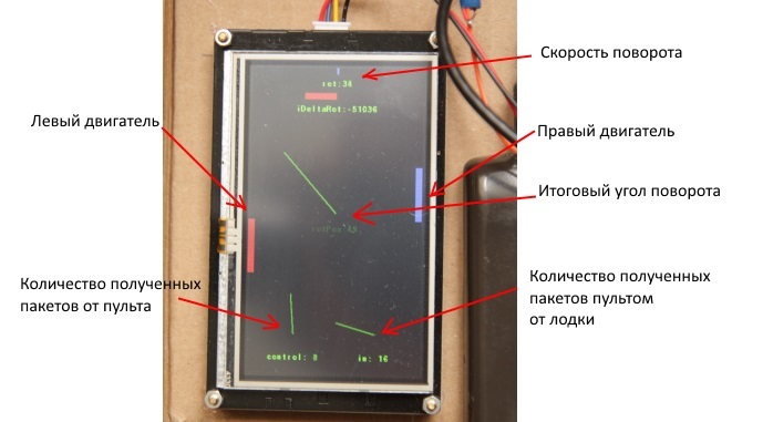
The display can perform two tasks at once:
- Status indication. I am primarily interested in:
- "Speed of rotation" screws;
- The value of the variable iDeltaRot - how much the desired angle of rotation is different from the desired one;
- Boat rotation speed;
- Angle of rotation of the boat;
- The frequency of receiving packets from the remote;
- The frequency of calls to the motTick function.
- Setting parameters, namely the above described forwardMult, rotMaxSpeed, rotMult, iDeltaRotMult.
Made 2 pages (clickable for quality assessment):
- Indications:
- Parameter Settings:
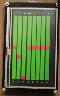
The first 4 columns from left to right are: forwardMult, rotMult, iDeltaRotMult, rotMaxSpeed.
Video of the boat test on the floor:
The reaction of the boat to the external unfolding effect at various iDeltaRotMult (integral coefficients):
Demonstration of the influence of parameters on water:
Video on open water could not be photographed. You can take it on faith that he has good handling, and the maximum speed is not very.
Specifications
- Traction 9 g;
- Weight 115 g, of which batteries weigh 52g;
- The maximum acceleration is obtained at 0.77 m / s ^ 2. To human 5 km / h, if there was no water resistance, the boat would accelerate in 1.8 s;
- The cost of the components is about $ 15 if you use Arduino Nano in both the remote and in the boat (without the display and batteries).
Conclusion
Those who have a desire to collect something radio-controlled, I recommend to start with a vessel with two fixed propellers. In my opinion, this is the simplest thing that can be done in this area.
Archive with projects
And finally, to have something to strive for, here is a video of an amazing device:
Source: https://habr.com/ru/post/390429/
All Articles