DVB Stick Radio for $ 8 - Learn SDR with GNURadio
Every day we use a variety of radio devices. However, we rarely understand how they work. The era of radio amateurs actually passed, leaving in the past fans to solder a DV receiver or CB with their own hands. Yes, and in the methods of coding technique has gone far ahead. We often hear discourses about hacking smart homes on radio protocols, the unreliability of radio communications, etc. But how many of you have tried, for example, to overhear the Z-Wave network of your neighbor's smart home and, all the more, to control it? How big is this threat to you?
Fortunately, very convenient means have become available these days to work with the radio, namely SDR.
SDR (Software Defined Radio) allows you to programmatically rebuild the receiver and transmitter to work at different frequencies from 20 to 2000 MHz, and then perform signal processing on a computer using digital methods. This significantly distinguishes SDR from analogue circuits of radio receivers and transmitters, making it easy to change the algorithm for processing the received signal.
')

There are many different programs for processing radio signals. I studied the most popular of them GNURadio. This package allows you to build processing from different blocks, connecting them with each other in the format of stream processing (pipe). Each next block receives data from one or several previous ones, and the output is transferred to other blocks.
Under the cut, I will talk about the basics of SDR and GNURadio and how to make an AM / FM receiver, a Chinese controlled outlet, satellite telemetry and everything that pleases, for 8 bucks.
Home radio allows you to listen to many stations in different bands. However, there is still a lot of other things on the air! And you do not need to connect anywhere to get this data - this data flies past you on the air every second. We can say, every day we are pierced by gigabytes of interesting data. It is enough to accept and detect them. Are you curious? Personally, I am very.
Using the SDR transmitter, you can also create radio transmitters yourself. For example, make a baby monitor. Or control 433 MHz smart home appliances or even Z-Wave.
However, I want to immediately warn: study the legislation and the decisions of the SCR on the frequency bands you use and do not violate them!
Personally, I came to the SDR, for many years engaged in the development of Z-Wave devices. As I already wrote , the developers do not give access to the radio receiver. Therefore, I always wondered if I could intercept the signal of the neighboring Z-Wave network or make fun of the neighbor, including its devices (not all Z-Wave devices have encryption yet, so this is still possible). After all, my Z-Wave network is just as vulnerable. It turned out that this is not so simple (I have not yet been able to do this with GNURadio, without using ready-made tools), but I hope I will come to this and even write in a future article. In the meantime (in the next article) we will be content to receive commands from the console to the socket from the Chinese set at 433 MHz, as well as sending on / off commands. Here the protocol was at times easier.
But back to the basics.
Let's start with a little insight into the theory. I assume that the reader remembers trigonometry and can independently google about the Fourier transform or read the references that I provide.
For data transmission over the radio using modulation. Modulation is a way to convert a low-frequency signal to a high-frequency one, transferring information to the carrier region, so that later, after transmission, it can be demodulated, i.e. convert back to low frequency. High frequency while called carrier, because it is this frequency (or rather the range of frequencies around the carrier frequency) that will transfer data during transmission.
For example, if we send commands between Z-Wave devices, the carrier frequency will be 869 MHz.
It is clear that even modern computers cannot afford to digitize the signal at such a frequency - for reliable digitization, it will be necessary to run the ADC approximately every 8,700,000 times per second (if we consider 10 samples per period to be a sufficient time step). However, this makes no sense, because we are interested in a very small frequency band of 869 MHz ± 200 kHz, i.e. less than 0.5 MHz wide.
Recall that when multiplying on
on  , the result can be represented as a sum of two sinusoids with frequencies
  and
and  . If a
  chosen close to the carrier, then discarding the last term (using a low-pass filter - because the last term contains twice the carrier frequency), we get the opportunity to investigate the low-frequency signal from -200 kHz to +200 kHz, which even a microcontroller can do (for example, Z -Wave SD3502 or various TI or SiLabs chips). Those who remember the device of old radios, see here the analogy with the local oscillator.
The SDR's job is to generate a synthetic signal at the desired frequency, multiply it with the filtered input signal from the antenna, pass the frequency through the low-pass filter, remove the high-frequency component, feed into the ADC and then transfer to processing as is. Similarly, the transfer occurs - after the DAC, the signal is multiplied with the high-frequency signal and radiated by the antenna.
The block diagram of the SDR receiver shows how the input signal from the antenna is converted.
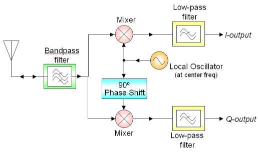
After pre-filtering and multiplying the input signal by a synthetic signal (and shifted by 1/4 of the phase, which corresponds to the transition from to  ), both of the resulting signals are amplified, pass a low-pass filter (to remove the imposition of high-frequency components during sampling) and digitized. Digitization inside the SDR receiver is usually done at 50 MHz (usually they write about 50 MSPS, Million Samples Per Second, millions of samples per second), after which another filter is used that converts the stream into the required number of samples per second (usually no more than 2-5 MSPS). This last process is called decimation. The received signals are called I and Q, respectively.
These two quantities, I and Q, make it possible to go from a real signal to a complex representation. where
where  in the general case, a complex number, the imaginary part of which speaks of a phase, and the real one of amplitude. In this form, mathematics looks much easier. For example, the specified frequency shift in such a representation is made by simple multiplication by
  .
.
It is important to remember that a physically significant signal is the real part of our complex presentation Re. However, the complex form allows you to select the amplitude and phase.
Specialized radio equipment is expensive. However, we were lucky - most modern receivers and transmitters are exactly SDR, i.e. programmatically adjusted to the desired frequency. And some of the available cheap receivers even give access to data from the ADC. The most popular examples of such SDR receivers are DVB tuners. The most popular and convenient are RTL-SDR, based on Realtek RTL2832U chips. On AliExpress, a variety of them are presented at an average price of $ 8 (look according to RTL2832U and R820T or E4000).
Here, for example, two dongles from the entire selection that I bought for tests.
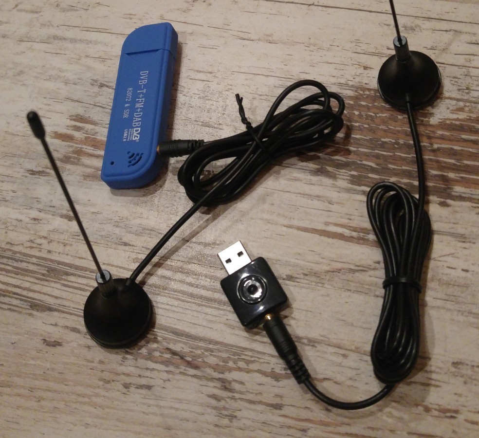
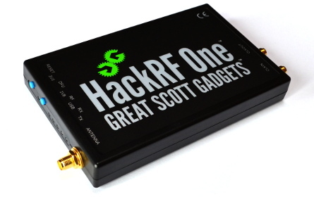
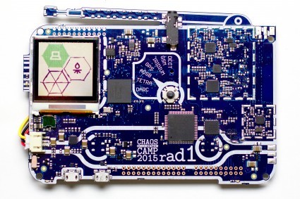
It is also worth noting more professional, but still available pieces of iron for games with SDR: HackRF One and Rad1o badge , made at CCC 2015. These pieces of iron allow you not only to receive, but also to radiate in a wide frequency range.
So, having received a sequence of I and Q values, we can proceed to digital signal processing.
The GNURadio package includes not only a set of program blocks for signal processing, but also a graphic designer that allows you to draw a signal processing flowchart that is converted upon launch into a ready-made program code for the handler. This is a very convenient way to process data, because it allows you to follow exclusively the meaning of processing and not pay attention to the details of the program code.
What actions allow you to do blocks in GNURadio? These are basic mathematical operations on a signal (addition / subtraction of signals, multiplication), as well as more complex ones, such as the same decimation, interpolation, and various filters.
Most filters convert the input signal, minimizing it with special functions. However, some filters work not with the signal itself, but with its spectrum. For example, a low-pass filter works according to the principle of signal spectrum conversion, reducing high frequencies, after which the resulting spectrum is converted back into a signal (although it is more often minimized). In general, the spectrum plays a very important role in digital signal processing.
Perhaps the most important characteristics when building a signal flowchart are sample rate (how many samples per second we get), measured in MSPS and signal spectrum. They are strongly connected with each other.
As is known from mathematics, any periodic function can be represented as a Fourier transform, and any periodic function can be expanded into a Fourier series with an infinite number of terms. If we are talking about a sequence of discrete values, i.e. the values are important to us only at certain points in time, then the Fourier series will consist of a finite number of terms equal to the number of initial values:

Such a decomposition is called the Discrete Fourier Transform or DFT.
It is seen that the highest cyclic frequency, which is involved in the signal spectrum, is . After all, sample rate is the number of values
  per second (N pieces), i.e. time step is
  seconds and the highest frequency
  Hz For example, if the sample rate is 2,000,000, then the maximum frequency will be 2 MHz. Now it becomes clear that to analyze the band from -200 to 200 kHz, we need to have a sample rate of at least 400,000.
There is another interesting and non-obvious DFT property: the spectrum of a discrete function is periodic, i.e. . Mathematically, this is easily proven. Why is this important to us? When studying the spectrum in the window that displays the spectrum in GNURadio, you will often think about what’s right and left there (after all, there should be visible spectra of neighboring radio stations, intuition tells us). However, this is not the case; outside the window, the spectrum is repeated in the same way again, and again. But what about the neighboring frequencies and radio stations? Where did they go? Information about them was lost at the moment when we digitized the signal around the carrier with a certain sample rate.
Now, I hope, it has become clear from what considerations it is necessary to choose the sample rate: the spectrum of the studied signal should fit into the spectral width of the window, corresponding to the selected sample rate. With most SDRs, the sample rate cannot exceed 2-5 MSPS.
Very good on the Fourier transform, DFT and FFT (Fast Fourier Transform) is written here .
So, we figured out that to calculate the signal spectrum using the DFT, the values are collected in a sequence of N pieces. Each subsequent value is added, displacing the oldest (FIFO).
So, I have a Chinese stick based on RTL2832U and R820T2. The first thing we try to do is make an FM receiver. Frequency modulation is not the easiest and I first wanted to demonstrate everything with an example of amplitude modulation. But alas, in the range> 20 MHz there are no stations with AM modulation.
Open GNURadio Companion and in the Options block, immediately select the WX GUI (learn the interface provided by QT yourself). To do this, double click on the block and change the property.
Add an osmocom source block and immediately change the value of Ch0: Frequency to freq. GNURadio is written in Python, and python expressions can be substituted into any numeric fields. Watch the type of fields carefully - if this is a float, then the result should be a real number, if int, then an integer. Notice that the sample rate is already associated with the variable samp_rate, which is defined in a separate block. Change samp_rate to 2e6, i.e. we will set our signal band to 2 MHz.
The variable freq will be set by slider. To do this, add the WX GUI Slider block, change its ID to freq and set Default, Minimum and Maximum to 100e6, 50e6 and 150e6, respectively (note that the record 100e6 is a valid number of nbgf float in Python). When the slider is moving, the freq value will change from 50,000,000 to 150,000,000 in increments of 1,000,000 (100 divisions, see the Num Steps field).
Now add the WX GUI FTT Sink block (graphical display of DFT results). Connect the valve in this block with the valve out of the osmocom source block. With this we indicated GNURadio that the output of one block must be passed to the input of another block.

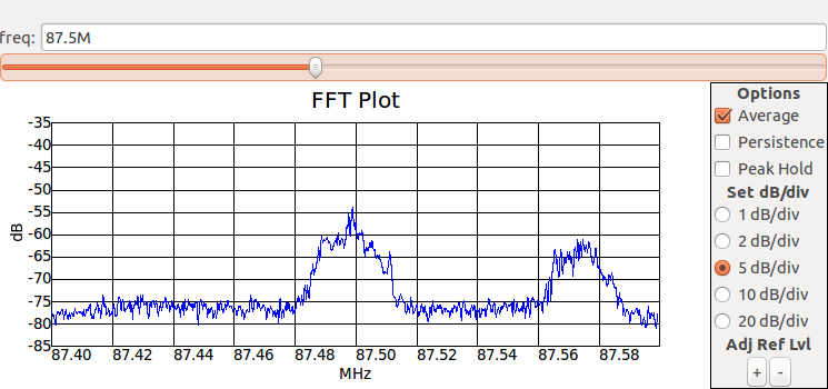
Run our project. In the window that appears, you can see the spectrum with frequencies from -1 MHz to 1 MHz (as we ordered, the range is 2e6 MHz in accordance with samp_rate). But we are looking at the range of 100 MHz, and not -1 - +1 MHz! The thing is that the frequency multiplication has already happened in the SDR, and the signal coming from the SDR does not really have information about the original frequency. Therefore, for convenience, in the WX GUI FTT Sink block, in the Baseband Frequency field, also specify the value of the freq variable. After restarting the frequency scale will look more visible.
So, move the slider in the range of 60–110 MHz and watch the spectrum: you see a lot of FM stations. Also look at how much the reception changes as your arm approaches the antenna. The standard antenna is designed for a range of approximately 800 MHz, and your body changes the effective length of the antenna, making reception better.
And now I suggest listening to your favorite station. FM demodulation is not very simple in mathematics, so GNURadio even has a ready-made FM Demod block. He needs to specify the channel width and decimation for the output audio signal. The latter should be equal to the ratio of the current sample rate to the one that the audio signal should have (48 kHz). Connect the output of this unit to Audio Sink . For convenience, we will add another variable audio_samp_rate = 48000 (this is int!) For the sound card's bit rate, and decimation int (samp_rate / audio_samp_rate). But if such a project is launched and tuned in to one of the stations in your city, then the station’s broadcast will be heavily jammed with noise. And this is understandable, we forgot to select one station from the entire range.
Add one more Low Pass Filter block between the osmocom source and FM Demod blocks. This is a low pass filter. We configure it to cut everything beyond 100 kHz with a 100 kHz transition (you can then select better parameters). Now the sound will be much cleaner. Also, if the volume is low, then you can add Multiply Const before Audio Sink to increase the amplitude of the output audio signal.

From one block you can transfer data not only to one, but also to several blocks.
When designing flowcharts in GNURadio, it is often convenient to add an FFT Sink window and other visualization tools. However, a large number of them pretty much load the processor. You can, of course, delete such blocks when they are no longer needed. But in GNURadio there is a convenient opportunity to turn off a block without removing it. This can be done from the context menu or by pressing the D [isable] and E [nable] shortcut keys.
When analyzing a signal from electronic devices, it is often necessary to press buttons on them to receive a radio sequence. But you can write a sequence to a file once, then play it and work out a flowchart. To record, use the File Sink block, and to play the File Source . There is a pitfall: when playing from a file, GNURadio does not know anything about the speed with which it is necessary to “feed” data to the rest of the block, and will try to work at maximum speed while loading the processor. To limit the reading speed, we need to add a special block Throttle , indicating the desired sample rate.
If you need to shift the spectrum to the right or left by some value (for example, to apply the Low Pass filter afterwards), you can multiply the signal by a sine wave. To do this, use the Signal Source block and multiply them with Multiply . Exactly what is done in the SDR receiver. For example, you can send a signal in two sequences of blocks. In one shift to one side frequency, in the second to another side frequency. Then both filter the low pass filter and compare the two signals. This is what is done when detecting frequency shift keying.
By the way, if you make the slider change the frequency of the Signal Source, then in practice you will see how the signal spectrum shifted beyond the right edge appears in the opposite direction, and vice versa.
When studying the spectra of signals with some RTL-SDR, you will encounter a constant peak exactly in the middle of the spectrum. Moreover, this peak does not move during frequency tuning, always remaining in the middle. This phenomenon is called DC spike . Obviously, this frequency (0 Hz) corresponds to a constant. It is connected with the fact that in the receiver before the ADC there is a small constant component. In GNURadio, the osmocom source and RTL-SDR source blocks have a DC Offset Mode check box, which allows you to remove this component.
In addition to writing to a file, GNURadio has blocks for transmitting sockets to UDP / TCP and receiving data from them. For example, you can even make a radio -> UDP broadcast broadcast.
I want to try to transfer data, but have not yet acquired Hack RF One or equivalent? No problem. You can practice using Audio Sink with Audio Source . For example, you can learn how to transmit data through ultrasonic waves using a microphone and speakers. Here is an example of such a project: www.anfractuosity.com/projects/ultrasound-via-a-laptop
gnuradio.org/redmine/projects/gnuradio/wiki
greatscottgadgets.com/hackrf
habrahabr.ru/post/204310
Fortunately, very convenient means have become available these days to work with the radio, namely SDR.
SDR (Software Defined Radio) allows you to programmatically rebuild the receiver and transmitter to work at different frequencies from 20 to 2000 MHz, and then perform signal processing on a computer using digital methods. This significantly distinguishes SDR from analogue circuits of radio receivers and transmitters, making it easy to change the algorithm for processing the received signal.
')
There are many different programs for processing radio signals. I studied the most popular of them GNURadio. This package allows you to build processing from different blocks, connecting them with each other in the format of stream processing (pipe). Each next block receives data from one or several previous ones, and the output is transferred to other blocks.
Under the cut, I will talk about the basics of SDR and GNURadio and how to make an AM / FM receiver, a Chinese controlled outlet, satellite telemetry and everything that pleases, for 8 bucks.
Why do we need SDR?
Home radio allows you to listen to many stations in different bands. However, there is still a lot of other things on the air! And you do not need to connect anywhere to get this data - this data flies past you on the air every second. We can say, every day we are pierced by gigabytes of interesting data. It is enough to accept and detect them. Are you curious? Personally, I am very.
Using the SDR transmitter, you can also create radio transmitters yourself. For example, make a baby monitor. Or control 433 MHz smart home appliances or even Z-Wave.
However, I want to immediately warn: study the legislation and the decisions of the SCR on the frequency bands you use and do not violate them!
Personally, I came to the SDR, for many years engaged in the development of Z-Wave devices. As I already wrote , the developers do not give access to the radio receiver. Therefore, I always wondered if I could intercept the signal of the neighboring Z-Wave network or make fun of the neighbor, including its devices (not all Z-Wave devices have encryption yet, so this is still possible). After all, my Z-Wave network is just as vulnerable. It turned out that this is not so simple (I have not yet been able to do this with GNURadio, without using ready-made tools), but I hope I will come to this and even write in a future article. In the meantime (in the next article) we will be content to receive commands from the console to the socket from the Chinese set at 433 MHz, as well as sending on / off commands. Here the protocol was at times easier.
But back to the basics.
Materiel
Let's start with a little insight into the theory. I assume that the reader remembers trigonometry and can independently google about the Fourier transform or read the references that I provide.
For data transmission over the radio using modulation. Modulation is a way to convert a low-frequency signal to a high-frequency one, transferring information to the carrier region, so that later, after transmission, it can be demodulated, i.e. convert back to low frequency. High frequency while called carrier, because it is this frequency (or rather the range of frequencies around the carrier frequency) that will transfer data during transmission.
For example, if we send commands between Z-Wave devices, the carrier frequency will be 869 MHz.
It is clear that even modern computers cannot afford to digitize the signal at such a frequency - for reliable digitization, it will be necessary to run the ADC approximately every 8,700,000 times per second (if we consider 10 samples per period to be a sufficient time step). However, this makes no sense, because we are interested in a very small frequency band of 869 MHz ± 200 kHz, i.e. less than 0.5 MHz wide.
Recall that when multiplying
The SDR's job is to generate a synthetic signal at the desired frequency, multiply it with the filtered input signal from the antenna, pass the frequency through the low-pass filter, remove the high-frequency component, feed into the ADC and then transfer to processing as is. Similarly, the transfer occurs - after the DAC, the signal is multiplied with the high-frequency signal and radiated by the antenna.
The block diagram of the SDR receiver shows how the input signal from the antenna is converted.
After pre-filtering and multiplying the input signal by a synthetic signal (and shifted by 1/4 of the phase, which corresponds to the transition from
About decimation
Decimation is needed to “thin out” incoming samples in order to reduce the amount of data per unit of time. The first thing that comes to mind is to drop every nth value. But this cannot be done for two reasons.
First, it is possible, if desired, to thin out in the whole ratio, for example, 1: 2 or 1: 3. But this does not happen if you wish to thin out 1.5 times.
Second, let us imagine that our signal has amplitudes of 0 5 10 0 5 10 0 5 10. When thinning 3 times, we discard every second and third value, having received the sequence 0 0 0. Obviously, this is not true! We should have got 5 5 5.
Therefore, decimation is performed by averaging over several last values. If a decimation with a fractional ratio is required, then interpolation is performed first.
These two quantities, I and Q, make it possible to go from a real signal to a complex representation.
It is important to remember that a physically significant signal is the real part of our complex presentation Re. However, the complex form allows you to select the amplitude and phase.
Iron
Specialized radio equipment is expensive. However, we were lucky - most modern receivers and transmitters are exactly SDR, i.e. programmatically adjusted to the desired frequency. And some of the available cheap receivers even give access to data from the ADC. The most popular examples of such SDR receivers are DVB tuners. The most popular and convenient are RTL-SDR, based on Realtek RTL2832U chips. On AliExpress, a variety of them are presented at an average price of $ 8 (look according to RTL2832U and R820T or E4000).
Here, for example, two dongles from the entire selection that I bought for tests.
It is also worth noting more professional, but still available pieces of iron for games with SDR: HackRF One and Rad1o badge , made at CCC 2015. These pieces of iron allow you not only to receive, but also to radiate in a wide frequency range.
GNURadio Companion
So, having received a sequence of I and Q values, we can proceed to digital signal processing.
The GNURadio package includes not only a set of program blocks for signal processing, but also a graphic designer that allows you to draw a signal processing flowchart that is converted upon launch into a ready-made program code for the handler. This is a very convenient way to process data, because it allows you to follow exclusively the meaning of processing and not pay attention to the details of the program code.
What actions allow you to do blocks in GNURadio? These are basic mathematical operations on a signal (addition / subtraction of signals, multiplication), as well as more complex ones, such as the same decimation, interpolation, and various filters.
Most filters convert the input signal, minimizing it with special functions. However, some filters work not with the signal itself, but with its spectrum. For example, a low-pass filter works according to the principle of signal spectrum conversion, reducing high frequencies, after which the resulting spectrum is converted back into a signal (although it is more often minimized). In general, the spectrum plays a very important role in digital signal processing.
Sampling and signal spectrum (again materiel)
Perhaps the most important characteristics when building a signal flowchart are sample rate (how many samples per second we get), measured in MSPS and signal spectrum. They are strongly connected with each other.
As is known from mathematics, any periodic function can be represented as a Fourier transform, and any periodic function can be expanded into a Fourier series with an infinite number of terms. If we are talking about a sequence of discrete values, i.e. the values are important to us only at certain points in time, then the Fourier series will consist of a finite number of terms equal to the number of initial values:
Such a decomposition is called the Discrete Fourier Transform or DFT.
It is seen that the highest cyclic frequency, which is involved in the signal spectrum, is
There is another interesting and non-obvious DFT property: the spectrum of a discrete function is periodic, i.e.
Now, I hope, it has become clear from what considerations it is necessary to choose the sample rate: the spectrum of the studied signal should fit into the spectral width of the window, corresponding to the selected sample rate. With most SDRs, the sample rate cannot exceed 2-5 MSPS.
Very good on the Fourier transform, DFT and FFT (Fast Fourier Transform) is written here .
So, we figured out that to calculate the signal spectrum using the DFT, the values are collected in a sequence of N pieces. Each subsequent value is added, displacing the oldest (FIFO).
Practice. FM receiver on GNURadio
So, I have a Chinese stick based on RTL2832U and R820T2. The first thing we try to do is make an FM receiver. Frequency modulation is not the easiest and I first wanted to demonstrate everything with an example of amplitude modulation. But alas, in the range> 20 MHz there are no stations with AM modulation.
Open GNURadio Companion and in the Options block, immediately select the WX GUI (learn the interface provided by QT yourself). To do this, double click on the block and change the property.
Add an osmocom source block and immediately change the value of Ch0: Frequency to freq. GNURadio is written in Python, and python expressions can be substituted into any numeric fields. Watch the type of fields carefully - if this is a float, then the result should be a real number, if int, then an integer. Notice that the sample rate is already associated with the variable samp_rate, which is defined in a separate block. Change samp_rate to 2e6, i.e. we will set our signal band to 2 MHz.
The variable freq will be set by slider. To do this, add the WX GUI Slider block, change its ID to freq and set Default, Minimum and Maximum to 100e6, 50e6 and 150e6, respectively (note that the record 100e6 is a valid number of nbgf float in Python). When the slider is moving, the freq value will change from 50,000,000 to 150,000,000 in increments of 1,000,000 (100 divisions, see the Num Steps field).
Now add the WX GUI FTT Sink block (graphical display of DFT results). Connect the valve in this block with the valve out of the osmocom source block. With this we indicated GNURadio that the output of one block must be passed to the input of another block.
Run our project. In the window that appears, you can see the spectrum with frequencies from -1 MHz to 1 MHz (as we ordered, the range is 2e6 MHz in accordance with samp_rate). But we are looking at the range of 100 MHz, and not -1 - +1 MHz! The thing is that the frequency multiplication has already happened in the SDR, and the signal coming from the SDR does not really have information about the original frequency. Therefore, for convenience, in the WX GUI FTT Sink block, in the Baseband Frequency field, also specify the value of the freq variable. After restarting the frequency scale will look more visible.
So, move the slider in the range of 60–110 MHz and watch the spectrum: you see a lot of FM stations. Also look at how much the reception changes as your arm approaches the antenna. The standard antenna is designed for a range of approximately 800 MHz, and your body changes the effective length of the antenna, making reception better.
And now I suggest listening to your favorite station. FM demodulation is not very simple in mathematics, so GNURadio even has a ready-made FM Demod block. He needs to specify the channel width and decimation for the output audio signal. The latter should be equal to the ratio of the current sample rate to the one that the audio signal should have (48 kHz). Connect the output of this unit to Audio Sink . For convenience, we will add another variable audio_samp_rate = 48000 (this is int!) For the sound card's bit rate, and decimation int (samp_rate / audio_samp_rate). But if such a project is launched and tuned in to one of the stations in your city, then the station’s broadcast will be heavily jammed with noise. And this is understandable, we forgot to select one station from the entire range.
Add one more Low Pass Filter block between the osmocom source and FM Demod blocks. This is a low pass filter. We configure it to cut everything beyond 100 kHz with a 100 kHz transition (you can then select better parameters). Now the sound will be much cleaner. Also, if the volume is low, then you can add Multiply Const before Audio Sink to increase the amplitude of the output audio signal.
Some useful tips
From one block you can transfer data not only to one, but also to several blocks.
When designing flowcharts in GNURadio, it is often convenient to add an FFT Sink window and other visualization tools. However, a large number of them pretty much load the processor. You can, of course, delete such blocks when they are no longer needed. But in GNURadio there is a convenient opportunity to turn off a block without removing it. This can be done from the context menu or by pressing the D [isable] and E [nable] shortcut keys.
When analyzing a signal from electronic devices, it is often necessary to press buttons on them to receive a radio sequence. But you can write a sequence to a file once, then play it and work out a flowchart. To record, use the File Sink block, and to play the File Source . There is a pitfall: when playing from a file, GNURadio does not know anything about the speed with which it is necessary to “feed” data to the rest of the block, and will try to work at maximum speed while loading the processor. To limit the reading speed, we need to add a special block Throttle , indicating the desired sample rate.
If you need to shift the spectrum to the right or left by some value (for example, to apply the Low Pass filter afterwards), you can multiply the signal by a sine wave. To do this, use the Signal Source block and multiply them with Multiply . Exactly what is done in the SDR receiver. For example, you can send a signal in two sequences of blocks. In one shift to one side frequency, in the second to another side frequency. Then both filter the low pass filter and compare the two signals. This is what is done when detecting frequency shift keying.
By the way, if you make the slider change the frequency of the Signal Source, then in practice you will see how the signal spectrum shifted beyond the right edge appears in the opposite direction, and vice versa.
When studying the spectra of signals with some RTL-SDR, you will encounter a constant peak exactly in the middle of the spectrum. Moreover, this peak does not move during frequency tuning, always remaining in the middle. This phenomenon is called DC spike . Obviously, this frequency (0 Hz) corresponds to a constant. It is connected with the fact that in the receiver before the ADC there is a small constant component. In GNURadio, the osmocom source and RTL-SDR source blocks have a DC Offset Mode check box, which allows you to remove this component.
In addition to writing to a file, GNURadio has blocks for transmitting sockets to UDP / TCP and receiving data from them. For example, you can even make a radio -> UDP broadcast broadcast.
I want to try to transfer data, but have not yet acquired Hack RF One or equivalent? No problem. You can practice using Audio Sink with Audio Source . For example, you can learn how to transmit data through ultrasonic waves using a microphone and speakers. Here is an example of such a project: www.anfractuosity.com/projects/ultrasound-via-a-laptop
What else to read?
gnuradio.org/redmine/projects/gnuradio/wiki
greatscottgadgets.com/hackrf
habrahabr.ru/post/204310
Source: https://habr.com/ru/post/390421/
All Articles