Connect LED matrix to Raspberry pi
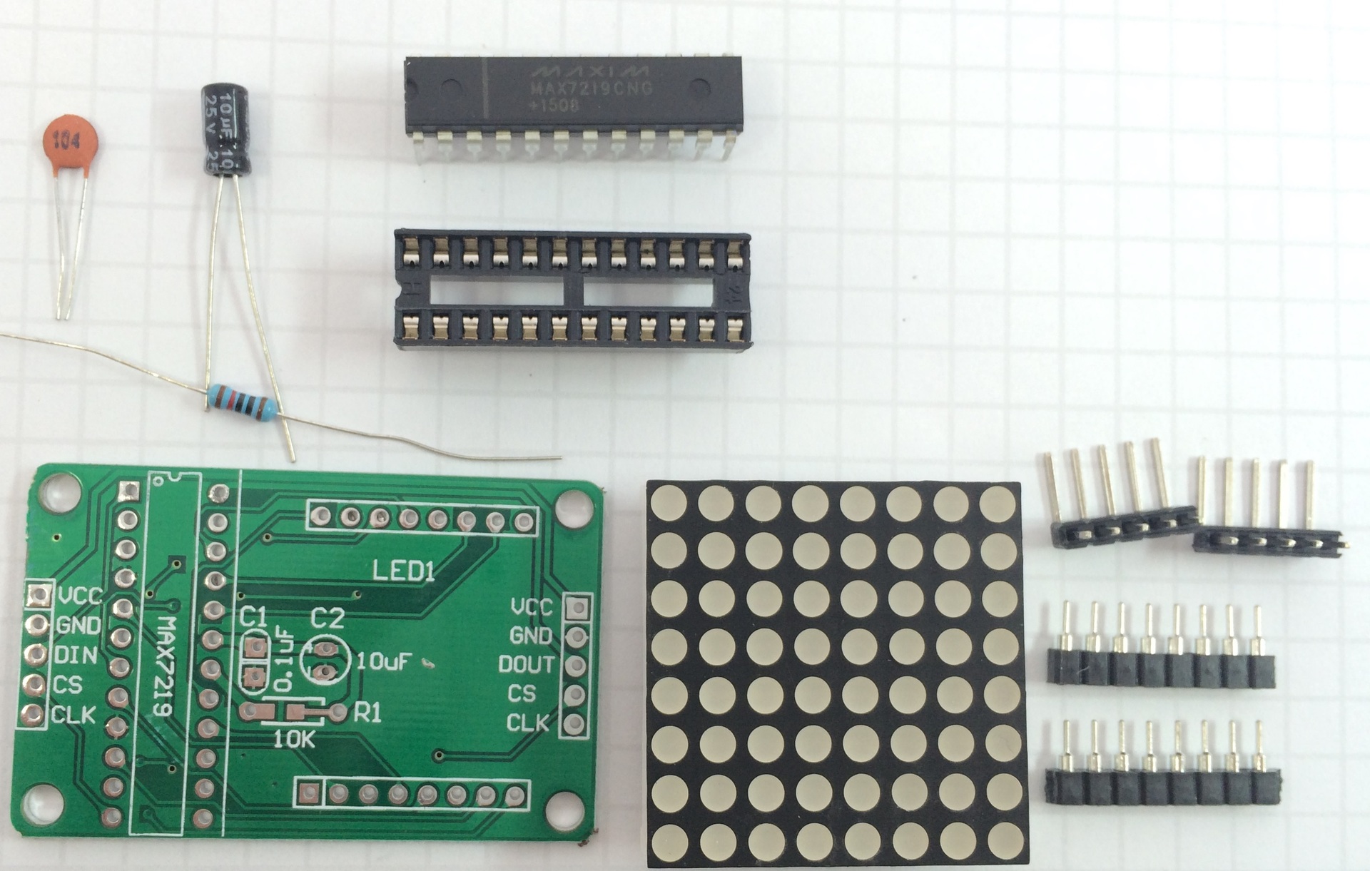
For a long time, an 8 * 8 LED array was in the box complete with a MAX7219 chip for its control, a 10 kΩ resistor, a 100 nF ceramic capacitor and a 10 μF electrolytic capacitor, a circuit board and several connectors. Kit is obtained as in the photo . Finally, I collected my strength and decided to connect it.
I was looking for a long time how to connect such a kit to raspberry and an example of a C + program, but I did not find it, but there are many examples for Arduino. It was possible to find only a sample code on python and configuration instructions , which, in the absence of the best, and used. And in this article I will tell in detail how to connect.
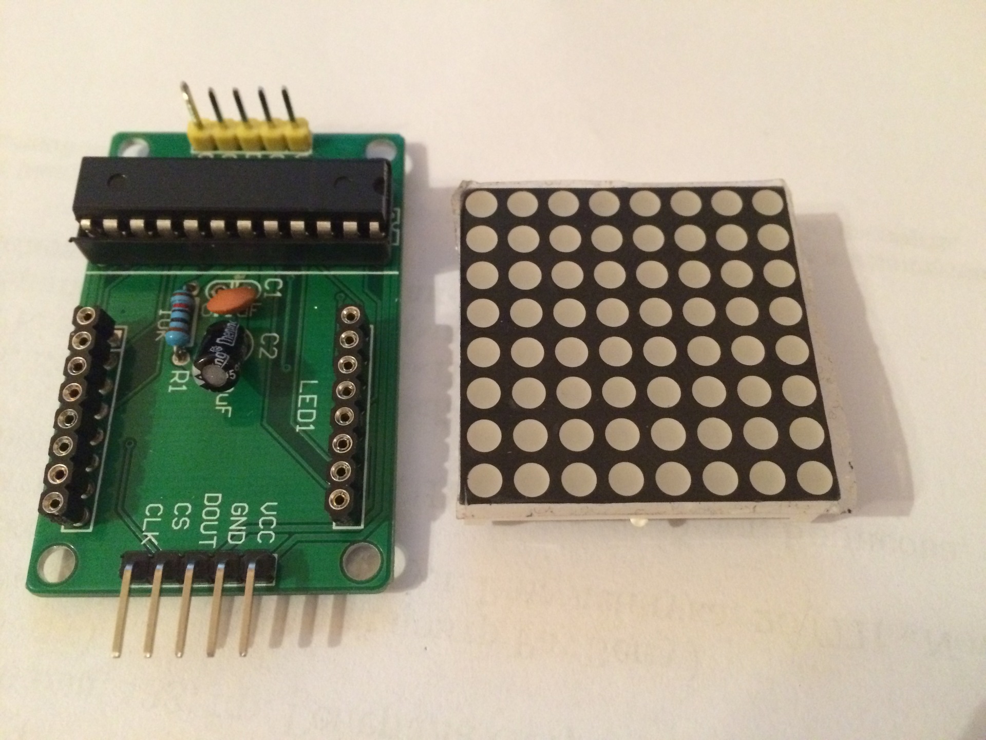
First, it is necessary to assemble this kit on a printed circuit board - everything is simple there, especially after reading the soldering instructions “soldering is simple . ”
')
Check if SPI is enabled. To do this, enter in the terminal:
It should get something like this:
If nothing is returned in response,
Check if we have SPI installed in / dev, for this we type in the terminal:
On the screen should get:
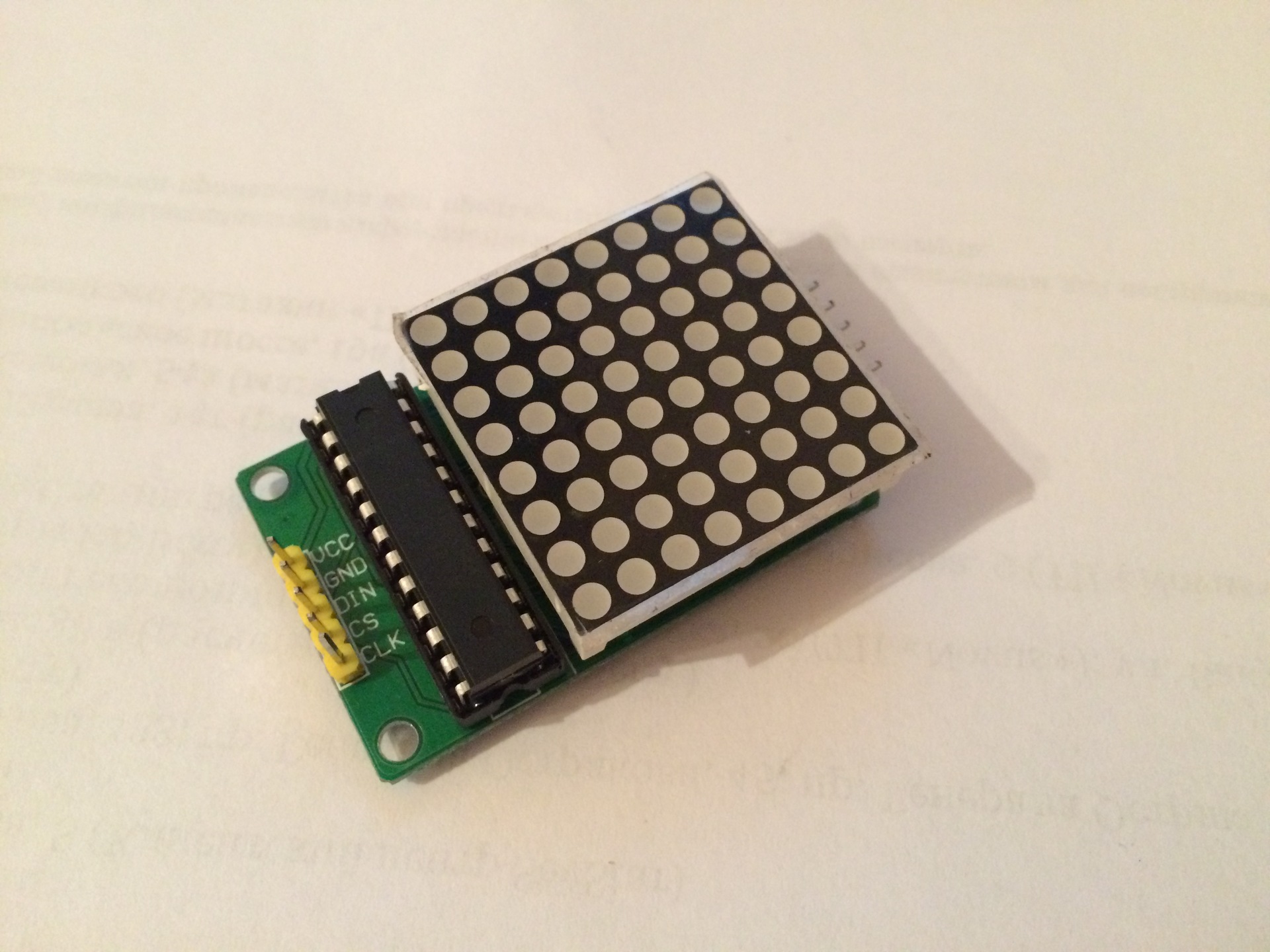
We connect our module to Raspberry:
VCC - to 5V raspberry
GND - to gnd
DIN (data in) - GPIO 10 (SPI MOSI)
CS (chip select) - GPIO 8 (SPI CS0)
CLK (clock) - GPIO 11 (SPI CLK)
On the other side of the module there are pins with similar designations - they are intended for the serial connection of modules.
Install the necessary programs to display information on the display
Download the library to work with the module:
Install the necessary components:
Run the existing example and check the operation of the module:
A running line with the text from the example should appear on the display. The text can be changed, for this we edit the file with the command:
The displayed text is shown in brackets after the device.show_message command.
An example of the display based on the idea dev_random :
I was looking for a long time how to connect such a kit to raspberry and an example of a C + program, but I did not find it, but there are many examples for Arduino. It was possible to find only a sample code on python and configuration instructions , which, in the absence of the best, and used. And in this article I will tell in detail how to connect.
First, it is necessary to assemble this kit on a printed circuit board - everything is simple there, especially after reading the soldering instructions “soldering is simple . ”
')
Getting Started Setting Raspberries
Check if SPI is enabled. To do this, enter in the terminal:
dmesg | grep spi It should get something like this:
[ 8.581285] spi spi0.0: setting up native-CS0 as GPIO 8 [ 8.589797] spi spi0.1: setting up native-CS1 as GPIO 7 If nothing is returned in response,
then we turn on SPI
Go to the program setting Raspberry:
Item 8 Advanced options> A6 SPI> Yes (would you like the SPI interface enabled?)> OK> Yes?
sudo raspi-config Item 8 Advanced options> A6 SPI> Yes (would you like the SPI interface enabled?)> OK> Yes?
Check if we have SPI installed in / dev, for this we type in the terminal:
ls -l /dev/spi* On the screen should get:
crw-rw---T 1 root spi 153, 0 Jan 1 1970 /dev/spidev0.0 crw-rw---T 1 root spi 153, 1 Jan 1 1970 /dev/spidev0.1 We connect our module to Raspberry:
VCC - to 5V raspberry
GND - to gnd
DIN (data in) - GPIO 10 (SPI MOSI)
CS (chip select) - GPIO 8 (SPI CS0)
CLK (clock) - GPIO 11 (SPI CLK)
On the other side of the module there are pins with similar designations - they are intended for the serial connection of modules.
Install the necessary programs to display information on the display
Download the library to work with the module:
git clone https://github.com/rm-hull/max7219.git Install the necessary components:
sudo apt-get install python-dev python-pip sudo pip install spidev sudo python setup.py install Run the existing example and check the operation of the module:
sudo python examples/matrix_test.py A running line with the text from the example should appear on the display. The text can be changed, for this we edit the file with the command:
nano examples/matrix_test.py The displayed text is shown in brackets after the device.show_message command.
An example of the display based on the idea dev_random :
Source: https://habr.com/ru/post/390419/
All Articles