Experiments based on the Digital Laboratory kit
In the first material , which tells about the training set “Digital Laboratory” NR05 , we outlined the construction principles, the composition of the set and the expansion card.
Let us now consider the training manual included in the set, and analyze two simple experiences using an expansion card that will help you understand how external devices are connected and how you can use the built-in buttons, we will give examples of sketches.
As we have said, the board contains groups of connectors for connecting various external modules: sensors, actuators, and devices that use some standard communication buses.
')
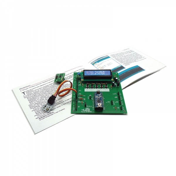
As an actuator, there is a place on the board for mounting a liquid-crystal two-line LCD character indicator with backlight. On such an indicator, it is possible to display enough information both for training purposes and when using the kit as a complete device. The tutorial tells how to display symbolic information on the display, how to make the display display Russian and English letters at the same time. The indicator is used in almost all the projects described in the brochure.
Consider the simplest actuator - LED. The set includes a tricolor (RGB - Red, Green, Blue) bright LED. Of the three colors of this LED by changing the intensity of each of them, due to the nature of the human eye, you can get any color. This method of obtaining color is called additive color mixing and is used, for example, in televisions and monitors. By mixing three colors in equal proportions, we get white.

We connect the LED to the XP15 connector of the expansion card, which is additionally labeled "RGB_LED" using four wires or an adapter. We use a LED with a common cathode (common “minus”), so the longest LED output is connected to the GND (“Ground”) contact, and the remaining LED leads are connected to the RED / D5 (red), BLUE / D6 (blue), GREEN contacts / D9 (green).
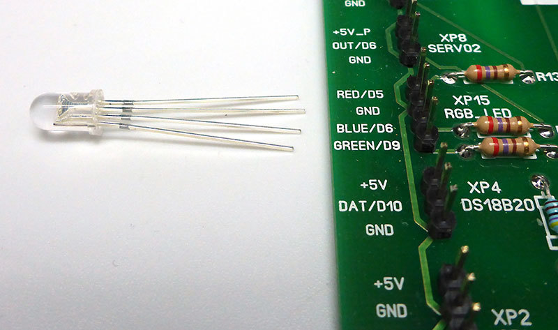
D5, D6 and D9 are Arduino’s digital outputs, where you can get pulse width modulation (PWM) to control the brightness of the LED. The tutorial presents the necessary minimum of the PWM theory and the method for implementing this modulation in Arduino.

Here is the program code (sketch) that controls the brightness of the RGB LED:
When you run the program, the LED gradually changes the emitted color from red to green, then from green to blue, and then from blue to red.
We will supplement our program in such a way that the LCD displays the values at each moment in time the corresponding brightness of each color from the minimum (0) to the maximum (255). The modified code is listed under the spoiler.
Now consider an example of the use of buttons built into the board.
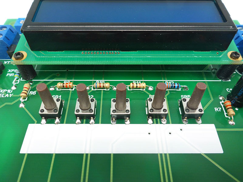
In the general case, each button is connected to a separate Arduino digital output, and the program sequentially polls these outputs in order to determine which button is pressed. To save the conclusions of the Arduino, which must be used to determine whether a button is pressed in the digital lab's expansion board, an “analog” keyboard is used, connected to just one analog input of the Arduino. This method is often used in household appliances. The program measures the output voltage at the output of the voltage divider, which depends on which button is pressed. The training manual discusses the theory of such a divider and how it is used in the keyboard. The disadvantage of this method is that the buttons can be pressed only one by one, sequentially.
Download the appropriate program in Arduino:
The LCD indicator is used to display information about which button is pressed. If you press the buttons, the number of the pressed button will be displayed on the indicator.
The get_key function returns an integer corresponding to the number of the pressed button, which can be used in the main program. Calibration values with which the voltage is compared from the output of the divider are determined experimentally using this program:
Try to load it into Arduino and see which values are displayed, and compare them with the calibration values. Let us now try to use the considered examples to create a program that implements LED control using buttons. Let's set the following functionality:
• pressing the button 1 (leftmost) lights up red light, the button 2– green, 3 - blue. When you press the button again, the corresponding light goes out. The display shows which colors are on.
• when you press button 4, the on and off colors change places
• when you press button 5, all colors go out.
Here is one of the possible options for this sketch:
In conclusion, we present a short video demonstrating the experiments described.
As you can see, the capabilities of the Digital Lab's expansion card allow you to conveniently, visually and quickly master the practice of working with Arduino and the connected additional modules.
In the next article we will look at the interaction of Arduino with Android-smartphone using Bluetooth technology using an expansion card. We will program the smartphone using the MIT App Inventor project, which is developed and supported by the Massachusetts Institute of Technology.
Let us now consider the training manual included in the set, and analyze two simple experiences using an expansion card that will help you understand how external devices are connected and how you can use the built-in buttons, we will give examples of sketches.
As we have said, the board contains groups of connectors for connecting various external modules: sensors, actuators, and devices that use some standard communication buses.
')
As an actuator, there is a place on the board for mounting a liquid-crystal two-line LCD character indicator with backlight. On such an indicator, it is possible to display enough information both for training purposes and when using the kit as a complete device. The tutorial tells how to display symbolic information on the display, how to make the display display Russian and English letters at the same time. The indicator is used in almost all the projects described in the brochure.
Consider the simplest actuator - LED. The set includes a tricolor (RGB - Red, Green, Blue) bright LED. Of the three colors of this LED by changing the intensity of each of them, due to the nature of the human eye, you can get any color. This method of obtaining color is called additive color mixing and is used, for example, in televisions and monitors. By mixing three colors in equal proportions, we get white.
We connect the LED to the XP15 connector of the expansion card, which is additionally labeled "RGB_LED" using four wires or an adapter. We use a LED with a common cathode (common “minus”), so the longest LED output is connected to the GND (“Ground”) contact, and the remaining LED leads are connected to the RED / D5 (red), BLUE / D6 (blue), GREEN contacts / D9 (green).
D5, D6 and D9 are Arduino’s digital outputs, where you can get pulse width modulation (PWM) to control the brightness of the LED. The tutorial presents the necessary minimum of the PWM theory and the method for implementing this modulation in Arduino.
Here is the program code (sketch) that controls the brightness of the RGB LED:
Spoiler
// RGB //----------------------------------------------------------------------- // int redPin = 5; int greenPin = 9; int bluePin = 6; //----------------------------------------------------------------------- /* 1 Arduino */ void setup() { } //----------------------------------------------------------------------- /* setup .*/ void loop() { /* 256 . value 1.*/ for(int value = 0 ; value <= 255; value ++) { // 0 analogWrite(redPin, 255-value); // analogWrite(greenPin, value); // analogWrite(bluePin, 0); // 30 delay(30); } /* 256 . value 1.*/ for(int value = 0 ; value <= 255; value ++) { // analogWrite(redPin, 0); // 0 analogWrite(greenPin, 255-value); // analogWrite(bluePin, value); // 30 delay(30); } /* 256 . value 1.*/ for(int value = 0 ; value <= 255; value ++) { // analogWrite(redPin, value); // analogWrite(greenPin, 0); // 0 analogWrite(bluePin, 255-value); // 30 delay(30); } // loop } When you run the program, the LED gradually changes the emitted color from red to green, then from green to blue, and then from blue to red.
We will supplement our program in such a way that the LCD displays the values at each moment in time the corresponding brightness of each color from the minimum (0) to the maximum (255). The modified code is listed under the spoiler.
Spoiler
// RGB //----------------------------------------------------------------------- // int redPin = 5; int greenPin = 9; int bluePin = 6; // int pwmRed; int pwmGreen; int pwmBlue; //----------------------------------------------------------------------- // LiquidCrystalRus #include <LiquidCrystalRus.h> // , LiquidCrystalRus #include <LiquidCrystalExt.h> #include <LineDriver.h> //----------------------------------------------------------------------- /* , RS,EN,DB4,DB5,DB6,DB7 */ LiquidCrystalRus lcd(A1, A2, A3, 2, 4, 7); // 1 Arduino void setup() { // LCD - 16 , 2 lcd.begin(16, 2); // () lcd.print(" RED GREEN BLUE"); } //----------------------------------------------------------------------- // setup . void loop() { /* 256 . value 1.*/ for(int value = 0 ; value <= 255; value ++) { pwmGreen = value; pwmRed = 255 - value; // 0 analogWrite(redPin, pwmRed); // analogWrite(greenPin, pwmGreen); // analogWrite(bluePin, 0); // 30 delay(30); Display(); } /* 256 . value 1.*/ for(int value = 0 ; value <= 255; value ++) { pwmBlue = value; pwmGreen = 255 - value; // analogWrite(redPin, 0); // 0 analogWrite(greenPin, pwmGreen); // analogWrite(bluePin, pwmBlue); // 30 delay(30); Display(); } /* 256 . value 1.*/ for(int value = 0 ; value <= 255; value ++) { pwmRed = value; pwmBlue = 255 - value; // analogWrite(redPin, pwmRed); // analogWrite(greenPin, 0); // 0 analogWrite(bluePin, pwmBlue); // 30 delay(30); Display(); } // loop } // , void Display(){ lcd.setCursor(0,1); lcd.print(" "); lcd.setCursor(1,1); lcd.print(pwmRed); lcd.setCursor(6,1); lcd.print(pwmGreen); lcd.setCursor(11,1); lcd.print(pwmBlue); } Now consider an example of the use of buttons built into the board.
In the general case, each button is connected to a separate Arduino digital output, and the program sequentially polls these outputs in order to determine which button is pressed. To save the conclusions of the Arduino, which must be used to determine whether a button is pressed in the digital lab's expansion board, an “analog” keyboard is used, connected to just one analog input of the Arduino. This method is often used in household appliances. The program measures the output voltage at the output of the voltage divider, which depends on which button is pressed. The training manual discusses the theory of such a divider and how it is used in the keyboard. The disadvantage of this method is that the buttons can be pressed only one by one, sequentially.
Download the appropriate program in Arduino:
Spoiler
// //----------------------------------------------------------------------- // LiquidCrystal #include <LiquidCrystal.h> // #define NUM_KEYS 5 // ( ) int adcKeyVal[NUM_KEYS] = {30, 150, 360, 535, 760}; //----------------------------------------------------------------------- // , RS,EN,DB4,DB5,DB6,DB7 LiquidCrystal lcd(A1, A2, A3, 2, 4, 7); //----------------------------------------------------------------------- // 1 Arduino void setup() { // LCD -16 2 lcd.begin(16, 2); // () // Keyboard lcd.print("Keyboard"); // 2000 = 2 delay(2000); } //----------------------------------------------------------------------- // setup . void loop() { // key int key; // , get_key key = get_key(); // lcd.clear(); // () // . - lcd.print(key); // 100 = 0,1 delay(100); // loop } //----------------------------------------------------------------------- // // , // , int get_key() { int input = analogRead(A6); int k; for(k = 0; k < NUM_KEYS; k++) if(input < adcKeyVal[k]) return k + 1; return 0; } The LCD indicator is used to display information about which button is pressed. If you press the buttons, the number of the pressed button will be displayed on the indicator.
The get_key function returns an integer corresponding to the number of the pressed button, which can be used in the main program. Calibration values with which the voltage is compared from the output of the divider are determined experimentally using this program:
#include <LiquidCrystal.h> LiquidCrystal lcd(A1, A2, A3, 2, 4, 7); void setup() { lcd.begin(16, 2); lcd.print("Press keys"); delay(2000); } void loop() { int input = analogRead(A6); lcd.clear(); lcd.print(input); delay(100); } Try to load it into Arduino and see which values are displayed, and compare them with the calibration values. Let us now try to use the considered examples to create a program that implements LED control using buttons. Let's set the following functionality:
• pressing the button 1 (leftmost) lights up red light, the button 2– green, 3 - blue. When you press the button again, the corresponding light goes out. The display shows which colors are on.
• when you press button 4, the on and off colors change places
• when you press button 5, all colors go out.
Here is one of the possible options for this sketch:
Spoiler
// RGB- //----------------------------------------------------------------------- // LiquidCrystal #include <LiquidCrystal.h> // #define NUM_KEYS 5 // ( ) int adcKeyVal[NUM_KEYS] = {30, 150, 360, 535, 760}; #define redLED 5 #define greenLED 9 #define blueLED 6 //----------------------------------------------------------------------- // , RS,EN,DB4,DB5,DB6,DB7 LiquidCrystal lcd(A1, A2, A3, 2, 4, 7); int redLEDstate = 0; int greenLEDstate = 0; int blueLEDstate = 0; int flag = 0; //----------------------------------------------------------------------- // 1 Arduino void setup() { pinMode(redLED, OUTPUT); pinMode(greenLED, OUTPUT); pinMode(blueLED, OUTPUT); // LCD -16 2 lcd.begin(16, 2); // () // lcd.print("Try Keys + LEDs"); // 1000 = 1 delay(1000); // lcd.clear(); } //----------------------------------------------------------------------- // setup . void loop() { // key int key; // , get_key key = get_key(); // , // C flag , if(key == 1 && flag == 0) { digitalWrite(redLED, !digitalRead(redLED)); flag = 1; } if(key == 2 && flag == 0) { // : if(key == 2 && !flag) digitalWrite(greenLED, !digitalRead(greenLED)); flag = 1; } if(key == 3 && !flag) { digitalWrite(blueLED, !digitalRead(blueLED)); flag = 1; } if(key == 4 && !flag) { digitalWrite(redLED, !digitalRead(redLED)); digitalWrite(greenLED, !digitalRead(greenLED)); digitalWrite(blueLED, !digitalRead(blueLED)); flag = 1; } if(key == 5 && !flag){ digitalWrite(redLED, LOW); digitalWrite(greenLED, LOW); digitalWrite(blueLED, LOW); flag = 1; } // , if(!key && flag) // if(key == 0 && flag == 1) { flag = 0; } // , if (digitalRead(redLED)) { // if (digitalRead(redLED) == 1) lcd.setCursor(0,0); lcd.print("Red"); } else { lcd.setCursor(0,0); lcd.print(" "); } if (digitalRead(greenLED)) { lcd.setCursor(5,0); lcd.print("Green"); } else { lcd.setCursor(5,0); lcd.print(" "); } if (digitalRead(blueLED)) { lcd.setCursor(11,0); lcd.print("Blue"); } else { lcd.setCursor(11,0); lcd.print(" "); } // loop } //----------------------------------------------------------------------- // // , // , int get_key() { int input = analogRead(A6); int k; for(k = 0; k < NUM_KEYS; k++) if(input < adcKeyVal[k]) return k + 1; return 0; } In conclusion, we present a short video demonstrating the experiments described.
As you can see, the capabilities of the Digital Lab's expansion card allow you to conveniently, visually and quickly master the practice of working with Arduino and the connected additional modules.
In the next article we will look at the interaction of Arduino with Android-smartphone using Bluetooth technology using an expansion card. We will program the smartphone using the MIT App Inventor project, which is developed and supported by the Massachusetts Institute of Technology.
Source: https://habr.com/ru/post/390345/
All Articles