Development of a low-power backup power source with a sine output. Part 1. Problem statement
Uninterruptible power supplies (UPS) are widely used both in everyday life and in industry. They are designed to provide the necessary power supply equipment from backup sources in case of "loss" of the main power supply. Backup sources in such UPSs are mainly batteries. Therefore, these UPSs provide power to the equipment for a limited time, from a few minutes to a couple of three hours. On sale there is a huge amount of such equipment, as they say, for every taste and color "pocket", with various characteristics and various functions.
Consider the scope of application in everyday life.
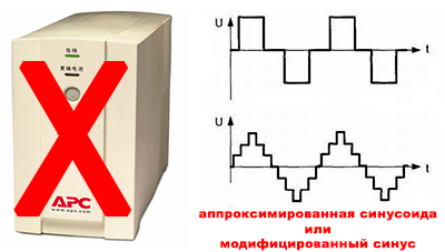
Each house has a fridge. The main models use a compressor driven by a bipolar single-phase asynchronous electric motor. The power of household refrigerators 100-200 watts. The loss of the main power supply (a la 220 volts) for a few hours can lead to the defrosting of the refrigerator. This is not critical, but inconvenient. But the usual computer UPS does not help here: the compressor engine will not be pleased with the form of voltage provided by such a UPS. For this kind of consumer, a sine is required at the output of the UPS.
')
An example, let's say honestly, the most real, but not the most necessary for the use of UPS.
Private house, heating system, circulation pump. Same problems. Modern gas boilers basically have it in their design. With the loss of power from a computer UPS, they also do not particularly want to work. True, you can survive for a couple of hours without electricity and a working boiler, since for a couple of hours it will not cool to negative temperatures.
Continue to look for the use of UPS with a sine output in the home.
The same private house, a circulation pump in the heating system, but the heating system itself is not on gas, but on wood. That means you have melted the stove after work and warm the house, the pump pumps fluid through the pipelines of the heating system. Bam! Turned off the electricity. The boiler began to overheat wildly, due to the lack of circulation, but this is not the gas valve to shut off, the stove will have to be extinguished, in the direct and figurative sense. And if there were a UPS, then quietly, in an hour and a half, you could heat the stove and continue to wait until the electric grid restores the supply ofnatural gas with electricity. Already more real. Further.
The village has natural gas, there is a floor boiler of AOGV-11.6-3 type. Here is its description: it is intended for electron-independent autonomous systems of heating houses, cottages of up to 110 sq. M. So for his work electricity is not needed. But for the circulation of the coolant is used a circulation pump. The lack of electricity at work of the boiler does not affect in any way, but due to the lack of circulation, the water in the boiler starts to boil and it is squeezed out through the expansion tank with all the ensuing consequences. So in this situation, you have to turn off the boiler. But if the owners are not at home, or does it happen at night?
Here for such a specific case and needed UPS with a sine. Developing a full-fledged UPS for this task does not make sense. If the transition time from the network to the backup source will be 5-10 seconds, nothing critical will happen, both with the heating system and with the pump itself.
From the above, and the task follows: to develop a low-power backup power source of 220 V, 50 Hz with a sine output.
Let us turn to the market and examine the available offers. To do this, we set some criteria for the equipment to be selected. Requests will be modest.
Google didn’t enjoy the results of the query “UPS 200 W with sine”. Almost the very first link tells about the calculation and selection of the UPS to the gas heating boiler. Truth, the price of the UPS does not please the eye, especially if you look at the batteries, which are not included in the UPS package - it becomes sad at all. For the rest of the links the same story that does not please the usualmortal representative of the middle class.
There are many different UPSs on the market, why develop something? There are several answers to this question:
For the time being, we keep silent about the price of the developed device, as long as there are no specific “figures”. But after testing the device, we calculate all the costs of consumables.
Let's start with the necessary calculations. Let us estimate the power that the RIP needs to give to the load, battery life, etc. Let's get started
The load we will have a circulation pump. Let's look at common models on the market. This is what Google has issued: a link to the characteristics of circulation pumps.
For houses of a small area up to 100 sq. M, pumps up to 100 W are used. And rarely uses the third power mode pumps. So let's stop at 60 watts of power consumption. Here we will make a start from this power at calculations.
The voltage at the output RIP 230 V. Power 60 watts. Therefore, the current will be I = P / U = 60/230 = 260 mA.
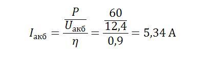
Now let us ask the efficiency of the converter 12 V DC -> 230 V AU in the region of 90%, then at a supply voltage from the battery of 12.4 Volts the current consumption from the battery will be:
We will rely on these figures, both when choosing electronic components and in the manufacture of printed circuit boards.
For the converter 12-> 220, a step-up SMPS circuit is applied. That is, using a pulsed step-up transformer, 310 Volts of direct voltage are obtained, and then using a bridge circuit controlled by a sinusoidal shim and an LC filter, a “pure” 220-volt sine is obtained at the output. This approach uses many components from integrated circuits to high-speed diodes, etc. After all, pulse circuitry.
For a given RIP with itsnegligible low power, you can go a little different way.
From the so-called DC link, which in our case will be the battery bus, that is, 12 volts, through a bridge circuit controlled by a sinusoidal shim, apply to the primary winding of a conventional linear network step-up transformer. With the secondary remove the necessary 220 volts of sinusoidal voltage. The benefit for such power and dimensions of the transformer will not be large. The transformer itself will serve as a filter and smooth the voltage form almost to a recognizable sine. And if a low-impedance LC filter is placed between the bridge and the primary winding of the transformer, you can get a form of voltage at the output of the transformer very close to the sine.
It turns out about this scheme.
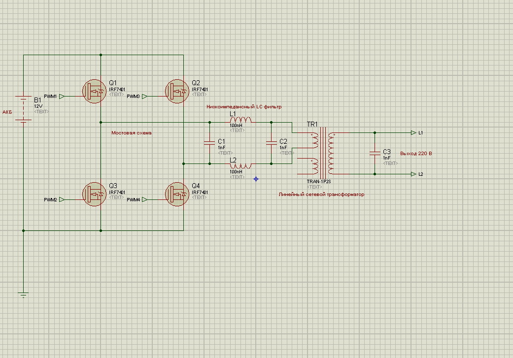
The picture is clickable
In this sample diagram, the components are taken to show the basic thought of the RIPA circuit design, and their face values do not correspond to the calculations that we will make below. The circuit itself becomes more complex as the device is designed.
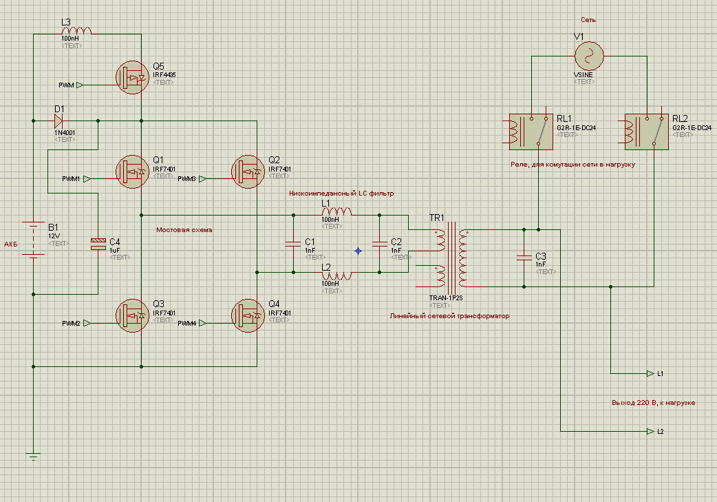
At the time when the pump is operating from the RIP, the battery is discharged, and after switching from the RIP to the network, it makes sense to charge the battery to the nominal capacity. When “electricity is present in the outlet”, the pump operates from the mains, and the RIP output circuit can be used to charge the battery. That is, supply the mains voltage to the secondary winding of the transformer (it is high voltage), remove the alternating voltage from the primary winding (it is low voltage), straighten it on the diode bridge, smooth it with a capacitor and charge the battery with it. Consider the changes that need to be made to the scheme for this approach.
The picture is clickable
That is, as long as there is voltage in the network, the relays are tightened, and the mains voltage through the relay contacts enters the load, as well as the high-voltage winding of the transformer. Next, the voltage is removed from the low-voltage winding. The voltage is rectified by parasitic diodes of transistors (for correctness, we should point out that we will not use them in a real circuit, we will install external high-speed diodes parallel to the transistors to the required current), smoothed by a capacitor and through the P-channel transistor controlled by the control circuit to the MK, downloads the required charging current in the battery through a smoothing choke.
When the electricity "ends" in the network, the relay opens, and the circuit will work in reverse order. From 12 volt battery through the bridge transistors, filters and transformer voltage will be applied to the load.
In order not to sculpt synchronization with the network, etc. for an almost instantaneous transition from the battery to the network and back, it’s trite if the network is lost, the load will be de-energized, the relay will open, the circuit will prepare everything and everyone for operation from the battery and will generate a voltage to the load. When the network is restored, the circuit will stop the generation of voltage, make sure that everything is fine, and close the relay for switching to the network and charging the battery. The functions of the control scheme will be outlined during the development process.
The structural scheme and the basic principle of operation of the RIP have been dismantled and, with this positive mood, we proceed to the calculations of the necessary components of the scheme and the choice of a hardware platform, both for the “brains” of the device and for the power elements. The truth is in the next article.
In the following parts we will look at the calculations of the developed RIP, prepare the circuit diagram of the device, choose the hardware platform, and develop the topology of the printed circuit board for the RIP. We will analyze the functions of the device, write programs for the MC, carry out a full cycle of setting up and testing the device on the equipment, and also hand over all this to the real customer.
PS: True, the development will take some time, and further publications will be published as the project progresses. Focusing on three more articles, with an interval of about 2-3 weeks.
Continued here:
Part number 2.
Part number 3.
Consider the scope of application in everyday life.
Each house has a fridge. The main models use a compressor driven by a bipolar single-phase asynchronous electric motor. The power of household refrigerators 100-200 watts. The loss of the main power supply (a la 220 volts) for a few hours can lead to the defrosting of the refrigerator. This is not critical, but inconvenient. But the usual computer UPS does not help here: the compressor engine will not be pleased with the form of voltage provided by such a UPS. For this kind of consumer, a sine is required at the output of the UPS.
')
An example, let's say honestly, the most real, but not the most necessary for the use of UPS.
Private house, heating system, circulation pump. Same problems. Modern gas boilers basically have it in their design. With the loss of power from a computer UPS, they also do not particularly want to work. True, you can survive for a couple of hours without electricity and a working boiler, since for a couple of hours it will not cool to negative temperatures.
Continue to look for the use of UPS with a sine output in the home.
The same private house, a circulation pump in the heating system, but the heating system itself is not on gas, but on wood. That means you have melted the stove after work and warm the house, the pump pumps fluid through the pipelines of the heating system. Bam! Turned off the electricity. The boiler began to overheat wildly, due to the lack of circulation, but this is not the gas valve to shut off, the stove will have to be extinguished, in the direct and figurative sense. And if there were a UPS, then quietly, in an hour and a half, you could heat the stove and continue to wait until the electric grid restores the supply of
The village has natural gas, there is a floor boiler of AOGV-11.6-3 type. Here is its description: it is intended for electron-independent autonomous systems of heating houses, cottages of up to 110 sq. M. So for his work electricity is not needed. But for the circulation of the coolant is used a circulation pump. The lack of electricity at work of the boiler does not affect in any way, but due to the lack of circulation, the water in the boiler starts to boil and it is squeezed out through the expansion tank with all the ensuing consequences. So in this situation, you have to turn off the boiler. But if the owners are not at home, or does it happen at night?
Here for such a specific case and needed UPS with a sine. Developing a full-fledged UPS for this task does not make sense. If the transition time from the network to the backup source will be 5-10 seconds, nothing critical will happen, both with the heating system and with the pump itself.
From the above, and the task follows: to develop a low-power backup power source of 220 V, 50 Hz with a sine output.
Foreword
Let us turn to the market and examine the available offers. To do this, we set some criteria for the equipment to be selected. Requests will be modest.
- Power - 200 W,
- "Pure" sine output
- Well ... enough.
Google didn’t enjoy the results of the query “UPS 200 W with sine”. Almost the very first link tells about the calculation and selection of the UPS to the gas heating boiler. Truth, the price of the UPS does not please the eye, especially if you look at the batteries, which are not included in the UPS package - it becomes sad at all. For the rest of the links the same story that does not please the usual
Introduction
There are many different UPSs on the market, why develop something? There are several answers to this question:
- The price of the proposed devices, though not transcendental, but still high,
- The function of the "pure" sinus is more expensive and is far from widespread,
- Understand the princes of building such systems
- To gain experience in the design, development of power electronics,
- Experience in programming MK
- Everyone can continue the list for self-motivation ...
For the time being, we keep silent about the price of the developed device, as long as there are no specific “figures”. But after testing the device, we calculate all the costs of consumables.
Lyrical digression
On geektimes.ru there is a series of articles devoted to the design of a powerful UPS with a pure sine output. Starting post is on this link . In this cycle, we will not develop a full reduced copy of this UPS, but we will approach the specific task a little differently. And the developed device to call the UPS language will not turn. This will be a backup power source with automatic transfer of reserve (hereinafter referred to as RIP ATS), in which the transition time from the network to the RIP will be on the order of a couple of seconds.
Initial data
Let's start with the necessary calculations. Let us estimate the power that the RIP needs to give to the load, battery life, etc. Let's get started
The load we will have a circulation pump. Let's look at common models on the market. This is what Google has issued: a link to the characteristics of circulation pumps.
For houses of a small area up to 100 sq. M, pumps up to 100 W are used. And rarely uses the third power mode pumps. So let's stop at 60 watts of power consumption. Here we will make a start from this power at calculations.
Lyrical digression
If someone needs more power, then for this it is necessary to proportionally increase the values obtained in the calculations, and from the data obtained recount the electronic components used in the circuit (diodes, transistors, etc.).
The voltage at the output RIP 230 V. Power 60 watts. Therefore, the current will be I = P / U = 60/230 = 260 mA.
Now let us ask the efficiency of the converter 12 V DC -> 230 V AU in the region of 90%, then at a supply voltage from the battery of 12.4 Volts the current consumption from the battery will be:
We will rely on these figures, both when choosing electronic components and in the manufacture of printed circuit boards.
RIP Structural Diagram
For the converter 12-> 220, a step-up SMPS circuit is applied. That is, using a pulsed step-up transformer, 310 Volts of direct voltage are obtained, and then using a bridge circuit controlled by a sinusoidal shim and an LC filter, a “pure” 220-volt sine is obtained at the output. This approach uses many components from integrated circuits to high-speed diodes, etc. After all, pulse circuitry.
For a given RIP with its
From the so-called DC link, which in our case will be the battery bus, that is, 12 volts, through a bridge circuit controlled by a sinusoidal shim, apply to the primary winding of a conventional linear network step-up transformer. With the secondary remove the necessary 220 volts of sinusoidal voltage. The benefit for such power and dimensions of the transformer will not be large. The transformer itself will serve as a filter and smooth the voltage form almost to a recognizable sine. And if a low-impedance LC filter is placed between the bridge and the primary winding of the transformer, you can get a form of voltage at the output of the transformer very close to the sine.
It turns out about this scheme.
The picture is clickable
In this sample diagram, the components are taken to show the basic thought of the RIPA circuit design, and their face values do not correspond to the calculations that we will make below. The circuit itself becomes more complex as the device is designed.
At the time when the pump is operating from the RIP, the battery is discharged, and after switching from the RIP to the network, it makes sense to charge the battery to the nominal capacity. When “electricity is present in the outlet”, the pump operates from the mains, and the RIP output circuit can be used to charge the battery. That is, supply the mains voltage to the secondary winding of the transformer (it is high voltage), remove the alternating voltage from the primary winding (it is low voltage), straighten it on the diode bridge, smooth it with a capacitor and charge the battery with it. Consider the changes that need to be made to the scheme for this approach.
The picture is clickable
That is, as long as there is voltage in the network, the relays are tightened, and the mains voltage through the relay contacts enters the load, as well as the high-voltage winding of the transformer. Next, the voltage is removed from the low-voltage winding. The voltage is rectified by parasitic diodes of transistors (for correctness, we should point out that we will not use them in a real circuit, we will install external high-speed diodes parallel to the transistors to the required current), smoothed by a capacitor and through the P-channel transistor controlled by the control circuit to the MK, downloads the required charging current in the battery through a smoothing choke.
When the electricity "ends" in the network, the relay opens, and the circuit will work in reverse order. From 12 volt battery through the bridge transistors, filters and transformer voltage will be applied to the load.
In order not to sculpt synchronization with the network, etc. for an almost instantaneous transition from the battery to the network and back, it’s trite if the network is lost, the load will be de-energized, the relay will open, the circuit will prepare everything and everyone for operation from the battery and will generate a voltage to the load. When the network is restored, the circuit will stop the generation of voltage, make sure that everything is fine, and close the relay for switching to the network and charging the battery. The functions of the control scheme will be outlined during the development process.
The structural scheme and the basic principle of operation of the RIP have been dismantled and, with this positive mood, we proceed to the calculations of the necessary components of the scheme and the choice of a hardware platform, both for the “brains” of the device and for the power elements. The truth is in the next article.
And again lyrical digression
Recently, I published a series of articles on Habré titled "Measuring the weight of minerals in the mining industry." But apparently I miscalculated with the target audience of Habr, so I post the development of RIP here on Geektimes . If anyone is interested in reading my previous publications, I will leave here links to this material:
- Measuring the weight of minerals in the mining industry. Theoretical basis
- Measurement of ore weight by stator current. Practice. Part 1. Signal processing algorithm in MK
- Measurement of ore weight by stator current. Practice. Part 2. Software implementation at MK
Conclusion
In the following parts we will look at the calculations of the developed RIP, prepare the circuit diagram of the device, choose the hardware platform, and develop the topology of the printed circuit board for the RIP. We will analyze the functions of the device, write programs for the MC, carry out a full cycle of setting up and testing the device on the equipment, and also hand over all this to the real customer.
PS: True, the development will take some time, and further publications will be published as the project progresses. Focusing on three more articles, with an interval of about 2-3 weeks.
Continued here:
Part number 2.
Part number 3.
Source: https://habr.com/ru/post/390151/
All Articles