Outlet 2.0: Our Answer Tesla
Smart House. The concept of a truly modern home, where with the help of technology a person is provided with complete comfort. More and more people are buying ready-made solutions. unfortunately (especially because of the current exchange rate), many of these kits have greatly increased in price and often have become too costly a way to “touch the future.” And it remains to be glad that, as before, inquiring minds are developing more and more new DIY-ways to automate their homes.
I would like to tell you about the project that I spied on the BQ website. It always seemed to me that the “Smart Home” is a complex technology, and a person without a deep understanding of engineering and electronics should not even go there. But as it turned out, everything is somewhat simpler.
')
This project describes how to use the arduino-compatible board, a simple extension cable with a button, a protocoder, and a smartphone to turn the light on and off using voice commands. The basic principle is that you connect remotely to the board using bluetooth and by running the application on your smartphone, you can give a specific command. But first things first.
Installation
The first thing you need to do is, of course, integrate the board into your extension cable.

For this, first of all, this very extension cable must be dismantled in an absolutely barbaric way. Caring Spaniards with a large caps warn that before these manipulations the extension itself would be nice to disconnect from the power supply.
After you disassemble the extension cable, you can safely postpone the button - you will no longer need it. You are interested in the wires that entered it - there are only two of them. Most often they are blue and brown in color - and we will build on them. Blue wire should be immediately soldered and set shrink - these are plastic “tubes” that you can easily find in any store for radio amateurs. This must be done, otherwise the exposed part of the wires may soon lead to consequences that are not foreseen by the project.
The second wire is not necessary to solder. There you will have two ends of a brown wire. They need to be installed in an arduino-compatible relay. The end coming from the power cord is installed at the terminal C - central. With it you will not lose, it is in the middle. And the wire from the “sockets” - to the NO (normally open) terminal. If your relay has no marking, turn it upside down. Left - the one that you require.
If everything is done correctly, then now your extension from the inside will look something like this:

After that, the extension cord can be “closed” by first passing the relay wire to connect the board through the hole left of the button. The manipulations with the insides are finished.

Now you need to install the board itself. The example uses bq ZUM, the principal difference of which, in this case, lies in the integrated bluetooth module. However, ZUM can be replaced by another motherboard, for example, Freeduino Uno. But then you will additionally need the missing module.
In order to secure the electronics on the extension cord, you will also need parts that are printed on a 3D printer. In addition to a small platform for the board, the number of parts also includes a container for the nutrient module, where the batteries are installed. Surely with the help of additional electronics you can power the board from the extension cord, but this example, unfortunately, is not considered.

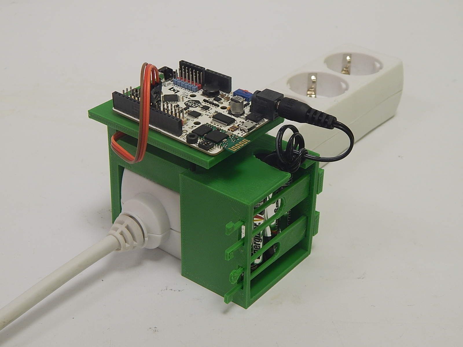
Having finally collected all the electronics, we install it. The end result looks pretty nice, but the software part still remains.
Protocoder.
Protooder is a programming environment + JavaScript framework for quickly building prototypes that can be used on Android devices. It is very easy to install.

The sketch for this project is laid out by the Spaniards in open access and there is nothing to program. On the mobile screen, the application looks like this:

Do not be intimidated by foreign non-English words, in the source code you can change the labels to those that you want. In the application, we see three buttons. And this is what each of them means:
Conectar bluetooth - as it is not difficult to guess, by pressing this button you can, through Protocoder, join the desired device via bluetooth. In our case, this device is a board;
Desconectar is, accordingly, a disconnection. A very useful feature, given that while the connection is established, you will not be able to make changes to the code of the programmable board;
Hablar - “speak”. Clicking this button will open the familiar google voice input service. It is by pressing this button that you will “enter” your commands;

Here is the code for Protocoder and your smartphone:
var bluetoothOn=0; ui.addButton("Conectar bluetooth", 10, 150, function() { network.connectBluetoothSerialByUi(function(m, data) { txt.text(data + "\n"); }); bluetoothOn=1; }) ui.addButton("Desconectar", 380, 150, function() { network.disconnectBluetooth(); }) ui.addButton("Hablar", 280, 550, function() { media.startVoiceRecognition(function(text) { console.log(text); if (bluetoothOn==1) { if(text=="enciende") network.sendBluetoothSerial("=on+"); if(text=="apaga") network.sendBluetoothSerial("=off+"); if(text=="parpadea cada segundo") network.sendBluetoothSerial("=1+"); if(text.substring(0,13)=="parpadea cada" && text.substring(14,21)!="segundo" ) network.sendBluetoothSerial("="+text.split(" ")[2]+"+"); } }); }) Carefully look at him. You will find on the 19th, 20th and 21st lines such words - enciende (“Turn on”), apaga (“Turn off”) and parpadea cada segundo (“Blink every second”). If you do not want to train your Spanish, these words should be replaced by more familiar ones. It is not difficult to guess what each of the teams is doing.
Now your mobile can join the board and give it commands. But she herself is not able to perceive them yet - she also needs to be programmed.
First of all, if you are going to use the sources of the Spaniards, make sure that the relay is connected to the board in the correct pins:

Are you convinced? Then it's time to fill in the code. This is done using the Arduino IDE. Here is the code:
String inString =""; int pinRele=7; void setup() { Serial.begin(19200); Serial.flush(); pinMode(pinRele, OUTPUT); pinMode(13, OUTPUT); } void readFromAndroid(){ char inChar; while(Serial.available()>0){ inChar =(char) Serial.read(); Serial.flush(); if (inChar=='='){ inString=""; } else if(inChar!='+'){ inString+=inChar; } } } void writeData(){ if (inString=="on") { digitalWrite(13, HIGH); digitalWrite(pinRele, HIGH);} else if (inString=="off") { digitalWrite(13, LOW); digitalWrite(pinRele, LOW);} else if (inString.toInt()){ digitalWrite(13, HIGH); digitalWrite(pinRele, HIGH); delay(inString.toInt() *1000 ); digitalWrite(13, LOW); digitalWrite(pinRele, LOW); delay(inString.toInt() *1000 ); } } void loop() { if (Serial.available()>0){ readFromAndroid(); } writeData(); } An important point. If you do not use the bq ZUM board, then there is a high probability that the Bluetooth module is installed at a different speed. Then you need to replace the line:
Serial.begin(19200); On, for example:
Serial.begin(9600); There are also enough examples on the Internet how to change the data transfer rate of the bluetooth module itself.
So, after installing the program on both the smartphone and the board, our project is completed. It's time to take fresh batteries, connect the extension cord to the network, and to it, for example, a lamp. What do you have to get out in the end? Demonstration - in the video:
Of course, activation on / off with voice commands is not a smart home. But the main thing is the idea. And the idea is that with the help of DIY-projects, anyone can easily be Jack, who will build a house. Very smart home.
PS Link to project files
PSS I hope Elis Musk for Tesla for 400 tysjach dollarov. Spasibo!
Source: https://habr.com/ru/post/390045/
All Articles