AMS and magic crystal

This time I propose to do some magic (why not?) And create a magic crystal for our everyday needs. We will use it for its intended purpose - to prophesy various non-obvious entities and events. And we need only two ingredients to make this artifact - the Arduino Mega Server and the nooLite SD111-180 wireless LED tape controller .
A crystal will not be decorative (to deceive a gullible public), but a functional one, with many magical properties.
')
So let's get started ...
School of Magic
As you understand, you cannot just take and perform some kind of miracle, you must first go through the school of magic and master the basics of this complex art. And here I refer you to a series of articles ( one , two , three ) about the integration of nooLite equipment into home automation systems and recommend reading them before further reading. These articles detail all the basics and technical details of how the Arduino Mega Server works with nooLite wireless equipment. Therefore, all further narrative I will lead assuming that you have already read the previous articles.
Module
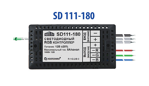
We will carry out all the experiments with the nooLite SD111-180 wireless controller, which allows you to control the LED strips "over the air" without any wires. The connection, as always with nooLite, is the simplest - two wires to the power supply for LED strips and four to the tape itself: the plus and three channels R, G, B.
Software part
The previous articles talked about the nooLite control kernel integrated into the Arduino Mega Server system. And there it was also mentioned that the core implements a basic set of functions for controlling nooLite devices and was suggested for everyone, by analogy, to add other necessary functions to the core. Now we will facilitate this task and add functions to the core for wireless control of LED strips.
First of all, we add the “main” function, which generates control commands for the nooLite MT1132 module.
void nooSendCommandLed(byte channel, byte command, byte r, byte g, byte b, byte format) { byte buf[12]; ledLastState[0] = r; ledLastState[1] = g; ledLastState[2] = b; for (byte i = 0; i < 12; i++) { buf[i] = 0; } buf[0] = 85; buf[1] = B01010000; buf[2] = command; buf[3] = format; buf[5] = channel; buf[6] = r; buf[7] = g; buf[8] = b; int checkSum = 0; for (byte i = 0; i < 10; i++) { checkSum += buf[i]; } buf[10] = lowByte(checkSum); buf[11] = 170; for (byte i = 0; i < (12); i++) { Serial1.write(buf[i]); } } This is the sister of the nooSendCommand function, which we discussed in the first article. It is only slightly modified for the specific management needs of LED strips. Added installation of 6, 7, 8 bytes of the control command, which contain the brightness of the three channels R, G, B. And the array is added
byte ledLastState[] = {127, 127, 127}; containing the last set color value of the LED strip. This is necessary in order to be able to turn on and off the light while maintaining the set color value. If this is not done, then after turning it off and then on, the color will be reset to white, which is not very convenient.
And to work with the LED strip, select the third channel
byte const NOO_CHANNEL_3 = 2; One could choose any of the other 32 channels with which the nooLite MT1132 module works.
Now we have a basic function that controls the operation of the nooLite SD111-180 LED tape controller, and, accordingly, the LED strip itself. And now we can start writing wrapper functions that will make it easier for us to write code to control the color of the glow of the tape.
Base wrapper
void nooLed (byte ch, byte r, byte g, byte b) { nooSendCommandLed(ch, 6, r, g, b, 3); } Just specify the channel and the color of the glow. We have 16 million colors. Further we write wrapper functions for basic colors (you can add such functions for your favorite colors).
void nooRed (byte ch, byte v) {nooSendCommandLed(ch, 6, v, 0, 0, 3);} void nooGreen (byte ch, byte v) {nooSendCommandLed(ch, 6, 0, v, 0, 3);} void nooBlue (byte ch, byte v) {nooSendCommandLed(ch, 6, 0, 0, v, 3);} void nooYellow (byte ch, byte v) {nooSendCommandLed(ch, 6, v, v, 0, 3);} void nooMagenta(byte ch, byte v) {nooSendCommandLed(ch, 6, v, 0, v, 3);} void nooCyan (byte ch, byte v) {nooSendCommandLed(ch, 6, 0, v, v, 3);} Simply indicate the channel and the intensity of the glow in the range from 0 to 255. And a few more "conceptual" functions. White, black and gray intensity.
void nooBlack (byte ch) {nooSendCommandLed(ch, 6, 0, 0, 0, 3);} void nooWhite (byte ch) {nooSendCommandLed(ch, 6, 255, 255, 255, 3);} void nooGray (byte ch, byte v) {nooSendCommandLed(ch, 6, v, v, v, 3);} And the last function, which we will add to the nooLite core in the Arduino Mega Server system, is the function of restoring the last color of the glow of the tape (the nooLite modules themselves do not remember this value). This feature is used to turn on the tape (after shutdown, which resets the color to white).
void nooSetLedLastState(byte ch) { nooSendCommandLed(ch, 6, ledLastState[0], ledLastState[1], ledLastState[2], 3); } Here is the complete code for the new nooLite control kernel.
Full kernel code
/* Modul nooLite for Due part of Arduino Mega Server project */ #ifdef NOO_FEATURE byte const PIN_TX = 18; // TX PIN (to RX noolite) byte const PIN_RX = 19; // RX PIN (to TX noolite) byte const NOO_CHANNEL_1 = 0; // channel (address) 0...31 (MT1132) byte const NOO_CHANNEL_2 = 1; byte const NOO_CHANNEL_3 = 2; byte const NOO_CHANNEL_4 = 3; byte const NOO_CHANNEL_5 = 4; void nooInit() { Serial1.begin(9600); modulNoo = MODUL_ENABLE; started("nooLite"); } void nooWork() { } void nooSendCommand(byte channel, byte command, byte data, byte format) { byte buf[12]; for (byte i = 0; i < 12; i++) { buf[i] = 0; } buf[0] = 85; buf[1] = B01010000; buf[2] = command; buf[3] = format; buf[5] = channel; buf[6] = data; int checkSum = 0; for (byte i = 0; i < 10; i++) { checkSum += buf[i]; } buf[10] = lowByte(checkSum); buf[11] = 170; for (byte i = 0; i < (12); i++) { Serial1.write(buf[i]); } /* Serial.println(">"); for (byte i = 0; i < (12); i++) { Serial.print(buf[i]); } Serial.println(); */ } byte ledLastState[] = {127, 127, 127}; void nooSendCommandLed(byte channel, byte command, byte r, byte g, byte b, byte format) { byte buf[12]; ledLastState[0] = r; ledLastState[1] = g; ledLastState[2] = b; for (byte i = 0; i < 12; i++) { buf[i] = 0; } buf[0] = 85; buf[1] = B01010000; buf[2] = command; buf[3] = format; buf[5] = channel; buf[6] = r; buf[7] = g; buf[8] = b; int checkSum = 0; for (byte i = 0; i < 10; i++) { checkSum += buf[i]; } buf[10] = lowByte(checkSum); buf[11] = 170; for (byte i = 0; i < (12); i++) { Serial1.write(buf[i]); } } // command data format void nooBind (byte ch) {nooSendCommand(ch, 15, 0, 0);} void nooUnbind (byte ch) {nooSendCommand(ch, 9, 0, 0);} void nooOn (byte ch) {nooSendCommand(ch, 2, 0, 0);} void nooOff (byte ch) {nooSendCommand(ch, 0, 0, 0);} void nooTrigger(byte ch) {nooSendCommand(ch, 4, 0, 0);} void nooCancel (byte ch) {nooSendCommand(ch, 10, 0, 0);} void nooUp (byte ch) {nooSendCommand(ch, 3, 0, 0);} void nooDown (byte ch) {nooSendCommand(ch, 1, 0, 0);} void nooRevers (byte ch) {nooSendCommand(ch, 5, 0, 0);} void nooValue (byte ch, byte v) {nooSendCommand(ch, 6, v, 1);} void nooLed (byte ch, byte r, byte g, byte b) {nooSendCommandLed(ch, 6, r, g, b, 3);} void nooBlack (byte ch) {nooSendCommandLed(ch, 6, 0, 0, 0, 3);} void nooWhite (byte ch) {nooSendCommandLed(ch, 6, 255, 255, 255, 3);} void nooGray (byte ch, byte v) {nooSendCommandLed(ch, 6, v, v, v, 3);} void nooRed (byte ch, byte v) {nooSendCommandLed(ch, 6, v, 0, 0, 3);} void nooGreen (byte ch, byte v) {nooSendCommandLed(ch, 6, 0, v, 0, 3);} void nooBlue (byte ch, byte v) {nooSendCommandLed(ch, 6, 0, 0, v, 3);} void nooYellow (byte ch, byte v) {nooSendCommandLed(ch, 6, v, v, 0, 3);} void nooMagenta(byte ch, byte v) {nooSendCommandLed(ch, 6, v, 0, v, 3);} void nooCyan (byte ch, byte v) {nooSendCommandLed(ch, 6, 0, v, v, 3);} void nooSetLedLastState(byte ch) {nooSendCommandLed(ch, 6, ledLastState[0], ledLastState[1], ledLastState[2], 3);} #endif // NOO_FEATURE That's all, with the description of the kernel add-ons, we finish and go to the interface for managing the color of the glow of AMS LED strips.
LED strip control interface
In previous articles, you remember the interface for controlling the nooLite devices of the Arduino Mega Server system. We will not be particularly sophisticated and simply add another section to the three already existing (two instrument control sections and one “binding” / “decoupling” section of the modules).

Screenshots of other sections with detailed explanations can be seen in previous articles on AMS integration with the nooLite system. The new section allows you to turn on and off the LED strip and choose the color of the glow from several preset options.
This is just an example of integration and you can make any other interface based on this example. You can make color choices, smoothly change colors, or provide scenarios for turning on, turning off, and changing the color of the backlight, etc., etc.
Internal kitchen
The management interface is only a part of the available capabilities provided by the Arduino Mega Server with the integrated nooLite control core. And that, so to speak, is the tip of the iceberg. And the underwater part is the ability to use wrapper functions in the code of the system itself. You can easily, literally in one line of code, control the glow of the tape and display with it any internal system parameters (temperature, security functions, switching on devices, etc.) and external, coming over the network as commands from other Smart Home devices .
And here we turn to the most interesting.
Magic crystal
Now let's talk about the actual "magic crystal". What is this about? Imagine any artificial environment of a person - the interior of an apartment or office, a hall for holding any events, the urban environment of our cities (stops, pillars, pedestals, etc.), etc. So, the idea is that With the current level of technology development, any subject can be made an “indicator” of any events and parameters. You can go even further and make any subject interactive or “alive”, you can also equip any subject with a characteristic voice, etc. (hello, Alice!), But this is a topic for another article, we'll talk about this another time.

Take, for example, your room. On the shelf, next to the TV, or just among the “creative disorder” on the table may lie a small object, for example, a “magic ball” which, depending on any parameters or events, changes its color, shade or brightness of the glow. It does not interfere with anyone and does not attract attention, it does not produce any noise, but you just have to take a quick look at it and it becomes clear to you what the temperature is on the street, whether you received an e-mail, how much beer was left in the refrigerator, whether it was time to feed the fish or take sclerosis pills prescribed by your doctor.

Particularly important events "magic crystal" may indicate flashing or even sound. And you set all the parameters of this system yourself, depending on your needs and your imagination: the color and intensity of the glow, events and parameters to which the “magic crystal” reacts, etc. There can be several such “crystals” and they can be of any kind, not necessarily in the form of a ball.
Now from the small and "invisible" things, let's move on to the middle forms. This may be floor or ceiling lighting, luminous walls (parts of the walls) or niches, etc. elements of the interior. For example, the backlight can serve as a color clock, when at night it changes light depending on time, and in the morning it gradually becomes brighter and serves as a “natural” alarm clock.

And, finally, it is an inexhaustible storehouse of ideas for various performances and decoration of mass events, such as parties, corporate events, etc. people’s meetings, where a small magic crystal turns into 2-meter cubes and balls that change color depending on For example, the results of voting for or against something.

Conclusion
And all you need to realize all these ideas is the Arduino Mega Server , the nooLite SD111-180 wireless LED tape controller and a little imagination. All the innovations described in this article will appear in the next, 0.15 version of the AMS system, and the most impatient of you can take the code of the nooLite kernel module from this article and start working wonders right now.
Previous articles:
Wireless nooLite equipment and Smart Home (part 1). Arduino
Wireless nooLite equipment and Smart Home (part 2). Arduino Mega Server
Wireless nooLite equipment and Smart Home (part 3). Soldering Station
Arduino Mega Server promo on Youtube, demonstrating the work with the real system
Arduino Mega Server promo
Source: https://habr.com/ru/post/390025/
All Articles