RandomRace.ru - radio direction finding for dummies (start)

Where did the idea come from
One old friend of mine undertook to discuss his new venture with me - we all once took a great interest in adventure races, of which there are many in our area, but this didn’t give a person a quiet life of predictability of the classic adventure race - control points (CP) are arranged by people, which means they can be a little bit to predict.
This is how RandomRace.ru appeared (RR for short).
So, the main idea of the RR is to launch racing gearboxes on the balls into the air, at some random height the balls will burst, and the gearboxes will fall on parachutes. KP will give their GPS coordinates to the race server, and participants will then search for them. In principle, the competition rules are designed so that KP probes are returned to the organizers by the participants. Naturally, except for those probes that have distinguished themselves by an increased randomness and flew away somewhere
General requirements for the transmitter:
- low weight and volume
- powered by a lithium-polymer cell (battery from a cell phone)
- battery life of at least a day
- low price, because the probability of losing the device is considerable
')
General requirements for the receiver:
- moderate weight and volume
- directional antenna
- sound and visual indication of the signal level
- battery life of at least 2 hours
- receiver detection range - from 100 meters in the forest.
Later, our team began to take part in the Global Balloon Space Challenge , as well as in other events, and, of course, the lighthouses were used in all cases.
Frequencies and antennas
The standard frequencies of “fox hunting” had to be abandoned due to the size of the antennas, and as a result of pensive thinking it was decided to use the frequency of 433 MHz. Conditionally unlicensed, does not require large antennas, there are a number of transmitters and receivers for this range on sale. The transmitter antenna must be omnidirectional, the receiver antenna, on the contrary, narrowly directed. In the case of a transmitter, there was no particular choice - a spring antenna or a printed one. For the receiver, the choice is wider - the frame, the classic "fox" frame + pin, double or triple square, yoga, wave channel. The next evening on the forum, Sahara and painful meditations led to the conclusion that it was a double square. This is a compromise between the distinct size, simplicity and quality of reception. The size of the entire antenna is about 18 * 18 * 8 cm. The front square is an open vibrator, the back, slightly larger, closed reflector. The receiver board was mounted at the rupture of the vibrator. The geometry of such antennas is desirable to withstand as accurately as possible. Material for the manufacture of the antenna - brake tube for "Lada" and a few pieces of plexiglass, produced in the storeroom.

Two squares of the tube are held by a diagonal part and two corner trapezoidal plates in the corners. The entire structure is reliably tightened with cable ties. For the manufacture of parts, I printed the drawings in real scale and pasted them on plexiglass. Then I drilled holes and cut out the contours with an electric jigsaw. Despite my concerns, the antenna turned out pretty tough, but at the same time plexiglass turned out to be too fragile material and quickly broke. The second time non-metal parts of the antenna were made on the same drawings on a laser cutter from plywood (thanks, fablab-polytechnic ). A pistol grip and relief holes were added to the drawings. To protect against water, plywood was coated with acrylic spray varnish.
We learn to cook them
For all the electronics in the project, microcontrollers from the STM8 series were used - not the most popular, but I like them. The low price that in this project is one of the main conditions, rich peripherals, the ability to power the MK directly from a Li-Po battery, the overall simplicity and good demo boards - that’s what attracts me to these chips. It is also worth noting the simplicity of the boards, because MK is sewn on 1 wire (sometimes 2 - you still need a reset). The hardware debugger works on the same interface.
To flash the STM8 microcontroller, you need a compatible programmer. The programmer can be purchased separately, but it is easier and cheaper to get one of the boards of the STM8 series — something_DISCOVERY. To use the programmer built into the board, you must unsolder 2 jumpers and wire the pins from the board to the target device. Personally, I use the programmer, which is regularly broken off from STM8S-DISCOVERY, and for mass flashing - a special adapter with two crocodiles and two probes from the tester. Unfortunately, gcc is not ported to the STM8 core, you have to use free versions of paid compilers. In my case, this is raisonance, the development environment is stvd.
The first version of electronics
Transmitter
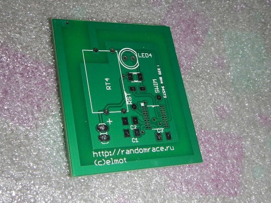
For the first version of the device, Telecontrolli modules were purchased. For transmitters - RT4-433 (later RT14-433). At first it seemed like a good option. To control the modules in the transmitter, one of the cheapest MCUs, STM8S003F3, was used, in an SO-16 package that is convenient for soldering. The circuit is banal - the MCU itself, an obligatory capacitor, a filter capacitor in the power circuit, a radio module, an LED and a resistor to it. About once a second, the transmitter emits about a half-second am-modulated pulse with a frequency of 200 Hz and blinks an LED. This variation of the lighthouse experienced several trials and incarnations.
Self-made lute boards were applied,

Chinese software with seeedstudio;
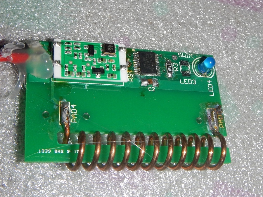
Antennas - springs and printing.
There were also experiments with different LEDs and different currents - for example, there was a thought that abrupt short flashes of an unnatural blue color from inside a transparent container could help to find a container in the forest at night. Radio modules also varied, depending on the market conditions for radio components.
Receiver

For the direction-finding receiver, RRQ14-433 modules from the same Telecontrolli were used. The module has two outputs - the received data and the analogue AGC level, also known as RSSI. On the STM8S903C microcontroller both were set up, but the data output was just in case, the signal on it was ignored by the firmware. The RSSI was polled continuously using the built-in ADC controller. The signal level indication should be twofold - on the one hand, visually, with moderately large figures, visible both during the day and at night. On the other hand, you need to attach the sound - so that you do not have to constantly look at the indicator. Well, Hollywood traditions are like that - it should squeak. The controller was again from the STM8S family, but the other is the STM8S903, equipped with a built-in reference voltage source, which is needed to measure RSSI. A two-digit 7-meter LED indicator was assigned to the indicator role. Classic arduin-like circuits with a mountain of resistors, dynamic indication and other things I didn’t want to fence at all, so the integrated LED driver STP16CP05 went into action. This is a 16-channel shift register with current stabilization at each output, and the current value is set by one resistor for all outputs at once. 16 channels - just 2 digits of 7 segments + decimal points. The indicator itself is simply an indicator of distinct size with a common anode. I made the sound at the last moment from the player headphones that came to hand. Headphones were connected through a resistor (so as not to torment the MK with large currents), to the direct and inverse outputs of the MK timer. Since the radio module requires 5V, it was necessary to raise the supply voltage (2-cell model LiPo at 800mAh) and put the LDO on 5V (it is not on the diagram).

The controller firmware continuously measures the RSSI level, tries to find peaks there at the moment of receiving a radio signal, recalculate them in some “parrots” and bring them to the indicator. The same parrots are converted into the duration of periodic "beeps." At 0 parrots, the direction finder is silent, at 99 it beeps continuously. The transmitter firmware was reworked 100,500 times, mainly due to a distinct recount of the RSSI. I won't show the code from there to anyone, you can't frighten people like that.
First damn.kom
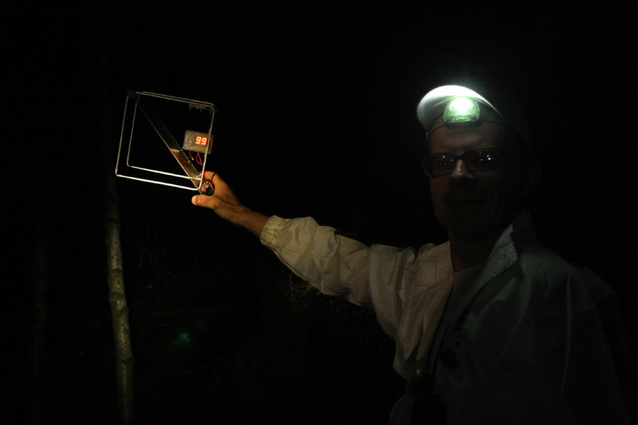
The first tests and competitions using the “find me” system were generally successful; the direction finder allowed us to find a fallen probe a couple of times in the forest. The antenna showed acceptable direction, the probes, as expected, can be heard on the radio. The detection distance in the forest is also within reason. One of the unpleasant discoveries was that the parameters of the transmitter modules rather “walk” from instance to instance - both frequency and power. Different modules squeaked on channels 32-42, with the expected 34. The RSSI level on the receiver also behaved somewhat strange, but some shamanism in the algorithm of the receiver made it possible to see on the indicator some value similar to the signal level of the transmitter in some parrots. In anticipation of the production of the next batch, it suddenly became clear that the key modules for the whole project, the transmitter modules, had risen in price greatly and in general almost disappeared from sale. In anguish, I sadly rummaged in the treasures of aliexpress, without much hope of finding a replacement.
And here.
And here follows a sequel.
References:
Continued: geektimes.ru/post/270170
About the same in English: www.randomrace.ru/2015/gsbc/preparation/transmitter/eng
RandomRace: randomrace.ru (upcoming competitions: www.randomrace.ru/2016/spring )
Sources of all firmware: sourceforge.net/projects/randomracebeacon
GBSC: www.balloonchallenge.org/teams/15
Source: https://habr.com/ru/post/389915/
All Articles