Motor Controller = ATMega8 + L293D + DCDC
As promised, I spread the power part of the robot. She was already in the chassis on combat duty, so no further changes are planned.
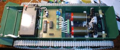
Chassis Assembly
Power Supply.
We also have a lead battery at 12 volts, and the controller needs 5 volts. So I bungled a switching power supply. It was possible, of course, to put some kind of LM7805 (as I have on the breadboard) and to drop the voltage on it, but this is a stupid method. The thing is that the voltage difference LM7805 will belch in the form of heat. So the efficiency of this device will be below 50%, and our battery power. So the only way out is DC-DC conversion. As a controller, I took the time-tested, popular, affordable and cheap MC33063A . I didn’t invent anything and took a typical step-down scheme (Step-Down) from its datasheet.
Power Bridge L293D
This chip is designed to control the DC motor. Contains four powerful amplifiers. If the amplifier is fed to the input 1, then the output is planted at 12 volts, if the input is 0, then the output is planted on the ground. Thus, by feeding combinations 0 and 1 to different inputs, it is possible to put the leads of the engine on tires of different polarities, rotating the slider in different directions.
')

bottom fee

Fee on top.
Boards are made at home by the method of laser iron
Control controller
This ATmega8 is currently the robot's brain controller. But over time, I plan to bring it into a peripheral controller, responsible only for the chassis.
It processes the gear rotation sensors on the gearbox, as well as touch sensors in the front and rear. In addition, i2c and UART buses come out of it, as well as all unused ports. Engines operate on PWM modulation.
Full technical details, schematic diagram, printed circuit board in Sprint-Layout format, pictures in higher resolution.
Also related links:
1) Motor control with PWM modulation
2) Test program for this robot. AVRStudio - Assembler
Chassis Assembly
Power Supply.
We also have a lead battery at 12 volts, and the controller needs 5 volts. So I bungled a switching power supply. It was possible, of course, to put some kind of LM7805 (as I have on the breadboard) and to drop the voltage on it, but this is a stupid method. The thing is that the voltage difference LM7805 will belch in the form of heat. So the efficiency of this device will be below 50%, and our battery power. So the only way out is DC-DC conversion. As a controller, I took the time-tested, popular, affordable and cheap MC33063A . I didn’t invent anything and took a typical step-down scheme (Step-Down) from its datasheet.
Power Bridge L293D
This chip is designed to control the DC motor. Contains four powerful amplifiers. If the amplifier is fed to the input 1, then the output is planted at 12 volts, if the input is 0, then the output is planted on the ground. Thus, by feeding combinations 0 and 1 to different inputs, it is possible to put the leads of the engine on tires of different polarities, rotating the slider in different directions.
')
bottom fee
Fee on top.
Boards are made at home by the method of laser iron
Control controller
This ATmega8 is currently the robot's brain controller. But over time, I plan to bring it into a peripheral controller, responsible only for the chassis.
It processes the gear rotation sensors on the gearbox, as well as touch sensors in the front and rear. In addition, i2c and UART buses come out of it, as well as all unused ports. Engines operate on PWM modulation.
Full technical details, schematic diagram, printed circuit board in Sprint-Layout format, pictures in higher resolution.
Also related links:
1) Motor control with PWM modulation
2) Test program for this robot. AVRStudio - Assembler
Source: https://habr.com/ru/post/38072/
All Articles