Experiment on the construction of a thermoelectric generator based on Peltier elements
Hello, my name is Danil, and I am paranoid. My paranoia is that I am convinced of the imminent arrival of the Great Fox. In what guise this fox will come, it does not matter - if we survive, then, most likely, we will have to start living from scratch. And it is much more fun to live when you have something to charge the batteries in a flashlight and dosimeter. Those who think the same (as well as all the curious), please under the cat (carefully, heavy pictures).

Actually, why the Peltier element? It is much more logical to buy a flashlight with a muscle drive ("ground beetle"), solar panels, or, at worst, build a wind turbine. Previously, I also thought that it was quite possible to get along with the “ground beetle”. But there are a lot of moving parts in it that Uncle Liao made of cheap plastic. The first breakdown in the conditions of the Great Arctic Fox - and you are left without electricity.
Well, you ask why not solar panels? There are no moving parts. I agree, I will answer, but in the conditions of a nuclear or volcanic winter or under a two-meter-high concrete cover of the shelter the sun is not so easy to catch.
')
Windmill? And what area should be his blades so that he could turn even from a weak wind? Moving parts, again. The windmill is suitable for stationary installation when equipping a long-term shelter.
Having pondered these arguments, I am despondent. But soon I stumbled upon the site nepropadu.ru (no advertising, only a link to the source material). I spent two days on it all the time, and in the process I came across an interesting article about a stove-chipmaker from the case of a computer power supply unit with a Peltier element on its side (link at the end of the post). There were many skeptics in the comments, but the author wrote that he was quietly charging the phone from a connected Chinese DC-DC converter ... I caught fire.
For starters, I ordered the same Peltier element from the Chinese on e-Bay (enough for experiments). He cost me 320 rubles. What pleased, it is accelerated, with tracking, but free shipping. Plus, the goods were sent literally an hour after the payment (and it was on Sunday).
While Peltier went, I thought about the design of the future thermoelectric generator, found a suitable radiator with a fan (the ancient processor radiator was perfect), and also dug out a DC-DC converter with a maximum output current of 1 ampere at 5 volts on the Internet.
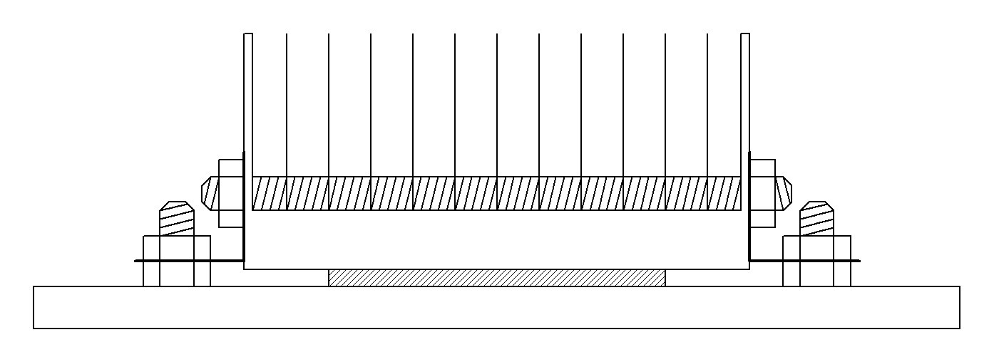
It was not advisable to make a stove-chipper following the example from that article. The metal from which computer hardware is made is very soft, it will “lead” it from the effects of high temperatures, and it will also burn quickly. Therefore, it was decided to make a “removable version” of the generator, which could be mounted on the side of a stationary stove or leaned against a kettle standing on a campfire. And in such conditions not to fry the Peltier element on an open fire, a heat-resistant but heat-conducting gasket was needed. For this, I managed to get a piece of a thick aluminum plate with dimensions of 100x120x5 millimeters.
To press the Peltier element to the aluminum substrate, and, in turn, to press the radiator, I decided to use the children's metal constructor, which I once bought for the needs of robotics.
But here the Peltier element arrived, and it was time for assembly.
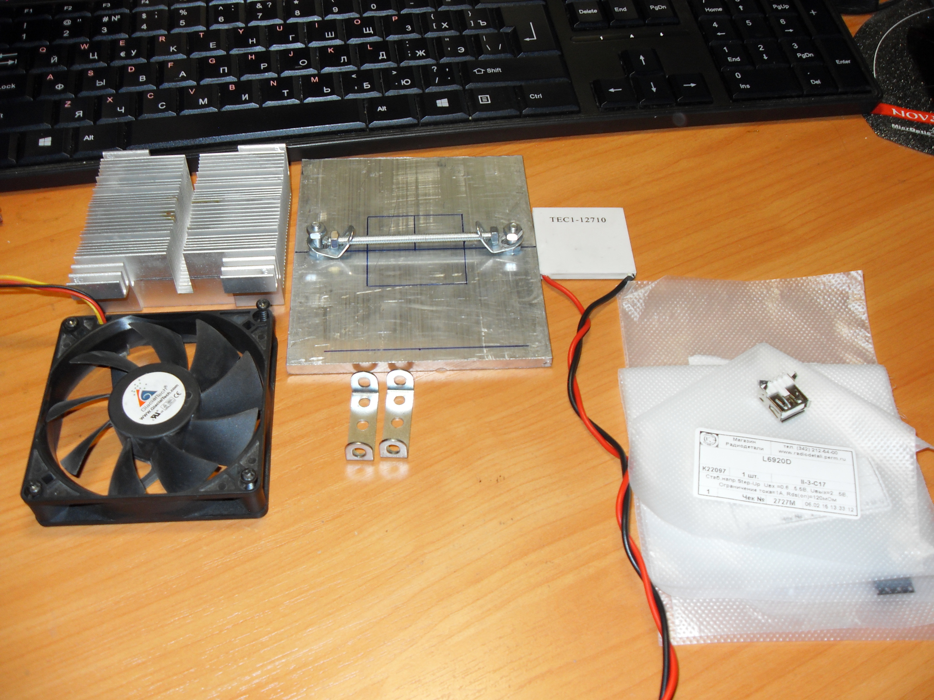
We had a radiator, an aluminum plate, a Peltier element, a handful of radio components, a piece of foiled PCB, and a variety of screws and nuts. I do not remember further.
So, all the components are assembled, you can proceed to assembly.
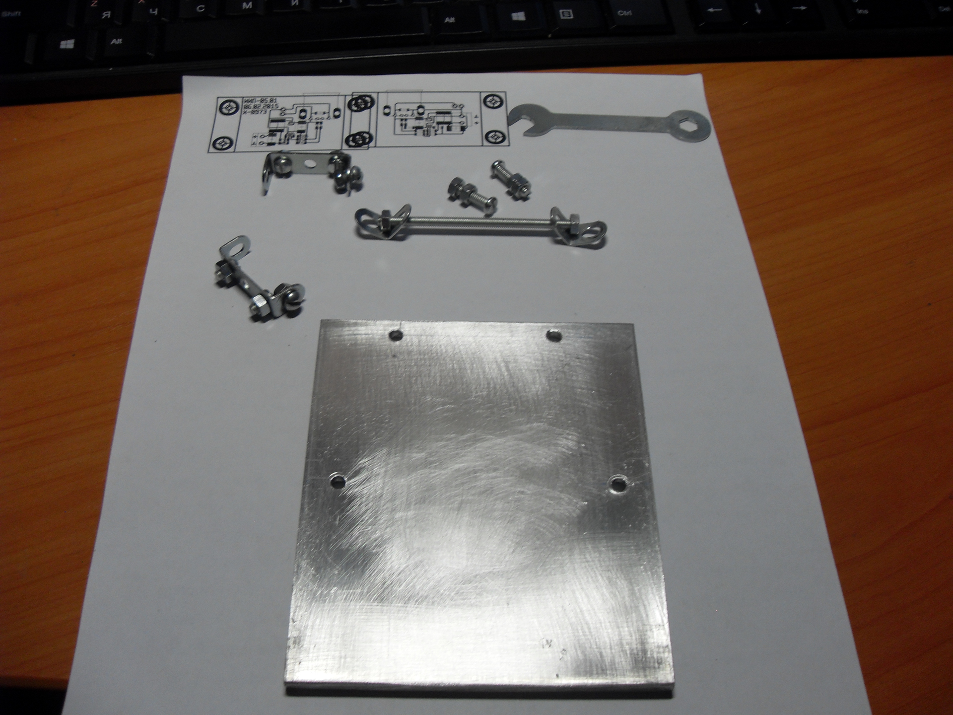
I apologize for the plate that was marked up and drilled in two places - it only occurred to me that it would be nice to photograph the entire assembly process from the very beginning.
The first trouble that lurked me was the 12-volt regular fan on the radiator. Since I am going to produce only 5 volts, and even with a rather small maximum current, this could create a problem.
At first I threw fishing rods into all the radio and computer stores in Perm, but nowhere was there a fan of 80x80 millimeters at 5 volts. And if they were, then the smaller size and current of more than 200 mA, which was too much.
Then I rummaged on Ibeya and found that the fan I needed cost from 300 rubles. But it was pointless to hope for a quick delivery, and therefore I left this option as a backup.
And only after all the searches I guessed to turn on the regular 12-volt fan to the 5-volt voltage source. It turned out that it blows quite well, and at the same time consumes not a very large current. Therefore, I decided to leave it for now, and after conducting the tests, if necessary, order a fan on Ibei.
I marked out the aluminum plate and drilled two holes in it for fastening the radiator and two for the voltage converter board. I made the holes with a diameter of 4 millimeters (for screws from the designer), and from the outside I extended them to 7.5 millimeters to hide the heads of the screws. After that, I filed sharp corners with a file and walked with a large sandpaper over all the surfaces of the plate, and shallow at the place where the Peltier element was pressed.
With this, the processing of the substrate was considered complete and I started to manufacture a voltage converter.
Pulse boost voltage converter is assembled on the IC L6920, which starts to work at an input voltage of 0.8 volts and allows you to remove from its output a fixed voltage of 3.3 or 5 volts, or variable from 1.8 to 5.5 volts.
The circuit diagram of the converter is typical and taken from the datasheet.
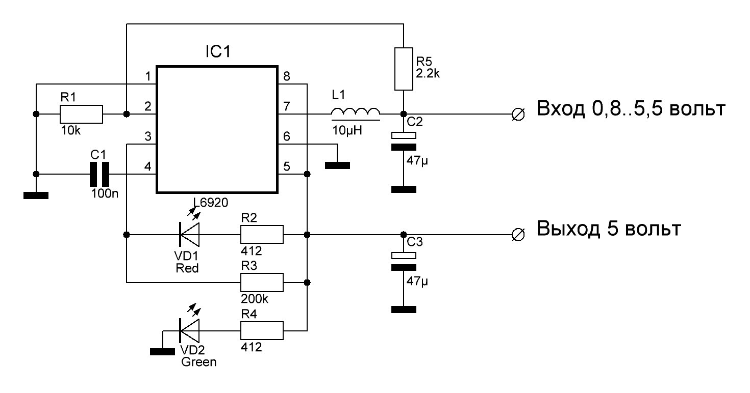
To get 5 volts at the output of the circuit, leg 1 is connected to the common wire. It is also configured to issue a low level on the leg 3 when the input voltage drops below 1.5 volts.
For the circuit, a printed circuit board was divorced, on which it is provided for fastening to the substrate base using all the same parts from the children's designer. I am not worried about overheating of the board, since it has forced cooling by the air flow blown out of the radiator.
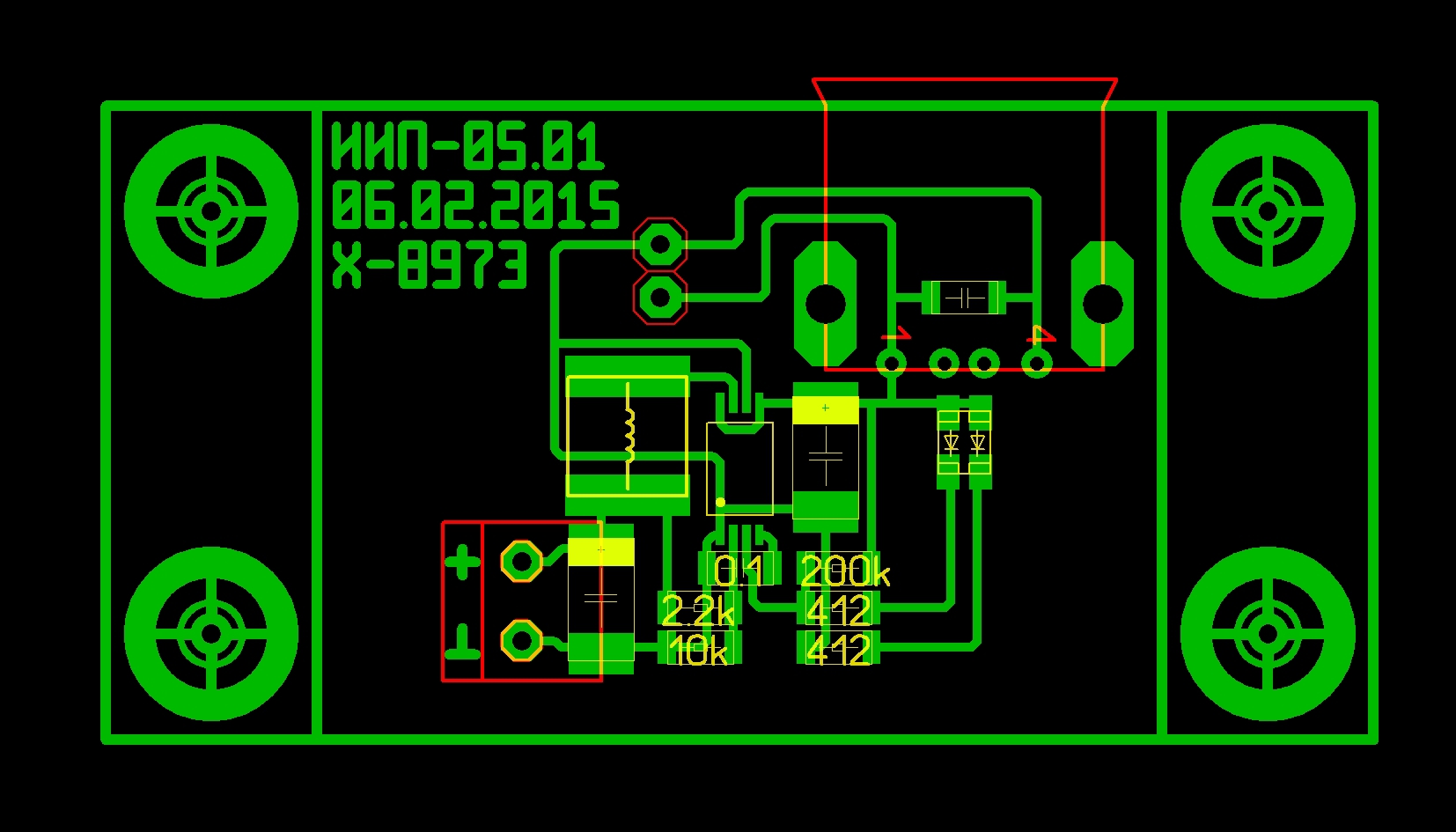
I had to tinker with the macro of the case in which the chip I bought was. The site of the store indicated that it was in the SSOP-8 building. As it turned out, in the standard set of Sprint Layout macros there is no such case. I found a drawing of the SSOP-8 case and made a macro, after which I parted the board. After the test print, it turned out that the microcircuit is somewhat wider, and it does not fit on its pads. Googling a specific chip model (L6920D) led me to the Chip-Deep site, where I learned that the IC with the D index is made in the TSSOP-8 package. Scratching the back of my head, I found a drawing of this case, created a macro and perevezvel fee. Now everything turned out right.
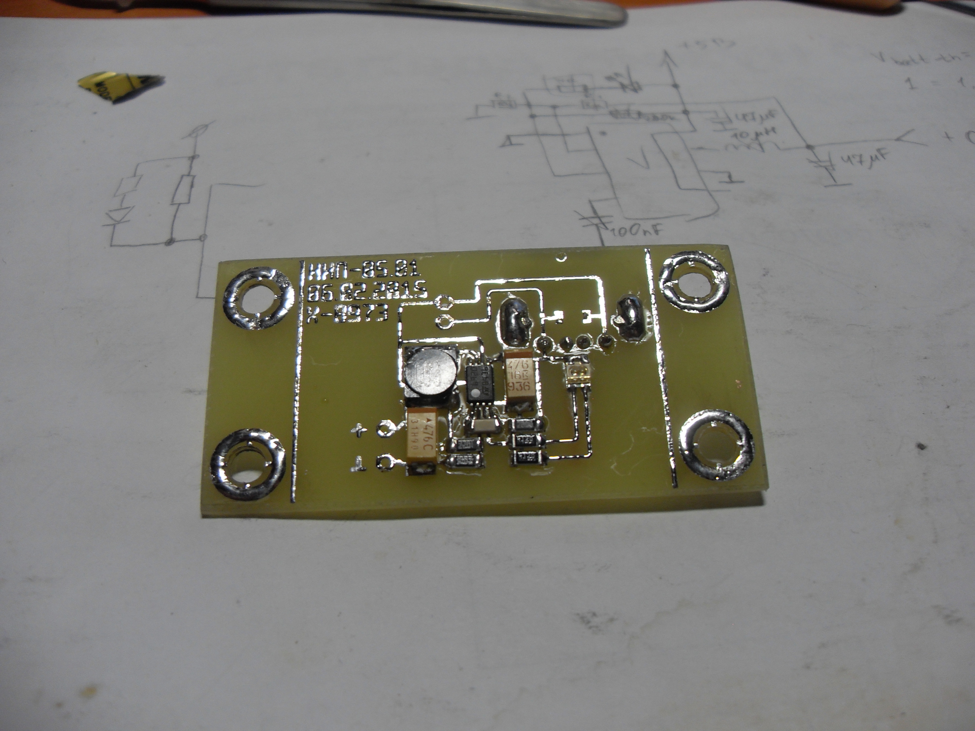
The board is made with the help of LUT and assembled. It turned out that the TSSOP-8 case is very inconvenient to solder without a hairdryer. But we are people grated, FTDI-chips with a pitch of 0.4 mm solder.
Now you can do the installation of the Peltier element and the radiator. The substrate and radiator in places of contact with the element I smeared with thermal paste. Then he pulled the resulting "sandwich" nuts.
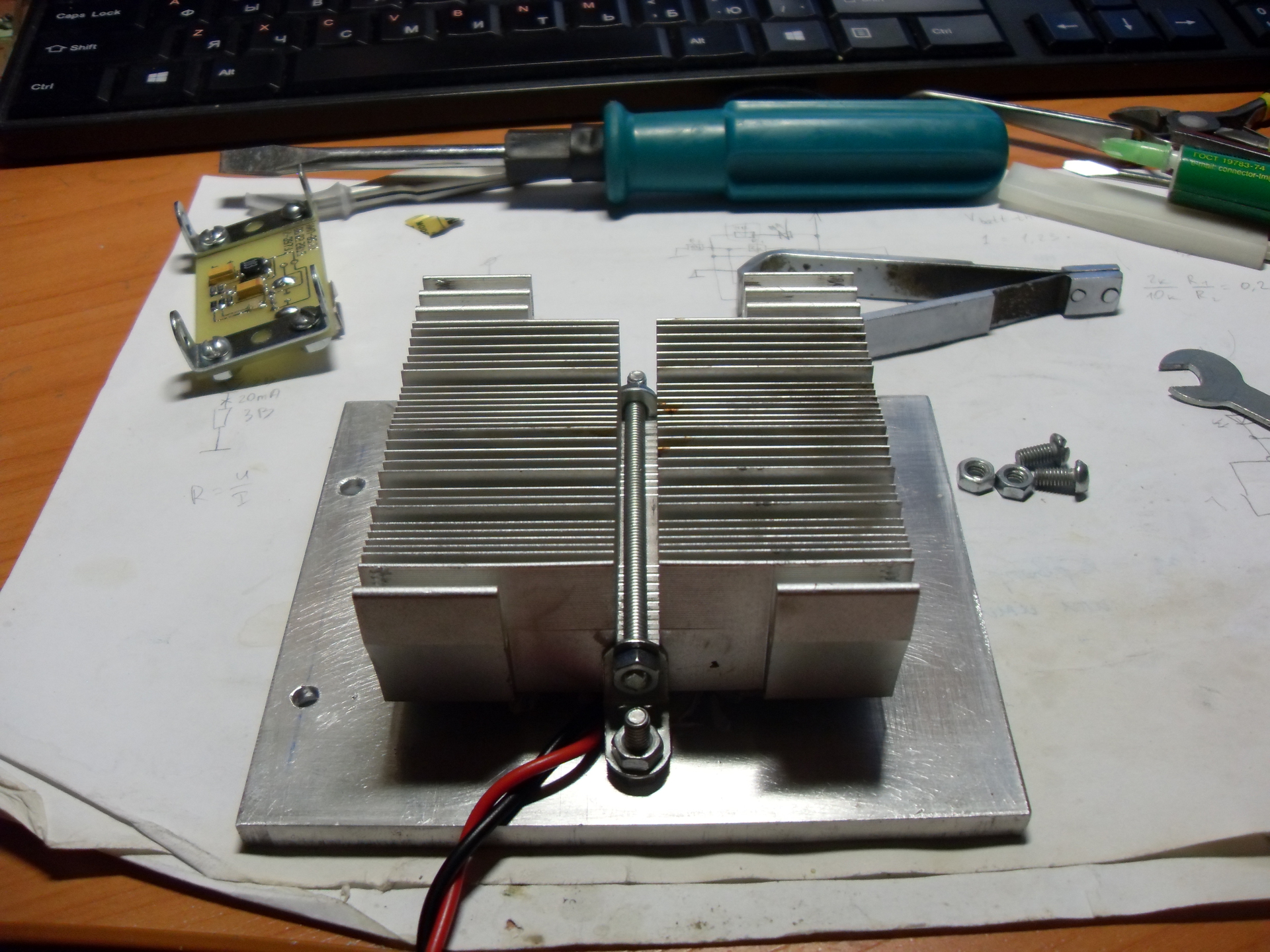
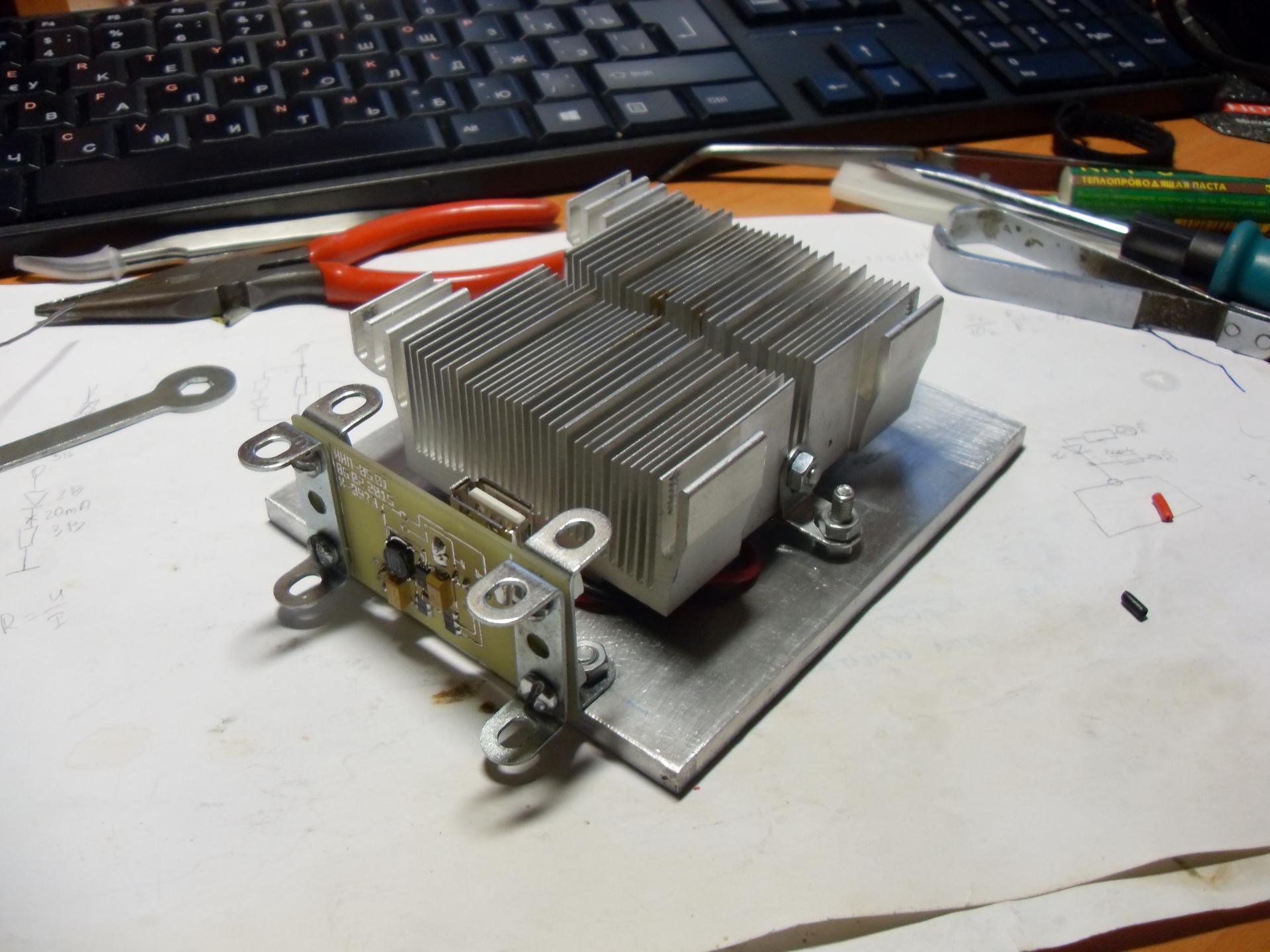
It turned out that the converter board does not fit, rests against the input connector in the radiator, did not slightly calculate. Turned over the mounting brackets, the board hung out, and to protect the elements from mechanical damage added two brackets. Here's what happened:
Now you can check the performance of the generator. I heated it on a gas burner. Fan decided not to install yet.
To begin with, it turned out that I confused the polarity of connecting the element to the converter. Although everything seemed to be correct - the black wire - to the minus, the red - to the plus. However, the generator did not want to work. Then I changed the polarity of the connection element.
The generator started working - at first both LEDs lit up, signaling about the presence of 5 volts at the output and a low voltage at the input, then the red LED went out - the voltage rose above one and a half volts.
To my displeasure, it turned out that without a fan, after a couple of minutes of the system’s operation, the radiator heated up noticeably. So it will not work.
The next day, I walked through the metal market and several computer flea markets, but to my question about the 5-volt fans everywhere they threw up their arms and advised me to go "still to that place" in which I was a couple of minutes ago. In the end, I drove home without a good day.
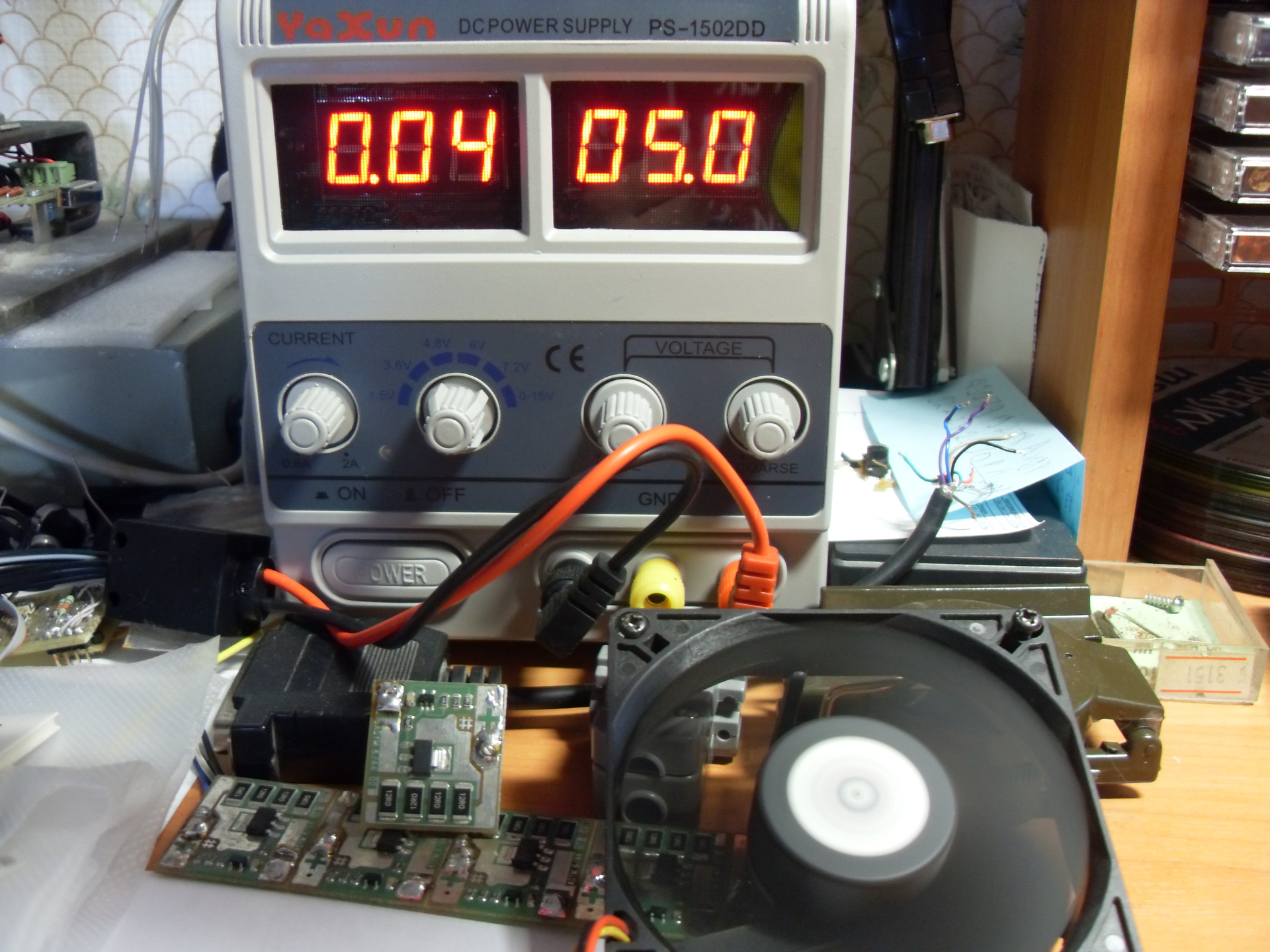
At home, I conducted an experiment on powering a regular 12-volt fan from the output 5-volt converter. I was not pleased with the results - the converter reluctantly turned off the red LED, and the fan twitched weakly for several seconds trying to start up. The air flow from the half-power fan was not enough for normal cooling - the radiator heated up just as quickly, although it didn’t burn the fingers. As a result, I decided to order the fan with Ibei.
Despite the low efficiency of the Peltier element in the generation mode, I still got an intermediate result - when connected to the converter output of a portable battery with a stated charge current of 1000 mA, the generator was able to produce a current of about 600 mA. I think that this current will be enough to charge most gadgets in the conditions of the Great Arctic Fox.
Upon arrival of the fan (Ibei promises mid-March-early April), I’ll check the cooling. Plus, it will be necessary to test the operation of the generator in “combat” conditions - at the stake.
I apologize for the quality of the photos - a photographer from me is none. Link to the article that inspired me: tyts .
Successes!
Research part
Actually, why the Peltier element? It is much more logical to buy a flashlight with a muscle drive ("ground beetle"), solar panels, or, at worst, build a wind turbine. Previously, I also thought that it was quite possible to get along with the “ground beetle”. But there are a lot of moving parts in it that Uncle Liao made of cheap plastic. The first breakdown in the conditions of the Great Arctic Fox - and you are left without electricity.
Well, you ask why not solar panels? There are no moving parts. I agree, I will answer, but in the conditions of a nuclear or volcanic winter or under a two-meter-high concrete cover of the shelter the sun is not so easy to catch.
')
Windmill? And what area should be his blades so that he could turn even from a weak wind? Moving parts, again. The windmill is suitable for stationary installation when equipping a long-term shelter.
Having pondered these arguments, I am despondent. But soon I stumbled upon the site nepropadu.ru (no advertising, only a link to the source material). I spent two days on it all the time, and in the process I came across an interesting article about a stove-chipmaker from the case of a computer power supply unit with a Peltier element on its side (link at the end of the post). There were many skeptics in the comments, but the author wrote that he was quietly charging the phone from a connected Chinese DC-DC converter ... I caught fire.
Design part
For starters, I ordered the same Peltier element from the Chinese on e-Bay (enough for experiments). He cost me 320 rubles. What pleased, it is accelerated, with tracking, but free shipping. Plus, the goods were sent literally an hour after the payment (and it was on Sunday).
While Peltier went, I thought about the design of the future thermoelectric generator, found a suitable radiator with a fan (the ancient processor radiator was perfect), and also dug out a DC-DC converter with a maximum output current of 1 ampere at 5 volts on the Internet.
It was not advisable to make a stove-chipper following the example from that article. The metal from which computer hardware is made is very soft, it will “lead” it from the effects of high temperatures, and it will also burn quickly. Therefore, it was decided to make a “removable version” of the generator, which could be mounted on the side of a stationary stove or leaned against a kettle standing on a campfire. And in such conditions not to fry the Peltier element on an open fire, a heat-resistant but heat-conducting gasket was needed. For this, I managed to get a piece of a thick aluminum plate with dimensions of 100x120x5 millimeters.
To press the Peltier element to the aluminum substrate, and, in turn, to press the radiator, I decided to use the children's metal constructor, which I once bought for the needs of robotics.
But here the Peltier element arrived, and it was time for assembly.
Technological part
We had a radiator, an aluminum plate, a Peltier element, a handful of radio components, a piece of foiled PCB, and a variety of screws and nuts. I do not remember further.
So, all the components are assembled, you can proceed to assembly.
I apologize for the plate that was marked up and drilled in two places - it only occurred to me that it would be nice to photograph the entire assembly process from the very beginning.
The first trouble that lurked me was the 12-volt regular fan on the radiator. Since I am going to produce only 5 volts, and even with a rather small maximum current, this could create a problem.
At first I threw fishing rods into all the radio and computer stores in Perm, but nowhere was there a fan of 80x80 millimeters at 5 volts. And if they were, then the smaller size and current of more than 200 mA, which was too much.
Then I rummaged on Ibeya and found that the fan I needed cost from 300 rubles. But it was pointless to hope for a quick delivery, and therefore I left this option as a backup.
And only after all the searches I guessed to turn on the regular 12-volt fan to the 5-volt voltage source. It turned out that it blows quite well, and at the same time consumes not a very large current. Therefore, I decided to leave it for now, and after conducting the tests, if necessary, order a fan on Ibei.
I marked out the aluminum plate and drilled two holes in it for fastening the radiator and two for the voltage converter board. I made the holes with a diameter of 4 millimeters (for screws from the designer), and from the outside I extended them to 7.5 millimeters to hide the heads of the screws. After that, I filed sharp corners with a file and walked with a large sandpaper over all the surfaces of the plate, and shallow at the place where the Peltier element was pressed.
With this, the processing of the substrate was considered complete and I started to manufacture a voltage converter.
Pulse boost voltage converter is assembled on the IC L6920, which starts to work at an input voltage of 0.8 volts and allows you to remove from its output a fixed voltage of 3.3 or 5 volts, or variable from 1.8 to 5.5 volts.
The circuit diagram of the converter is typical and taken from the datasheet.
To get 5 volts at the output of the circuit, leg 1 is connected to the common wire. It is also configured to issue a low level on the leg 3 when the input voltage drops below 1.5 volts.
For the circuit, a printed circuit board was divorced, on which it is provided for fastening to the substrate base using all the same parts from the children's designer. I am not worried about overheating of the board, since it has forced cooling by the air flow blown out of the radiator.
I had to tinker with the macro of the case in which the chip I bought was. The site of the store indicated that it was in the SSOP-8 building. As it turned out, in the standard set of Sprint Layout macros there is no such case. I found a drawing of the SSOP-8 case and made a macro, after which I parted the board. After the test print, it turned out that the microcircuit is somewhat wider, and it does not fit on its pads. Googling a specific chip model (L6920D) led me to the Chip-Deep site, where I learned that the IC with the D index is made in the TSSOP-8 package. Scratching the back of my head, I found a drawing of this case, created a macro and perevezvel fee. Now everything turned out right.
The board is made with the help of LUT and assembled. It turned out that the TSSOP-8 case is very inconvenient to solder without a hairdryer. But we are people grated, FTDI-chips with a pitch of 0.4 mm solder.
Now you can do the installation of the Peltier element and the radiator. The substrate and radiator in places of contact with the element I smeared with thermal paste. Then he pulled the resulting "sandwich" nuts.
It turned out that the converter board does not fit, rests against the input connector in the radiator, did not slightly calculate. Turned over the mounting brackets, the board hung out, and to protect the elements from mechanical damage added two brackets. Here's what happened:
Now you can check the performance of the generator. I heated it on a gas burner. Fan decided not to install yet.
To begin with, it turned out that I confused the polarity of connecting the element to the converter. Although everything seemed to be correct - the black wire - to the minus, the red - to the plus. However, the generator did not want to work. Then I changed the polarity of the connection element.
The generator started working - at first both LEDs lit up, signaling about the presence of 5 volts at the output and a low voltage at the input, then the red LED went out - the voltage rose above one and a half volts.
To my displeasure, it turned out that without a fan, after a couple of minutes of the system’s operation, the radiator heated up noticeably. So it will not work.
The next day, I walked through the metal market and several computer flea markets, but to my question about the 5-volt fans everywhere they threw up their arms and advised me to go "still to that place" in which I was a couple of minutes ago. In the end, I drove home without a good day.
At home, I conducted an experiment on powering a regular 12-volt fan from the output 5-volt converter. I was not pleased with the results - the converter reluctantly turned off the red LED, and the fan twitched weakly for several seconds trying to start up. The air flow from the half-power fan was not enough for normal cooling - the radiator heated up just as quickly, although it didn’t burn the fingers. As a result, I decided to order the fan with Ibei.
Result
Despite the low efficiency of the Peltier element in the generation mode, I still got an intermediate result - when connected to the converter output of a portable battery with a stated charge current of 1000 mA, the generator was able to produce a current of about 600 mA. I think that this current will be enough to charge most gadgets in the conditions of the Great Arctic Fox.
Upon arrival of the fan (Ibei promises mid-March-early April), I’ll check the cooling. Plus, it will be necessary to test the operation of the generator in “combat” conditions - at the stake.
I apologize for the quality of the photos - a photographer from me is none. Link to the article that inspired me: tyts .
Successes!
Source: https://habr.com/ru/post/376285/
All Articles