How to "bend" the light? Or a brief excursion into the world of fiber optics
Good day, reader! Surely everyone has heard of fiber optics, many have dealt with it in telecommunications, someone even had a fiber-optic cable to the house. In general, this term is well known; and the essence of the issue - the transmission of light at a distance along a thin fiber - is generally understood. But I suggest a little deeper into this technology, which in many ways changed the world. In this post I will try to explain the essence of fiber optics in a simple and understandable language, how it works - at the level of simple physical understanding, with simplifications and examples, without scary formulas. In other words, "on the fingers." If interested, then welcome under cat. Caution : a lot of text, there are pictures.
By the will of fate, it so happened that my education, and then my professional activity, was tightly connected with optical fiber and lasers. Having worked in telecom for some time, and then going over to the field of scientific development and measurements, I had the opportunity to notice that not everyone is familiar with optical fiber at the level of deep understanding, even among tech-lasers and telecoms. Those who are engaged in telecom, most of them perceive the fiber at the level of “patchcord” or cable. For them it is a patch cord or an abstract communication line. Yes, with attenuation, dispersion, welding and reflectograms, but only with a superficial understanding of the physical principle of operation. Of course, this is not at all bad, just the features of their work. In any case, the desire to write a popular science article on the very essence of fiber optics has arisen repeatedly, especially since education and experience allow it to be done: everything that is written in this article is not only “material from textbooks”, but also my personal experience. On the one hand, I would like to dwell on many points in detail, but on the other hand, the article will turn out to be too large. It was decided to do this: this article is introductory and overview. If the public has an interest, there will be a series of posts devoted to the most interesting issues in the vast fiber-optic topic. I hope it will be interesting. So let's go!
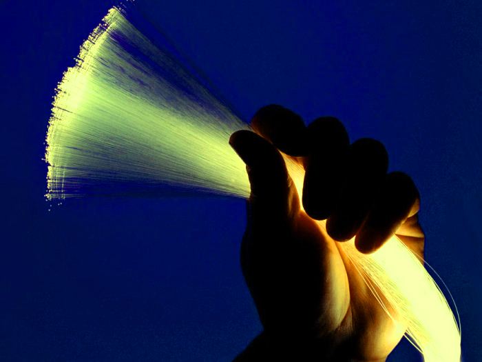
The first thought that arose in my then childish brain, when I first saw such a light guide lamp , was “How does it work !?”. At school, we were taught that light in a homogeneous medium propagates rectilinearly. How to bend the light? The answer learned a little later. We all heard about the effect of total internal reflection, the so-called. Air defense. If the light comes out of a more dense optical medium (glass) into a less dense (air), n glass> n of air, then at a certain angle of incidence the light may not come out, but will be reflected back. All this is well known to us from the school. Behind this phenomenon are quite thick equations of wave propagation of light and volume theory. But we do not need it now, it is enough to know what it is. Air defense in everyday life was watched by almost everyone. At least, the one who dive with a mask under the water. From the water we can see everything that is right above us, but at some periphery we see the mirror surface of the water and do not see what is above it - this is air defense.
')

Now imagine that we have a sheet of glass in the air. If you light him at the end with a laser pointer at a small angle to the plane of the surface, then its light, having repeatedly reflected, will come out from the other side of this glass - this works the air defense phenomenon. Now take a glass rod - the effect will be the same. In this case, the light is not limited in one, but already in two planes, of course, if the angle of incidence of the light does not exceed the angle of air defense.
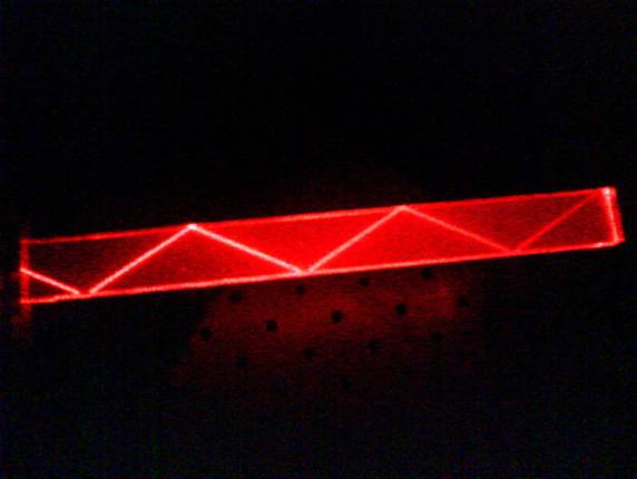
But if we replace the glass rod with a transparent fishing line, then the light will propagate in it, but it can already be “bent”. Of course, as long as the bending radius is large enough. When the bending radius becomes small, the light will come out of the fishing line at this place, since the angle of incidence of light on the surface of the fishing line will be greater than the angle of air defense. Note that the fishing line does not have a mirror coating, the light is held in it by itself. Similarly, optical fibers work. The light spreads in them until the law of air defense is violated and the light does not come out of the light conductor. Optical fiber, in essence, is the same line in a decorative lamp, but has a more complex structure.
In general, optical fibers there are a huge number of species, differing in shape, size, material, coating, properties, applications, etc. A review and comparison of various types of fibers is a topic for a separate huge article. However, all these fibers constructively combine one thing: they have a light-carrying core (core) with a larger refractive index and a cladding (cladding) with a smaller refractive index. Due to this, the effect of air defense is achieved. Regarding fiber sizes, depending on the design and application, they can be from 50 μm to 1 mm or more in diameter (meaning the fiber itself without protective shells). The imposition of various protective shells increases the diameter of the fiber at times. In this article I will consider only the simplest and most common types of fibers used in telecommunications. If there is interest, let's talk about others.
Telecommunication fibers, and many others, in 99.9% of cases are made of pure quartz glass. Chemical formula SiO2. Window glasses are made of it, but with impurities that block UV radiation: Na2C03, K2CO3, CaC03. Wikipedia on silicon dioxide is enough information. Yes, flexible optical fibers are really made of glass - some never believed me. The stereotype that the glass does not bend, but it pricks and beats into human heads firmly.
It is well known that glass has an amorphous structure, which means it does not have a fixed melting point, like crystalline substances. When heated, the glass softens and becomes viscous, and a “string” can be easily pulled out of it. However, such a fiber, although it bends, is very fragile, since microcracks quickly form on its surface, which destroy the fiber as the stress on their surface increases during bending. Freshly fiber is immediately covered with a plastic film that protects against microcracks. But first things first.
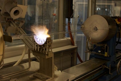
I will describe the "classical" scheme for the manufacture of telecommunication single-mode fibers with deposition from the gas phase. First, a glass tube is taken about a meter long or a little more and a few centimeters thick. Inside it is hollow. Its internal diameter determines the thickness of the light-bearing core. The main difference of such glass is a very high degree of purification from impurities and OH groups. This is necessary so that the fiber has maximum transparency. The pipe is laid on the machine and begins to rotate around its axis, gradually warming up with a burner with a temperature of 1200-1500 ° C. From the end, a mixture of O2, SiCl4, GeCl4, etc. gases is blown into the pipe under pressure, provided by the technology.
Germanium dioxide and SiO2 epitaxy occurs on the surface of the hot glass preform pipe. Germanium dioxide increases the refractive index of pure quartz and has little effect on transparency. The desired profile of the refractive index of the core is grown from the gas phase by controlling the ratio of gases supplied to the workpiece.

After increasing the layer of the desired thickness, the temperature of the burner increases. The glass softens stronger and the cavity of the core, through which the gas has been blown, gradually collapses under the action of the surface tension force. It looks like this:

And this is how the blanks are ready for drawing:

It turns out a solid glass rod with an increased refractive index inside - this is the future light-guiding core. Then the rod is installed vertically and the burner heats its lower end, softening it more strongly. A seed is brought to the workpiece, after which the stretching process begins. Who ever glued glue a la "Moment" perfectly represents what it looks like.
Tower layout for fiber optic hoods:

The fiber extraction unit occupies 2-3 floors:

And this is what the drawn out fiber immediately after the stove looks like.
Modern towers for fiber extraction are hung with sensors that constantly measure its thickness, eccentricity and other deviations.
Immediately after drawing on the same tower, the fiber is coated with a protective polymer and wound onto coils. Protective polymer protects the glass from the appearance of microcracks and external damage. The resulting fiber in the polymer shell has a thickness of 0.25-0.4 mm, depending on the thickness of the coating layer. Outwardly, practically does not differ from ordinary fishing line. Often the fiber cladding is dyed in different colors so that they are easy to distinguish when mounted. Many have a question about the strength of the fiber. It seems that breaking it should be very easy, because glass is fragile. In fact, it is not. Of course, you can break it with your bare hands by applying a certain effort. But to break the line of similar thickness is somewhat easier. Optical fiber is really quite durable to tear. But it does not tolerate excesses - otherwise I would have caught fish for them a long time ago. It can easily be wound on a finger or even a thin pencil, but tie it in a knot, even without tightening it, it will not work - it will break off.
The manufacturing process of all quartz optical fibers is approximately the same. But then their fate may vary greatly depending on the properties. Telecommunication fibers are sent to another factory or to a nearby workshop, where they are placed in cables of various designs: from the simplest cord of an optical patch cord or pigtail to thicker cables for underwater intercontinental location. Feel the difference:
Single Mode Pigtails:

Fiber optic cable for subsea installation:
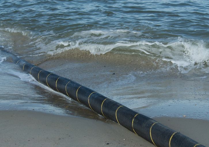
Of course, such a cable contains not one fiber, but several dozen, or even hundreds. About laying such cables, if the memory doesn’t change me, it was once written on Habré.
As for fiber manufacturers, there are a lot of them. Giants in the production of telecommunications fibers Fujikura and Corning (which make Gorilla Glass). They produce most of the telecommunication fibers. It is also worth noting such manufacturers as Draka, Fibercore, Nufern, Samsung, Ceramoptec, OFS, NKT Photonics and others. Even in Russia, optical fibers are produced, for example, at the St. Petersburg enterprise NITIOM, etc. Unfortunately, there is no talk about serious mass production of high-quality cheap fibers for telecom in Russia - under the onslaught of cheap quality products from Chinese, Japanese, American and European manufacturers, our enterprises do not stand competition. The fiber that we produce is mainly specialized and narrow-profile.
But optical cables, by the way, are produced very intensively in Russia. But I will not speak here about the process of manufacturing fiber optic cables of various designs, since this is a topic for a separate article. If it is interesting, I will reveal it too.
Now, probably the most interesting. We talked about the manufacturing process and a little about the physical principles of work. Well, now we will understand why, in fact, fiber optics is now the basis of modern telecommunications.
We can generate traffic. The development of semiconductor technology has led to a huge increase in computing power of computers. This could not but lead to an increase in the volume of information generated. But little sense from the huge deposits of information, if it can not be quickly transferred. How to transfer a large amount of information to a distance quickly? That's right, you need to take a high-speed communication channel. And here, at some point in its technological development, humankind found itself in a problem. By a certain time, it came to the realization that there are not enough high-speed communication channels. And if they are theoretically, then prohibitively expensive and complex. Of course, it was all a long time ago when the computers were big. But even then the question of expanding channels arose more and more clearly. By 60-70m, it already required a solution, despite the fact that the amount of information generated by computers was insignificant compared to the traffic that exuded telephone networks, television and radio. It's all different now.
We know that information can be transmitted by electromagnetic waves. They can spread both in the air (vacuum) and along the wires - copper coaxial or twisted. It is quite obvious that whatever information is analog or digital, the speed of its transmission depends on the frequency of the electromagnetic wave carrying this information. The higher the carrier frequency, the faster the information transfer rate may be. Thus, it is quite obvious that in order to increase the transmission speed in any medium, it is necessary to fundamentally increase the carrier frequency. It is important.
Now we recall the course of physics from school - a lesson about electromagnetic waves. Imagine the frequency scale of electromagnetic waves:

Submitted? Radio waves and microwaves - infrared light - visible light - ultraviolet - x-rays - gamma radiation. Picture from a textbook on physics. Far infrared light is conventionally bordered by the radio range, and near infrared is already the optical range, which also includes visible light. What frequencies does the radio work on? Hundreds of megahertz. And WiFi, Bluetooth, etc.? A few gigahertz. You can further increase the frequency of the radio signal. But a high-frequency generator, especially at high power required for transmission over long distances, is a nontrivial and very complex thing. Semiconductor electronics has a "ceiling" of operating frequencies. This is a fundamental limitation - the pn-transition simply cannot work faster. The fastest semiconductor transistor operates at a frequency of about 1 THz at a temperature of 4.7K. And in the 60s they never dreamed of such a frequency. Therefore, in the radio frequency band, the frequency will no longer be increased. We need a new source of high-frequency electromagnetic waves with a much higher frequency.
What available sources of sufficiently high-frequency electromagnetic waves can be offered? If you look at the picture above, you can see that infrared and visible light go further along the frequency scale from radio waves. We can generate light, somehow manage it too. Already good. In 1960, the world's first laser appears. A laser is a generator of high-frequency electromagnetic waves with a certain frequency, light waves. Unlike a light bulb, a laser generates a very narrow spectrum, almost one wavelength. And he has coherent radiation. Therefore, the laser is suitable for the role of a carrier frequency generator for high-speed data transmission. The frequencies of the near IR - hundreds of THz - the frequency is 4-5 orders higher than traditional radio waves. The source of the carrier of high-frequency electromagnetic waves appeared, and the prospect of the development of high-speed data transmission arose.
The first gas laser showed the theoretical possibility of creating a coherent source of electromagnetic waves of light frequency. The appearance and development of other types of lasers is a matter of time, for the principles of their work have become widely known. But the question of transmitting such high-frequency electromagnetic radiation over long distances has become extremely relevant. Light lives according to the laws of optics, unlike radio waves, which means it was necessary to find an analogue of coaxial cables, only for light.
Already in 1966, researchers Kao and Hokam from the STC Laboratory presented the first optical light guides in the form of filaments made of ordinary glass. The attenuation of light in them was about 1000 dB / km, which made it impossible to transmit any signal over long distances. Such losses were caused by the presence of a large amount of impurities in the glass.
In the 1970s, Corning produced optical fibers that had attenuation of about 20 dB / km. Now such values seem incompatible with data transmission, but then they seemed acceptable for the organization of communication via fiber. At about the same time, sufficiently compact semiconductor gallium arsenide lasers were invented. From 1975 to 1980 the first commercial communication line was implemented at a speed of 45 Mbit / s. And in 1988 the first transatlantic fiber-optic cable was laid.
Any fibers, incl. Telecommunications are divided into two types: single mode and multimode. Despite not a huge variety of species, each of them belongs to either one or another type. How do they differ - we will understand. Historically, the first commercial fibers, due to the imperfection of the manufacturing technology, had a rather thick light-carrying core. It could spread several light modes, so they were called multimode. Let's "on the fingers" understand what light fashion is.
Light is an electromagnetic wave. The laser light is a coherent wave, which means it can interfere. It can also interfere in the fiber, i.e. fiber. Contrary to popular belief, light from a laser is introduced into the fiber not in the form of an absolutely perfect parallel narrow beam, but with a certain angular divergence. And it is not so small. And it is impossible to form a perfect parallel beam - there is always some divergence. Imagine that such a beam was introduced into the fiber with some divergence. The beam, propagating in the core, at some point will begin to reflect from the upper and lower boundaries of the core and the substrate. The reflected parts of the beam will form interference because they are coherent. Interference, as is known, is the alternation of light and dark stripes, the discrete spatial structure of the redistribution of light intensity. It turns out that in a limited space, when its size is comparable to the wavelength of light, the light beam propagating in this space splits into several discrete spatial structures, which are called light modes.
Complicated? Not really. Light mode - this is just a standing light wave that occurs in the cross section of the fiber. What is a standing wave, I think, no need to explain. If a standing wave in the cross section of the fiber has one antinode, then this is the first mode, if 2 is the second, 3 is the third, and so on. Modes are stable discrete spatial-energy structures of the distribution of the electromagnetic field of a light wave, caused by the occurrence of interference on the reflections of light from the walls of the fiber. A mode in a fiber occurs only if light is introduced into the fiber at a certain angle. The angle of light input into the fiber, at which a certain light mode is formed, is called a mode angle. Light introduced not under the mode angle will pump its energy into the nearest mode or radiate out. In other words, the light in a light guide can propagate only at certain angles — modal. At these angles, standing waves appear in the fiber section.
By reducing the size of the light-carrying core, you can achieve single-mode operation of the fiber. In this case, a standing wave in it has only one antinode.
In thick fibers, the size of the core of which significantly exceeds the wavelength of light, the number of modes is very large. Such fibers are called ordinary fibers; the laws of ray optics can be applied to them with some reservation. Fibers with a relatively small number of modes, as well as single-mode fibers, are usually called waveguides, and their calculations must take into account the wave properties of light. Optical waveguides are analogous to coaxial cables for light.
As already mentioned, historically the first were multimode fibers. They have a significant drawback, limiting the transmission speed and range: intermode dispersion.

The first multimode waveguides, which had a stepped refractive index profile (Fig. A), also had a significant temporal broadening of the light pulse and distorted its shape. The figure clearly shows the mechanism of this process. The light pulse introduced into the fiber decayed into discrete modes, however, due to different angles, each mode had a different optical path, and therefore a different propagation time. In practice, this led to the fact that the light pulse stretched in time and could overlap with the next one following it. This meant a lot of mistakes and loss of information.
Subsequently, the technology made it possible to manufacture multimode waveguides with a gradient index of the refractive index (Fig. B). This led to a decrease in intermode dispersion and an increase in the transmission rate, but in principle did not solve the problem.
Significantly increase the speed and range of transmission allowed single-mode fiber. If there are no extraneous modes, then there is no intermode dispersion, the light pulse is not broadened.

Today in the course of both types of fiber, however, single-mode is much more common. For the price it does not exceed multimode. Standard singlemode is ubiquitous. A modern telecom man thinks about the type of fiber very rarely. Default is single mode everywhere. Of course, there are also specific types of fibers used in telecommunications: non-zero dispersion, non-zero offset dispersion, negative dispersion, active doped fibers, etc., but it is not possible to consider them within this article.
It was already mentioned that the first glass fibers had attenuation of about 1000 dB / km, and the first commercial fibers - about 20 dB / km. Now attenuation is much less. But let's understand this deeper. Attenuation in the fiber depends not only on the purity of the material and the quality of manufacture of the waveguide, but also on the wavelength of light.
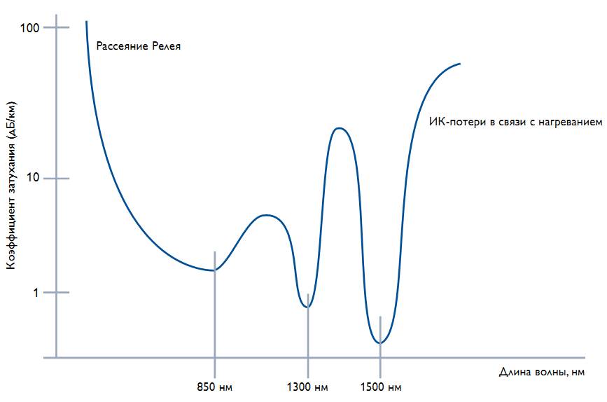
UPD: A slightly less visual, but more correct attenuation graph (thanks to enclis ) looks like this:

The figure shows the attenuation curve of light in a quartz fiber. From the graph, 3 attenuation minima - transparency windows - are clearly visible. Historically, the first transmittance window at 850nm is still used in multimode fibers for communication over short distances. The attenuation in it is 3-5 dB / km. For comparison: imagine a piece of window glass 1 km thick. In it, the light will attenuate only 2 times. The second transparency window at 1300-1310nm has a damping level of 0.3-0.4dB / km. The third window, the most popular today, with a wavelength of 1500-1550nm, has attenuation of about 0.22-0.3dB / km.A piece of glass 10km thick will weaken the light by only 2 times. Light with wavelengths shorter than 850nm is rather actively scattered, longer than 1650nm is already strongly absorbed by glass. The absorption peaks between the transparency windows are due to the presence of an impurity and OH groups, the vibrational levels of which absorb light well in these ranges. It should be noted that this curve for modern fibers looks even more positive: we learned how to make fibers with a low content of OH and impurities, therefore there is practically no absorption peak between 1300 and 1500 nm; it became possible to organize multichannel transmission systems with spectral densification over the entire wavelength range from 1270 to 1610nm (CWDM systems). Today, 850nm is usually used in multimode lines with a transmission range of up to 3-5km,all other wavelengths are for single-mode fibers with long-distance transmission.
Another important factor, in addition to attenuation, limiting the range and speed of transmission is chromatic dispersion. No, it is not intermode, peculiar to multimode fibers. Chromatic dispersion is orders of magnitude weaker and has a different nature, but it has to be taken into account when calculating long communication lines, especially with speeds of more than 10 Gbit / s. Remember how white light in a glass prism unfolds into a rainbow ? This is chromatic dispersion - the dependence of the refractive index on the wavelength. In other words, each wavelength of light has its own, different from others, propagation velocity. In fiber links, chromatic dispersion leads to a broadening of the light pulse in time. Any laser is not ideal: it emits not one wavelength, but a whole spectrum of waves, even if it is narrow. Those.Each light pulse emitted by a laser incorporates a certain set of different wavelengths. Each of these waves, propagating through the fiber, has its own speed, different from the others. This leads to the fact that at the exit from the fiber the impulse expands with time. Of course, this effect is much less noticeable than the intermode dispersion, but the result is the same - the broadening of the pulse and the loss of information, errors. The chromatic broadening of the pulse depends on the width of the laser spectrum, the transmission distance and the fiber dispersion coefficient. Standard fiber has a chromatic dispersion of 18 ps / (nm * km) for a wavelength of 1550nm. Since in most cases fiber optic links consist of standard fiber, dispersion compensation has to be made approximately every 70–90 km (true for 10Gbit / s links organized by a pair of transceivers).
I do not consider other types of dispersion, they are much less critical for fiber-optic communication lines, however, those interested can familiarize themselves with its types here .
Usually the communication channel is organized in two fibers. In the understanding of telecommuters, in most cases any communication channel is duplex, i.e. there is a simultaneous transmission from node A to B and from B to A. It is usually carried out via two fibers: from the transmitter (Tx) at point A to the receiver (Rx) of node B and from Tx B to Rx A. Light is not a streetcar on rails, it is immaterial and can spread along one fiber in both directions at the same time with almost no interaction. The only question is how to divide the transmitted and the received signal at the input and output. There are ways, and several of them. In general, each fiber in a cable has a huge potential for information transfer, but the amount of fibers in any cable is finite. Use a pair of fibers to organize one duplex channel, and even if there is a low speed in it - the top of the waste.
Of course, you can lay more cables - the fiber-optic cable itself is not so expensive - its coordination and laying is expensive. Extensively expanding the bandwidth and the number of channels by laying new cables is stupid if we have only one channel for a couple of fibers. It is necessary to increase the number of channels in a pair of fibers (or even in a single fiber) in order to make cable and fiber use more profitable. How can I push the maximum amount of information into the fiber? To begin with, it is necessary to aggregate information flows - by electrical methods. If you think that when you talk with a person in another country or city on Skype or watch an online movie from a remote hosting service, you are allocated a separate pair of fibers for the entire session, you are greatly mistaken.In fact, your traffic is divided into packets and repeatedly combined with the traffic of other users and in the form of a tremendous digital container is sent over the fiber. On the receiving side, this container is disassembled and your little traffic bag is sent further to the addressee. Channel aggregation is a great way to increase the efficiency of using a line, because instead of a large number of “thin” channels on a heap of fibers, you can transfer one “thick” channel with just one pair. By the way, the first aggregation node can be considered your home WiFi router, which collects traffic from your phones, laptops, PCs, tablets, etc. into one information stream. and sends in the direction of the provider.On the receiving side, this container is disassembled and your little traffic bag is sent further to the addressee. Channel aggregation is a great way to increase the efficiency of using a line, because instead of a large number of “thin” channels on a heap of fibers, you can transfer one “thick” channel with just one pair. By the way, the first aggregation node can be considered your home WiFi router, which collects traffic from your phones, laptops, PCs, tablets, etc. into one information stream. and sends in the direction of the provider.On the receiving side, this container is disassembled and your little traffic bag is sent further to the addressee. Channel aggregation is a great way to increase the efficiency of using a line, because instead of a large number of “thin” channels on a heap of fibers, you can transfer one “thick” channel with just one pair. By the way, the first aggregation node can be considered your home WiFi router, which collects traffic from your phones, laptops, PCs, tablets, etc. into one information stream. and sends in the direction of the provider.The first aggregation node can be considered your home WiFi router, which collects traffic from your phones, laptops, PCs, tablets, etc. into one information stream. and sends in the direction of the provider.The first aggregation node can be considered your home WiFi router, which collects traffic from your phones, laptops, PCs, tablets, etc. into one information stream. and sends in the direction of the provider.
But if we already have a lot of aggregated “thick” channels, and there are only a couple of free fibers, then we have to organize another type of compaction - by optical methods, or spectral compaction. Its essence lies in the fact that for each “thick” channel a certain frequency is allocated (the wavelength of light, its own laser) from a set of standardized wavelengths. It is this wavelength modulated by the signal. There are several such modulated carrier waves, they are multiplexed into one fiber and sent as a set in the form of such a set. Convenient and efficient. Allocate CWDM technology ( coarse wavelength division multiplexing ), which allows to organize up to 16 channels on a pair of fibers or up to 8 one by one, and DWDM ( dense wavelength division multiplexing)), having a much greater potential in compaction. The essence of CWDM and DWDM is similar, the main difference is only in the frequency plan. On the links given there is an excellent description of both technologies.
Transcontinental and trunk communication channels have a very high degree of aggregation and spectral compaction . Networks of the level of cities and regions are usually limited to aggregation up to 10-40 Gbit / s per channel with multiplexing up to 10-15 channels and costing ordinary transceivers, but there are exceptions. But the network areas rarely go beyond the simple CWDM technology with speeds up to 10 Gbit / s per channel. As for houses, the wiring to the entrance is most often carried out by a copper cable. Optics enter the access router, and a twisted pair diverges from it into the apartments.
No matter how good the fibers are, the attenuation, however small, is present. Light in the fiber is attenuated. After a distance of 80 km, the light will attenuate by approximately 20 dB - 100 times, this is without taking into account losses on connections, welding, inhomogeneities, multiplexers, etc. For the organization of long lines of communication it is necessary to use amplifiers and signal regenerators. The regenerator performs a full optoelectronic conversion, waveform recovery and resynchronization ( 3R regeneration) with subsequent re-radiation into the fiber. They are expensive and very complex. Amplifiers, unlike 3R converters, only amplify the signal, increasing their amplitude, but they are much simpler and cheaper. Another advantage of them: they strengthen all channels at once.
Amplifiers are mainly applied to DWDM systems. An optical amplifier is not an ordinary radio frequency opamp on a microcircuit, because semiconductor electronics does not work here. An optical amplifier, in fact, is a laser that does not have a resonator region and operates in one pass. There are several different types of such amplifiers, but the most common are EDFA, amplifiers on erbium doped fiber. In short, the active medium is formed in the core of the doped fiber under the action of pumping at 980 or 1490 nm. Signal radiation entering the active medium causes the induced emission of photons, which add up to the signal, amplifying it. The principle of the laser. EDFAs introduce noise, which limits the number of amplification stages used and requires consideration when calculating and designing communication lines with amplification.
I have already mentioned the dispersion compensation. Dispersion distortions of the signal accumulate, distorting and expanding the signal pulses. Dispersion correction when designing extended communication lines is performed using dispersion compensation modules, DCM ( dispersion compensation module). Usually they do not consider a temporary expansion of the pulse, but they say that it is necessary, for example, to “compensate for 40km of fiber”.
Preliminary calculation of fiber optic lines is reduced to taking into account all attenuations along the path from Tx to Rx and in the opposite direction, taking into account chromatic dispersion, taking into account the noise amplifiers. In the simplest case, if amplification and dispersion compensation are not required, only attenuation from Tx to Rx is calculated, the technological margin of 3-6 dB is added to the “aging” of the line and compared with the optical budget of a pair of transceivers (transceiver modules), on which connection If the budget of transceivers exceeds the calculated value - they can be used to organize the communication line. If the calculated value is greater, you will have to select more “powerful” or sensitive transceivers or look for alternative solutions, up to switching to amplified wavelengths and installing amplifiers.
The topic of designing and calculating communication lines in optics is very broad and full of nuances; more than one article can be devoted to it. If the reader is interested in these questions, I will try to answer them in future publications and comments.
I did not elaborate on spectral compaction and multiplexers, measuring equipment, fiber welding and cable manufacturing, amplifier modeling, I didn’t talk about the element base and much more I would like to tell you about. Unfortunately, all together it does not fit in one article.
The publication turned out a little chaotic and superficial. It is of an exploratory nature in order to understand which of the areas represented in it are of most interest to readers.
By the will of fate, it so happened that my education, and then my professional activity, was tightly connected with optical fiber and lasers. Having worked in telecom for some time, and then going over to the field of scientific development and measurements, I had the opportunity to notice that not everyone is familiar with optical fiber at the level of deep understanding, even among tech-lasers and telecoms. Those who are engaged in telecom, most of them perceive the fiber at the level of “patchcord” or cable. For them it is a patch cord or an abstract communication line. Yes, with attenuation, dispersion, welding and reflectograms, but only with a superficial understanding of the physical principle of operation. Of course, this is not at all bad, just the features of their work. In any case, the desire to write a popular science article on the very essence of fiber optics has arisen repeatedly, especially since education and experience allow it to be done: everything that is written in this article is not only “material from textbooks”, but also my personal experience. On the one hand, I would like to dwell on many points in detail, but on the other hand, the article will turn out to be too large. It was decided to do this: this article is introductory and overview. If the public has an interest, there will be a series of posts devoted to the most interesting issues in the vast fiber-optic topic. I hope it will be interesting. So let's go!
How it works?
The first thought that arose in my then childish brain, when I first saw such a light guide lamp , was “How does it work !?”. At school, we were taught that light in a homogeneous medium propagates rectilinearly. How to bend the light? The answer learned a little later. We all heard about the effect of total internal reflection, the so-called. Air defense. If the light comes out of a more dense optical medium (glass) into a less dense (air), n glass> n of air, then at a certain angle of incidence the light may not come out, but will be reflected back. All this is well known to us from the school. Behind this phenomenon are quite thick equations of wave propagation of light and volume theory. But we do not need it now, it is enough to know what it is. Air defense in everyday life was watched by almost everyone. At least, the one who dive with a mask under the water. From the water we can see everything that is right above us, but at some periphery we see the mirror surface of the water and do not see what is above it - this is air defense.
')
Now imagine that we have a sheet of glass in the air. If you light him at the end with a laser pointer at a small angle to the plane of the surface, then its light, having repeatedly reflected, will come out from the other side of this glass - this works the air defense phenomenon. Now take a glass rod - the effect will be the same. In this case, the light is not limited in one, but already in two planes, of course, if the angle of incidence of the light does not exceed the angle of air defense.
But if we replace the glass rod with a transparent fishing line, then the light will propagate in it, but it can already be “bent”. Of course, as long as the bending radius is large enough. When the bending radius becomes small, the light will come out of the fishing line at this place, since the angle of incidence of light on the surface of the fishing line will be greater than the angle of air defense. Note that the fishing line does not have a mirror coating, the light is held in it by itself. Similarly, optical fibers work. The light spreads in them until the law of air defense is violated and the light does not come out of the light conductor. Optical fiber, in essence, is the same line in a decorative lamp, but has a more complex structure.
In general, optical fibers there are a huge number of species, differing in shape, size, material, coating, properties, applications, etc. A review and comparison of various types of fibers is a topic for a separate huge article. However, all these fibers constructively combine one thing: they have a light-carrying core (core) with a larger refractive index and a cladding (cladding) with a smaller refractive index. Due to this, the effect of air defense is achieved. Regarding fiber sizes, depending on the design and application, they can be from 50 μm to 1 mm or more in diameter (meaning the fiber itself without protective shells). The imposition of various protective shells increases the diameter of the fiber at times. In this article I will consider only the simplest and most common types of fibers used in telecommunications. If there is interest, let's talk about others.
How do they do it?
Telecommunication fibers, and many others, in 99.9% of cases are made of pure quartz glass. Chemical formula SiO2. Window glasses are made of it, but with impurities that block UV radiation: Na2C03, K2CO3, CaC03. Wikipedia on silicon dioxide is enough information. Yes, flexible optical fibers are really made of glass - some never believed me. The stereotype that the glass does not bend, but it pricks and beats into human heads firmly.
It is well known that glass has an amorphous structure, which means it does not have a fixed melting point, like crystalline substances. When heated, the glass softens and becomes viscous, and a “string” can be easily pulled out of it. However, such a fiber, although it bends, is very fragile, since microcracks quickly form on its surface, which destroy the fiber as the stress on their surface increases during bending. Freshly fiber is immediately covered with a plastic film that protects against microcracks. But first things first.
I will describe the "classical" scheme for the manufacture of telecommunication single-mode fibers with deposition from the gas phase. First, a glass tube is taken about a meter long or a little more and a few centimeters thick. Inside it is hollow. Its internal diameter determines the thickness of the light-bearing core. The main difference of such glass is a very high degree of purification from impurities and OH groups. This is necessary so that the fiber has maximum transparency. The pipe is laid on the machine and begins to rotate around its axis, gradually warming up with a burner with a temperature of 1200-1500 ° C. From the end, a mixture of O2, SiCl4, GeCl4, etc. gases is blown into the pipe under pressure, provided by the technology.
Germanium dioxide and SiO2 epitaxy occurs on the surface of the hot glass preform pipe. Germanium dioxide increases the refractive index of pure quartz and has little effect on transparency. The desired profile of the refractive index of the core is grown from the gas phase by controlling the ratio of gases supplied to the workpiece.
After increasing the layer of the desired thickness, the temperature of the burner increases. The glass softens stronger and the cavity of the core, through which the gas has been blown, gradually collapses under the action of the surface tension force. It looks like this:
And this is how the blanks are ready for drawing:
It turns out a solid glass rod with an increased refractive index inside - this is the future light-guiding core. Then the rod is installed vertically and the burner heats its lower end, softening it more strongly. A seed is brought to the workpiece, after which the stretching process begins. Who ever glued glue a la "Moment" perfectly represents what it looks like.
Tower layout for fiber optic hoods:
The fiber extraction unit occupies 2-3 floors:
And this is what the drawn out fiber immediately after the stove looks like.
Modern towers for fiber extraction are hung with sensors that constantly measure its thickness, eccentricity and other deviations.
Immediately after drawing on the same tower, the fiber is coated with a protective polymer and wound onto coils. Protective polymer protects the glass from the appearance of microcracks and external damage. The resulting fiber in the polymer shell has a thickness of 0.25-0.4 mm, depending on the thickness of the coating layer. Outwardly, practically does not differ from ordinary fishing line. Often the fiber cladding is dyed in different colors so that they are easy to distinguish when mounted. Many have a question about the strength of the fiber. It seems that breaking it should be very easy, because glass is fragile. In fact, it is not. Of course, you can break it with your bare hands by applying a certain effort. But to break the line of similar thickness is somewhat easier. Optical fiber is really quite durable to tear. But it does not tolerate excesses - otherwise I would have caught fish for them a long time ago. It can easily be wound on a finger or even a thin pencil, but tie it in a knot, even without tightening it, it will not work - it will break off.
The manufacturing process of all quartz optical fibers is approximately the same. But then their fate may vary greatly depending on the properties. Telecommunication fibers are sent to another factory or to a nearby workshop, where they are placed in cables of various designs: from the simplest cord of an optical patch cord or pigtail to thicker cables for underwater intercontinental location. Feel the difference:
Single Mode Pigtails:
Fiber optic cable for subsea installation:
Of course, such a cable contains not one fiber, but several dozen, or even hundreds. About laying such cables, if the memory doesn’t change me, it was once written on Habré.
As for fiber manufacturers, there are a lot of them. Giants in the production of telecommunications fibers Fujikura and Corning (which make Gorilla Glass). They produce most of the telecommunication fibers. It is also worth noting such manufacturers as Draka, Fibercore, Nufern, Samsung, Ceramoptec, OFS, NKT Photonics and others. Even in Russia, optical fibers are produced, for example, at the St. Petersburg enterprise NITIOM, etc. Unfortunately, there is no talk about serious mass production of high-quality cheap fibers for telecom in Russia - under the onslaught of cheap quality products from Chinese, Japanese, American and European manufacturers, our enterprises do not stand competition. The fiber that we produce is mainly specialized and narrow-profile.
But optical cables, by the way, are produced very intensively in Russia. But I will not speak here about the process of manufacturing fiber optic cables of various designs, since this is a topic for a separate article. If it is interesting, I will reveal it too.
Why is all this necessary? A little history
Now, probably the most interesting. We talked about the manufacturing process and a little about the physical principles of work. Well, now we will understand why, in fact, fiber optics is now the basis of modern telecommunications.
We can generate traffic. The development of semiconductor technology has led to a huge increase in computing power of computers. This could not but lead to an increase in the volume of information generated. But little sense from the huge deposits of information, if it can not be quickly transferred. How to transfer a large amount of information to a distance quickly? That's right, you need to take a high-speed communication channel. And here, at some point in its technological development, humankind found itself in a problem. By a certain time, it came to the realization that there are not enough high-speed communication channels. And if they are theoretically, then prohibitively expensive and complex. Of course, it was all a long time ago when the computers were big. But even then the question of expanding channels arose more and more clearly. By 60-70m, it already required a solution, despite the fact that the amount of information generated by computers was insignificant compared to the traffic that exuded telephone networks, television and radio. It's all different now.
We know that information can be transmitted by electromagnetic waves. They can spread both in the air (vacuum) and along the wires - copper coaxial or twisted. It is quite obvious that whatever information is analog or digital, the speed of its transmission depends on the frequency of the electromagnetic wave carrying this information. The higher the carrier frequency, the faster the information transfer rate may be. Thus, it is quite obvious that in order to increase the transmission speed in any medium, it is necessary to fundamentally increase the carrier frequency. It is important.
Now we recall the course of physics from school - a lesson about electromagnetic waves. Imagine the frequency scale of electromagnetic waves:
Submitted? Radio waves and microwaves - infrared light - visible light - ultraviolet - x-rays - gamma radiation. Picture from a textbook on physics. Far infrared light is conventionally bordered by the radio range, and near infrared is already the optical range, which also includes visible light. What frequencies does the radio work on? Hundreds of megahertz. And WiFi, Bluetooth, etc.? A few gigahertz. You can further increase the frequency of the radio signal. But a high-frequency generator, especially at high power required for transmission over long distances, is a nontrivial and very complex thing. Semiconductor electronics has a "ceiling" of operating frequencies. This is a fundamental limitation - the pn-transition simply cannot work faster. The fastest semiconductor transistor operates at a frequency of about 1 THz at a temperature of 4.7K. And in the 60s they never dreamed of such a frequency. Therefore, in the radio frequency band, the frequency will no longer be increased. We need a new source of high-frequency electromagnetic waves with a much higher frequency.
What available sources of sufficiently high-frequency electromagnetic waves can be offered? If you look at the picture above, you can see that infrared and visible light go further along the frequency scale from radio waves. We can generate light, somehow manage it too. Already good. In 1960, the world's first laser appears. A laser is a generator of high-frequency electromagnetic waves with a certain frequency, light waves. Unlike a light bulb, a laser generates a very narrow spectrum, almost one wavelength. And he has coherent radiation. Therefore, the laser is suitable for the role of a carrier frequency generator for high-speed data transmission. The frequencies of the near IR - hundreds of THz - the frequency is 4-5 orders higher than traditional radio waves. The source of the carrier of high-frequency electromagnetic waves appeared, and the prospect of the development of high-speed data transmission arose.
The first gas laser showed the theoretical possibility of creating a coherent source of electromagnetic waves of light frequency. The appearance and development of other types of lasers is a matter of time, for the principles of their work have become widely known. But the question of transmitting such high-frequency electromagnetic radiation over long distances has become extremely relevant. Light lives according to the laws of optics, unlike radio waves, which means it was necessary to find an analogue of coaxial cables, only for light.
Already in 1966, researchers Kao and Hokam from the STC Laboratory presented the first optical light guides in the form of filaments made of ordinary glass. The attenuation of light in them was about 1000 dB / km, which made it impossible to transmit any signal over long distances. Such losses were caused by the presence of a large amount of impurities in the glass.
In the 1970s, Corning produced optical fibers that had attenuation of about 20 dB / km. Now such values seem incompatible with data transmission, but then they seemed acceptable for the organization of communication via fiber. At about the same time, sufficiently compact semiconductor gallium arsenide lasers were invented. From 1975 to 1980 the first commercial communication line was implemented at a speed of 45 Mbit / s. And in 1988 the first transatlantic fiber-optic cable was laid.
Types of fibers
Any fibers, incl. Telecommunications are divided into two types: single mode and multimode. Despite not a huge variety of species, each of them belongs to either one or another type. How do they differ - we will understand. Historically, the first commercial fibers, due to the imperfection of the manufacturing technology, had a rather thick light-carrying core. It could spread several light modes, so they were called multimode. Let's "on the fingers" understand what light fashion is.
Light is an electromagnetic wave. The laser light is a coherent wave, which means it can interfere. It can also interfere in the fiber, i.e. fiber. Contrary to popular belief, light from a laser is introduced into the fiber not in the form of an absolutely perfect parallel narrow beam, but with a certain angular divergence. And it is not so small. And it is impossible to form a perfect parallel beam - there is always some divergence. Imagine that such a beam was introduced into the fiber with some divergence. The beam, propagating in the core, at some point will begin to reflect from the upper and lower boundaries of the core and the substrate. The reflected parts of the beam will form interference because they are coherent. Interference, as is known, is the alternation of light and dark stripes, the discrete spatial structure of the redistribution of light intensity. It turns out that in a limited space, when its size is comparable to the wavelength of light, the light beam propagating in this space splits into several discrete spatial structures, which are called light modes.
Complicated? Not really. Light mode - this is just a standing light wave that occurs in the cross section of the fiber. What is a standing wave, I think, no need to explain. If a standing wave in the cross section of the fiber has one antinode, then this is the first mode, if 2 is the second, 3 is the third, and so on. Modes are stable discrete spatial-energy structures of the distribution of the electromagnetic field of a light wave, caused by the occurrence of interference on the reflections of light from the walls of the fiber. A mode in a fiber occurs only if light is introduced into the fiber at a certain angle. The angle of light input into the fiber, at which a certain light mode is formed, is called a mode angle. Light introduced not under the mode angle will pump its energy into the nearest mode or radiate out. In other words, the light in a light guide can propagate only at certain angles — modal. At these angles, standing waves appear in the fiber section.
By reducing the size of the light-carrying core, you can achieve single-mode operation of the fiber. In this case, a standing wave in it has only one antinode.
In thick fibers, the size of the core of which significantly exceeds the wavelength of light, the number of modes is very large. Such fibers are called ordinary fibers; the laws of ray optics can be applied to them with some reservation. Fibers with a relatively small number of modes, as well as single-mode fibers, are usually called waveguides, and their calculations must take into account the wave properties of light. Optical waveguides are analogous to coaxial cables for light.
As already mentioned, historically the first were multimode fibers. They have a significant drawback, limiting the transmission speed and range: intermode dispersion.
The first multimode waveguides, which had a stepped refractive index profile (Fig. A), also had a significant temporal broadening of the light pulse and distorted its shape. The figure clearly shows the mechanism of this process. The light pulse introduced into the fiber decayed into discrete modes, however, due to different angles, each mode had a different optical path, and therefore a different propagation time. In practice, this led to the fact that the light pulse stretched in time and could overlap with the next one following it. This meant a lot of mistakes and loss of information.
Subsequently, the technology made it possible to manufacture multimode waveguides with a gradient index of the refractive index (Fig. B). This led to a decrease in intermode dispersion and an increase in the transmission rate, but in principle did not solve the problem.
Significantly increase the speed and range of transmission allowed single-mode fiber. If there are no extraneous modes, then there is no intermode dispersion, the light pulse is not broadened.
Today in the course of both types of fiber, however, single-mode is much more common. For the price it does not exceed multimode. Standard singlemode is ubiquitous. A modern telecom man thinks about the type of fiber very rarely. Default is single mode everywhere. Of course, there are also specific types of fibers used in telecommunications: non-zero dispersion, non-zero offset dispersion, negative dispersion, active doped fibers, etc., but it is not possible to consider them within this article.
Wavelength, attenuation and dispersion
It was already mentioned that the first glass fibers had attenuation of about 1000 dB / km, and the first commercial fibers - about 20 dB / km. Now attenuation is much less. But let's understand this deeper. Attenuation in the fiber depends not only on the purity of the material and the quality of manufacture of the waveguide, but also on the wavelength of light.
UPD: A slightly less visual, but more correct attenuation graph (thanks to enclis ) looks like this:
The figure shows the attenuation curve of light in a quartz fiber. From the graph, 3 attenuation minima - transparency windows - are clearly visible. Historically, the first transmittance window at 850nm is still used in multimode fibers for communication over short distances. The attenuation in it is 3-5 dB / km. For comparison: imagine a piece of window glass 1 km thick. In it, the light will attenuate only 2 times. The second transparency window at 1300-1310nm has a damping level of 0.3-0.4dB / km. The third window, the most popular today, with a wavelength of 1500-1550nm, has attenuation of about 0.22-0.3dB / km.A piece of glass 10km thick will weaken the light by only 2 times. Light with wavelengths shorter than 850nm is rather actively scattered, longer than 1650nm is already strongly absorbed by glass. The absorption peaks between the transparency windows are due to the presence of an impurity and OH groups, the vibrational levels of which absorb light well in these ranges. It should be noted that this curve for modern fibers looks even more positive: we learned how to make fibers with a low content of OH and impurities, therefore there is practically no absorption peak between 1300 and 1500 nm; it became possible to organize multichannel transmission systems with spectral densification over the entire wavelength range from 1270 to 1610nm (CWDM systems). Today, 850nm is usually used in multimode lines with a transmission range of up to 3-5km,all other wavelengths are for single-mode fibers with long-distance transmission.
Another important factor, in addition to attenuation, limiting the range and speed of transmission is chromatic dispersion. No, it is not intermode, peculiar to multimode fibers. Chromatic dispersion is orders of magnitude weaker and has a different nature, but it has to be taken into account when calculating long communication lines, especially with speeds of more than 10 Gbit / s. Remember how white light in a glass prism unfolds into a rainbow ? This is chromatic dispersion - the dependence of the refractive index on the wavelength. In other words, each wavelength of light has its own, different from others, propagation velocity. In fiber links, chromatic dispersion leads to a broadening of the light pulse in time. Any laser is not ideal: it emits not one wavelength, but a whole spectrum of waves, even if it is narrow. Those.Each light pulse emitted by a laser incorporates a certain set of different wavelengths. Each of these waves, propagating through the fiber, has its own speed, different from the others. This leads to the fact that at the exit from the fiber the impulse expands with time. Of course, this effect is much less noticeable than the intermode dispersion, but the result is the same - the broadening of the pulse and the loss of information, errors. The chromatic broadening of the pulse depends on the width of the laser spectrum, the transmission distance and the fiber dispersion coefficient. Standard fiber has a chromatic dispersion of 18 ps / (nm * km) for a wavelength of 1550nm. Since in most cases fiber optic links consist of standard fiber, dispersion compensation has to be made approximately every 70–90 km (true for 10Gbit / s links organized by a pair of transceivers).
I do not consider other types of dispersion, they are much less critical for fiber-optic communication lines, however, those interested can familiarize themselves with its types here .
A little bit about amplification, spectral compaction and calculation
Usually the communication channel is organized in two fibers. In the understanding of telecommuters, in most cases any communication channel is duplex, i.e. there is a simultaneous transmission from node A to B and from B to A. It is usually carried out via two fibers: from the transmitter (Tx) at point A to the receiver (Rx) of node B and from Tx B to Rx A. Light is not a streetcar on rails, it is immaterial and can spread along one fiber in both directions at the same time with almost no interaction. The only question is how to divide the transmitted and the received signal at the input and output. There are ways, and several of them. In general, each fiber in a cable has a huge potential for information transfer, but the amount of fibers in any cable is finite. Use a pair of fibers to organize one duplex channel, and even if there is a low speed in it - the top of the waste.
Of course, you can lay more cables - the fiber-optic cable itself is not so expensive - its coordination and laying is expensive. Extensively expanding the bandwidth and the number of channels by laying new cables is stupid if we have only one channel for a couple of fibers. It is necessary to increase the number of channels in a pair of fibers (or even in a single fiber) in order to make cable and fiber use more profitable. How can I push the maximum amount of information into the fiber? To begin with, it is necessary to aggregate information flows - by electrical methods. If you think that when you talk with a person in another country or city on Skype or watch an online movie from a remote hosting service, you are allocated a separate pair of fibers for the entire session, you are greatly mistaken.In fact, your traffic is divided into packets and repeatedly combined with the traffic of other users and in the form of a tremendous digital container is sent over the fiber. On the receiving side, this container is disassembled and your little traffic bag is sent further to the addressee. Channel aggregation is a great way to increase the efficiency of using a line, because instead of a large number of “thin” channels on a heap of fibers, you can transfer one “thick” channel with just one pair. By the way, the first aggregation node can be considered your home WiFi router, which collects traffic from your phones, laptops, PCs, tablets, etc. into one information stream. and sends in the direction of the provider.On the receiving side, this container is disassembled and your little traffic bag is sent further to the addressee. Channel aggregation is a great way to increase the efficiency of using a line, because instead of a large number of “thin” channels on a heap of fibers, you can transfer one “thick” channel with just one pair. By the way, the first aggregation node can be considered your home WiFi router, which collects traffic from your phones, laptops, PCs, tablets, etc. into one information stream. and sends in the direction of the provider.On the receiving side, this container is disassembled and your little traffic bag is sent further to the addressee. Channel aggregation is a great way to increase the efficiency of using a line, because instead of a large number of “thin” channels on a heap of fibers, you can transfer one “thick” channel with just one pair. By the way, the first aggregation node can be considered your home WiFi router, which collects traffic from your phones, laptops, PCs, tablets, etc. into one information stream. and sends in the direction of the provider.The first aggregation node can be considered your home WiFi router, which collects traffic from your phones, laptops, PCs, tablets, etc. into one information stream. and sends in the direction of the provider.The first aggregation node can be considered your home WiFi router, which collects traffic from your phones, laptops, PCs, tablets, etc. into one information stream. and sends in the direction of the provider.
But if we already have a lot of aggregated “thick” channels, and there are only a couple of free fibers, then we have to organize another type of compaction - by optical methods, or spectral compaction. Its essence lies in the fact that for each “thick” channel a certain frequency is allocated (the wavelength of light, its own laser) from a set of standardized wavelengths. It is this wavelength modulated by the signal. There are several such modulated carrier waves, they are multiplexed into one fiber and sent as a set in the form of such a set. Convenient and efficient. Allocate CWDM technology ( coarse wavelength division multiplexing ), which allows to organize up to 16 channels on a pair of fibers or up to 8 one by one, and DWDM ( dense wavelength division multiplexing)), having a much greater potential in compaction. The essence of CWDM and DWDM is similar, the main difference is only in the frequency plan. On the links given there is an excellent description of both technologies.
Transcontinental and trunk communication channels have a very high degree of aggregation and spectral compaction . Networks of the level of cities and regions are usually limited to aggregation up to 10-40 Gbit / s per channel with multiplexing up to 10-15 channels and costing ordinary transceivers, but there are exceptions. But the network areas rarely go beyond the simple CWDM technology with speeds up to 10 Gbit / s per channel. As for houses, the wiring to the entrance is most often carried out by a copper cable. Optics enter the access router, and a twisted pair diverges from it into the apartments.
No matter how good the fibers are, the attenuation, however small, is present. Light in the fiber is attenuated. After a distance of 80 km, the light will attenuate by approximately 20 dB - 100 times, this is without taking into account losses on connections, welding, inhomogeneities, multiplexers, etc. For the organization of long lines of communication it is necessary to use amplifiers and signal regenerators. The regenerator performs a full optoelectronic conversion, waveform recovery and resynchronization ( 3R regeneration) with subsequent re-radiation into the fiber. They are expensive and very complex. Amplifiers, unlike 3R converters, only amplify the signal, increasing their amplitude, but they are much simpler and cheaper. Another advantage of them: they strengthen all channels at once.
Amplifiers are mainly applied to DWDM systems. An optical amplifier is not an ordinary radio frequency opamp on a microcircuit, because semiconductor electronics does not work here. An optical amplifier, in fact, is a laser that does not have a resonator region and operates in one pass. There are several different types of such amplifiers, but the most common are EDFA, amplifiers on erbium doped fiber. In short, the active medium is formed in the core of the doped fiber under the action of pumping at 980 or 1490 nm. Signal radiation entering the active medium causes the induced emission of photons, which add up to the signal, amplifying it. The principle of the laser. EDFAs introduce noise, which limits the number of amplification stages used and requires consideration when calculating and designing communication lines with amplification.
I have already mentioned the dispersion compensation. Dispersion distortions of the signal accumulate, distorting and expanding the signal pulses. Dispersion correction when designing extended communication lines is performed using dispersion compensation modules, DCM ( dispersion compensation module). Usually they do not consider a temporary expansion of the pulse, but they say that it is necessary, for example, to “compensate for 40km of fiber”.
Preliminary calculation of fiber optic lines is reduced to taking into account all attenuations along the path from Tx to Rx and in the opposite direction, taking into account chromatic dispersion, taking into account the noise amplifiers. In the simplest case, if amplification and dispersion compensation are not required, only attenuation from Tx to Rx is calculated, the technological margin of 3-6 dB is added to the “aging” of the line and compared with the optical budget of a pair of transceivers (transceiver modules), on which connection If the budget of transceivers exceeds the calculated value - they can be used to organize the communication line. If the calculated value is greater, you will have to select more “powerful” or sensitive transceivers or look for alternative solutions, up to switching to amplified wavelengths and installing amplifiers.
The topic of designing and calculating communication lines in optics is very broad and full of nuances; more than one article can be devoted to it. If the reader is interested in these questions, I will try to answer them in future publications and comments.
I did not elaborate on spectral compaction and multiplexers, measuring equipment, fiber welding and cable manufacturing, amplifier modeling, I didn’t talk about the element base and much more I would like to tell you about. Unfortunately, all together it does not fit in one article.
The publication turned out a little chaotic and superficial. It is of an exploratory nature in order to understand which of the areas represented in it are of most interest to readers.
Source: https://habr.com/ru/post/376139/
All Articles