Cardboard robot vacuum cleaner on Arduino
Following the instructions under the cut (and having all the necessary components available), in a few hours you can build a simple cardboard robot vacuum cleaner. Of course, this is rather a toy, but it is surprising how much dust it collects from what seems to be a clean floor. It may also be curious to try out the control algorithms of the robot vacuum cleaner on it, supplement it with a sonar or other obstacle sensors.
(many pictures)
Required components:

The approximate location of the components is determined, cut out of a cardboard circle of a suitable size - the robot chassis:
')
Holes are cut in the chassis for the wheels of gearboxes mounted on the axles and under the inlet of the impeller. Motors are attached to the chassis with plastic ties:

The turbine is glued to the chassis with hot melt:

Turbine - at the top of the chassis, motors - below:

The box contour is marked on the underside of the chassis (one that collects dust) and holes are punctured around the contour, noting the location of the magnets — the box will be held onto the chassis by the magnets (the simplest of the previously tried methods):

On the upper side of the chassis magnets are glued on the ground marks-punctures. If corrugated cardboard - cut out a fragment of the upper layer by the size of the magnets:

On the underside of the chassis, magnets are applied by placing a sheet of paper under them:

A dust box is installed between the magnets and glued to them:

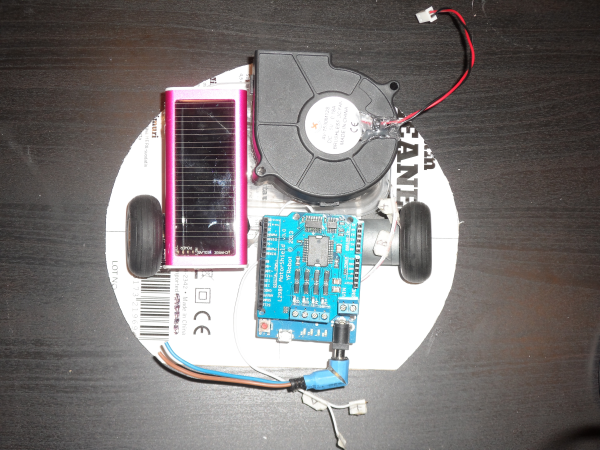
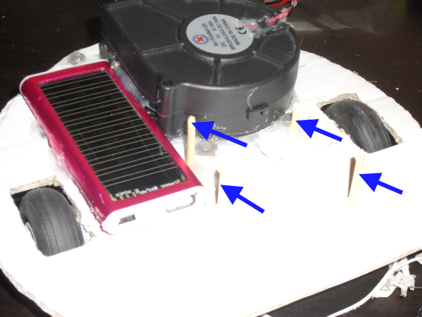
On the upper side of the chassis, the batteries or battery compartment and attachments for the Arduino module are glued. In this case, used pieces of wooden skewers glued with hot glue.
Arduino module with motor-shield installed in the mount. Battery wires from Arduino and cut to size.
The power wires are twisted (even better soldered), isolated and connected to the turbine, Arduino, motor-shield and battery.

Bumpers are cut out of the cardboard strips, folded and glued together in a semicircle:

The bumpers are glued to the sides of the chassis - the chassis is pre-cut so that the glued bumpers can be pressed down slightly against it when they collide with an obstacle:

Two conductors are attached to two pieces of tin (pre-ground for good contact) and fixed on them with hot melt:

The pieces of tin are glued to the bumpers, their wires will be connected to Arduino (to pins 5 and 8 for the given program). In front of them, the contacts of two other conductors are attached, which are connected to the GND Arduino contacts.

To filter the dust, a multi-layer fibrous synthetic fabric is used (for example, a rectangle cut out of the kitchen table wiping cloth) - the filter is placed on the bottom of the chassis and pressed against the box with magnets glued to it:

A long hole is cut into the box - with the edges curved outward. A round support is glued to the box - a piece of plastic or cork so that the curved edge of the opening of the box is 1 mm above the floor when the robot is mounted on the wheels and rests on the support. The height of the support can be used to adjust the cleaning quality and patency of the robot:

If the box has too high walls - they can be shortened by pasting magnets:

Program for Arduino and motor-shield on Github .
Motor with gearbox - 100-200 revolutions per minute (RPM). Gearboxes for motors can be printed on a 3D printer - this is what a cardboard robot looks like with printed out gearmotors. It is also desirable to solder 0.1 μF capacitors between the contacts of the motors (usually on radio-etched toys such capacitors are already soldered).
Turbine - 5 volts, 0.2 A; 12 volts, 0.2 A is better (it is more powerful), but it requires a 5 volt to 12 volt converter (Step-Up converter). Located on ebay according to “cooling blower fan 5V”.
Arduino motor-shield - in this case, YFRobot on a L298P microchip; other motor-shield may have different contact numbers and be programmed differently by software - for example, this one . It is also possible to use external engine control modules or just the L293D microcircuit (the latter will require soldering).
(many pictures)
Required components:
- Arduino module
- Motor-shield - engine control module, also known as H-Bridge
- Two motors with gears and power wires
- Two wheels
- A set of batteries, batteries or power bank for 5 volts
- Cooling turbine for a computer (not a fan, namely a turbine) for 5 volts (or 12 volts - with a voltage converter of 5 volts - 12 volts)
- Strong Magnets Set
- USB cable
- Power cable for Arduino
- Wires for connecting Arduino pins
- Thick cardboard
- Glue gun with glue
- A piece of tin (you can from a tin can or an aluminum can from under the juice)
- Plastic box - capacity for collected dust
The approximate location of the components is determined, cut out of a cardboard circle of a suitable size - the robot chassis:
')
Holes are cut in the chassis for the wheels of gearboxes mounted on the axles and under the inlet of the impeller. Motors are attached to the chassis with plastic ties:
The turbine is glued to the chassis with hot melt:
Turbine - at the top of the chassis, motors - below:
The box contour is marked on the underside of the chassis (one that collects dust) and holes are punctured around the contour, noting the location of the magnets — the box will be held onto the chassis by the magnets (the simplest of the previously tried methods):
On the upper side of the chassis magnets are glued on the ground marks-punctures. If corrugated cardboard - cut out a fragment of the upper layer by the size of the magnets:
On the underside of the chassis, magnets are applied by placing a sheet of paper under them:
A dust box is installed between the magnets and glued to them:
On the upper side of the chassis, the batteries or battery compartment and attachments for the Arduino module are glued. In this case, used pieces of wooden skewers glued with hot glue.
Arduino module with motor-shield installed in the mount. Battery wires from Arduino and cut to size.
The power wires are twisted (even better soldered), isolated and connected to the turbine, Arduino, motor-shield and battery.
Bumpers are cut out of the cardboard strips, folded and glued together in a semicircle:
The bumpers are glued to the sides of the chassis - the chassis is pre-cut so that the glued bumpers can be pressed down slightly against it when they collide with an obstacle:
Two conductors are attached to two pieces of tin (pre-ground for good contact) and fixed on them with hot melt:
The pieces of tin are glued to the bumpers, their wires will be connected to Arduino (to pins 5 and 8 for the given program). In front of them, the contacts of two other conductors are attached, which are connected to the GND Arduino contacts.
To filter the dust, a multi-layer fibrous synthetic fabric is used (for example, a rectangle cut out of the kitchen table wiping cloth) - the filter is placed on the bottom of the chassis and pressed against the box with magnets glued to it:
A long hole is cut into the box - with the edges curved outward. A round support is glued to the box - a piece of plastic or cork so that the curved edge of the opening of the box is 1 mm above the floor when the robot is mounted on the wheels and rests on the support. The height of the support can be used to adjust the cleaning quality and patency of the robot:
If the box has too high walls - they can be shortened by pasting magnets:
Program for Arduino and motor-shield on Github .
Motor with gearbox - 100-200 revolutions per minute (RPM). Gearboxes for motors can be printed on a 3D printer - this is what a cardboard robot looks like with printed out gearmotors. It is also desirable to solder 0.1 μF capacitors between the contacts of the motors (usually on radio-etched toys such capacitors are already soldered).
Turbine - 5 volts, 0.2 A; 12 volts, 0.2 A is better (it is more powerful), but it requires a 5 volt to 12 volt converter (Step-Up converter). Located on ebay according to “cooling blower fan 5V”.
Arduino motor-shield - in this case, YFRobot on a L298P microchip; other motor-shield may have different contact numbers and be programmed differently by software - for example, this one . It is also possible to use external engine control modules or just the L293D microcircuit (the latter will require soldering).
Source: https://habr.com/ru/post/375429/
All Articles