Choosing a platform for experiments with UAVs
Choose a platform to experiment with the UAV now there is nothing. There are a lot of auto pilots on the market, so a small overview of the available devices will follow first, and then consider the winner - Pixhawk (yes, yes, that’s right, no intrigue).
Criterias of choice:
Let's see what's left:

The project with the longest history (the first AVR versions of iron are dated 2003) therefore we will begin with it. In 2010, the main developer of the Pascal Brisset project died, but the community survived. To date, there are more than a dozen autopilot based on Paparazzi.
In the source codes, a lot of things have accumulated: there is a realization of integrating the Euler kinematic equations through the matrix of the cosine guide, Euler angles, quaternions; in float and integers. There is an implementation of a simple Kalman filter with 6 variables for determining orientation, and even the UKF was stuffed into the experimental branches - in general, there is something to see. All this wealth is configured for a specific device using xml files before compiling.
An incomplete list of devices based on the project is here . I will list from it a few, in my opinion, the most interesting devices:

Concept 2008 on the basis of two LPC2148, and this is interesting. The autopilot code is executed on one of the MCs, while the other provides communication with servo drives and a manual control receiver. The approach reduces the risk of losing the machine during the autopilot. The manual control channel is independent, and autopilot failure does not threaten control loss.
Modern meringue device STM32F4. It contains a full set of sensors, with the exception of GPS. The price is about $ 200.

An interesting option with a modular structure. It consists of a very tightly assembled mainboard with an STM32F4 and a complete set of sensors (including GPS and a dynamic pressure sensor) and a set of interface cards.

A set of sensors is specified when ordering. The price of the main board in the full configuration is $ 212.

On the interface boards there is nothing that could not be placed on the main (connectors, fuses). But the possibility of docking with Gumstix (so that on the OMAP3530) is very interesting:

The photo bookcase from Gumstix + NavStik + interface board. A very serious potential device is obtained in a miniature version.

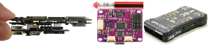
The project has two hardware platforms: CC3D and Revo.

Small-sized scarf based on the MPU-6000 sensor and the MK Cortex-M3. It has 6 outputs (PWM), 2 UART inputs, an input for connecting an RC receiver. Binding minimum, there is no protection on interfaces at all.
Between the autopilot and the iron lies its own HAL which, theoretically, can be implemented via FreeRTOS, but practically a bunch of code itself is written under STM32Fx / win / posix. The main advantage of the platform is the price of $ 30. Available, both in the official store, and on alli , and even on hk (recognition !!!).
About the official store should be said separately . When accessing from the Russian Federation, you are greeted by a blank page with a friendly phrase “You cannot access this store from your country.” Is somehow not good, especially given the fact that the team has Russian-speaking developers. The administration also behaves in a friendly manner on the forum (once they grabbed the ban for posting an advertisement for a profile job in the Russian branch, and not just blocked the user, but added ip to the blacklist, that is, a) people are not lazy; b) some kind of trigger on the RF theme is triggered).

Device based on STM32F4. On board is a pressure sensor and a modem at 433 MHz (for receiving interference directly from the controller, since the screen is not earthly). The device was developed for a long time, but finally released. The documentation has not been published, so the Chinese have no clones yet, the official sellers have the price of $ 100-130 (see the note about the native store above).
The math of the bins is implemented through EKF on 13/16 state variables. The filter is written in pure C using float. The code is optimized in some moments (matrix calculations), in others it is not (normalization of the quaternion costs 4 divisions instead of multiplying by the inverse). It is not clear why the filter settings are written directly in the code (it will not be easy to adjust for new sensors).
Due to the powerful controller (168 MHz with FPU), the device is suitable for experiments much more than the first.

For some applications, a small ARM on board is not enough (even if it is an M4). Above, we mentioned the Gumstix board on the OMAP3530 (Cortex-A8) in conjunction with NavStik. It would be strange if Gumstix did not do something similar on its own.

Gumstix AeroCore expansion board . Another popular "beagle" of BeagleBone with SOC from TI. There is also a suitable scarf for her:

Pictured BeagleBone IMU Cape
And finally, Intel with its Edison . There is no expansion card for it yet, but someone doubts what will happen?
It should be noted that these platforms hardly pass by the criterion of "openness", all hope was on I.MX6 , due to the completeness of the documentation, but its native SabreLight does not fit the form factor, and the other implementations do not have due popularity (purely my opinion). So we are waiting for the promised I.MX6 co with the built-in Cortex-M4 and a new suitable layout.
I will also take various Android-based MiniPCs to the detachment of development boards. Attractive, above all, for its price. On the example of the Mk808 for $ 40, we have:
There are more modern devices on the RK3288, but the issue of having a Linux port requires additional study.
Similar miniPC bolted through the UART to any autopilot described here extends its capabilities up to VSLAM (SLAM based on technical vision).
It becomes possible to use full-featured OS instead of the “micro OS” described here for the MK
with add-ons like ROS or even Simulink .
Finally got to Pixhawk. Many saw beautiful rollers with quadrocopters playing with a table tennis ball, performing acrobatic stunts, a bunch of amicable things standing. The main supplier of this Content is ETH Zurich (Swiss Federal Institute of Technology Zurich). Pixhawk is their development pixhawk.ethz.ch . Due to its academic character, the project has a beautiful architecture, both in hardware and software. From the hardware and let's start. Due to the openness, you can buy a clone on Alliexpress, which I did:
Completeness:
Total: $ 185 (6500r ... oh, it was time).
The first question that arises: how much is the Chinese clone "Chinese". Well, let's open and see.
The main unit of the device is a small box with multiple connectors.

Body material - translucent dark polycarbonate.

The body consists of two halves. The hull halves are fastened with the help of four self-tapping screws screwed into the stumps on the upper half of the hull. To simplify assembly / disassembly operations, the self-tapping screws were immediately replaced with a piece of black electrical tape visible in the first photo. In the lower left corner you can see a small compartment covering the pressure sensor on the board. Up to the pay wall of the compartment do not reach. According to Vooon, in a native device, a piece of foam rubber is placed in the compartment, but for some reason it is forgotten in the clone, it will be necessary to fix it yourself. Foam rubber damps pressure fluctuations and protects the sensor from light. (Thanks to Alex22 for pointing out the photosensitivity of the sensor.)

The main components are mounted on the bottom of the board.

On top are the interface connectors, microSD connector and several indicator LEDs.
There are no complaints about the quality of the installation - everything is smooth, the flux is washed off (except for the battery, it was obviously soldered by hand after the stove). By the way, there are no batteries among competitors (which means there is no real-time clock, or rather, no GPS is caught yet).
Plastic connectors have corresponding holes in the upper half of the case. Near each connector there is a signature. The mating connectors enter with some force. To disconnect it is absolutely impossible to pull the wire (come off). Should act as follows:
On the table, the operation does not cause difficulties, and in the field in -15C you can use the hack:
It makes sense to immediately stock up on spare cables in case of failure.
The included GPS module combines the SNS receiver with a battery and antenna and a magnetometer.

The need to make a magnetometer along with a GPS antenna arises because it is desirable to place it away from power conductors and magnetic materials. For an example on DJI, this is done like this:

All inputs / outputs connected to the connectors are statically protected, limiting resistors. Through the power supply circuits installed pass capacitors and protective diodes.

For clarity, here is a photo with a markup of parts of parts providing protection.

As a result: there are no complaints about Chinese production, the board can be carefully varnished and flying! And if you supplement the metal case with the removed connectors, the device will look even against the background of much more expensive commercial autopilots.
And now let us recall the competitors from the beginning of the article whose legs of the MK are directly connected to the connectors. The largest parts on the board are two MK. A large STM32F427 (168 MHz, 256KB of RAM, 2MB FLASH) and a smaller STM32F103 that performs the functions of a failsafe controller (controlling the device when the main autopilot algorithm fails). Those. We see the same architecture as in Paparazzi 2008, but on the modern element base. It can be noted here that in modern SOC there is a tendency to embed small MK (cores) to solve auxiliary tasks (as well as hard real-time tasks), but here they did it easier - they set up a separate MK. I will not describe the installed sensors / derived interfaces in detail, everything is on the project page .
The project is based on NuttX RTOS . NuttX is a small posix OS. The system has ROMFS support, which allows some of the settings to be made via configuration files when the system is running (compare with the build via configuration xml for paparazzi).
The BINS algorithms are based on EKF and are available as a separate InertialNav project. There are implementation options for different sensor sets: 21, 22, 23, and 24 state variables. The filter code is well documented and partially obtained by automatic generation from MATLAB. The project contains MATLAB source files, data archives - a complete set for experiments.
Working with the device "on the table" is extremely simple: when connected to USB, a new virtual COM port appears in the system that can be used to communicate with the autopilot (in a real device, instead of USB, there will be a UART-connected radio channel).
The project is compatible with the QgroundControl ground control station code . The interaction takes place through the open protocol MAVLink .

The control station allows you to customize the autopilot for a specific aircraft, set the flight rear and control the progress of its execution, that is, everything that the user needs.
Enough for the user, but we will go further ...
Installing the development environment and loading the project is done in two clicks, even from under windows:
Everything, we have Eclipse with the project:

Whoever had to configure Eclipse to work with ARM would appreciate the simplicity.
Now it remains to tighten the ST-LINK and you can start debugging ... but it will be in the next article that will appear only after the accumulation and awareness of the relevant experience.
Criterias of choice:
- open architecture (software & hardware);
- modern element base (disappears all the pattern * avr *);
- competent, beautiful architecture (templates * ardu * o and * Rasberi * disappear);
- SIL / HIL simulation mechanisms;
- availability of open ground station software.
Let's see what's left:
- Paparazzi Project
- Classix
- Lisa / MX V2.1
- NavStik
- OpenPilot Project
')- CC3D
- Revo
- IMU Development Boards
- Gumstix
- Beagleboard
- MiniPC
- Pixhawk Autopilot
- Hardware
- Software part
1. Paparazzi Project
The project with the longest history (the first AVR versions of iron are dated 2003) therefore we will begin with it. In 2010, the main developer of the Pascal Brisset project died, but the community survived. To date, there are more than a dozen autopilot based on Paparazzi.
In the source codes, a lot of things have accumulated: there is a realization of integrating the Euler kinematic equations through the matrix of the cosine guide, Euler angles, quaternions; in float and integers. There is an implementation of a simple Kalman filter with 6 variables for determining orientation, and even the UKF was stuffed into the experimental branches - in general, there is something to see. All this wealth is configured for a specific device using xml files before compiling.
An incomplete list of devices based on the project is here . I will list from it a few, in my opinion, the most interesting devices:
Paparazzi Classix
Concept 2008 on the basis of two LPC2148, and this is interesting. The autopilot code is executed on one of the MCs, while the other provides communication with servo drives and a manual control receiver. The approach reduces the risk of losing the machine during the autopilot. The manual control channel is independent, and autopilot failure does not threaten control loss.
Paparazzi Lisa / MX V2.1
Modern meringue device STM32F4. It contains a full set of sensors, with the exception of GPS. The price is about $ 200.
Paparazzi NavStik
An interesting option with a modular structure. It consists of a very tightly assembled mainboard with an STM32F4 and a complete set of sensors (including GPS and a dynamic pressure sensor) and a set of interface cards.
A set of sensors is specified when ordering. The price of the main board in the full configuration is $ 212.
On the interface boards there is nothing that could not be placed on the main (connectors, fuses). But the possibility of docking with Gumstix (so that on the OMAP3530) is very interesting:
The photo bookcase from Gumstix + NavStik + interface board. A very serious potential device is obtained in a miniature version.
2. OpenPilot Project
The project has two hardware platforms: CC3D and Revo.
OpenPilot CC3D (STM32F1)
Small-sized scarf based on the MPU-6000 sensor and the MK Cortex-M3. It has 6 outputs (PWM), 2 UART inputs, an input for connecting an RC receiver. Binding minimum, there is no protection on interfaces at all.
Between the autopilot and the iron lies its own HAL which, theoretically, can be implemented via FreeRTOS, but practically a bunch of code itself is written under STM32Fx / win / posix. The main advantage of the platform is the price of $ 30. Available, both in the official store, and on alli , and even on hk (recognition !!!).
About the official store should be said separately . When accessing from the Russian Federation, you are greeted by a blank page with a friendly phrase “You cannot access this store from your country.” Is somehow not good, especially given the fact that the team has Russian-speaking developers. The administration also behaves in a friendly manner on the forum (once they grabbed the ban for posting an advertisement for a profile job in the Russian branch, and not just blocked the user, but added ip to the blacklist, that is, a) people are not lazy; b) some kind of trigger on the RF theme is triggered).
OpenPilot Revo (STM32F4)
Device based on STM32F4. On board is a pressure sensor and a modem at 433 MHz (for receiving interference directly from the controller, since the screen is not earthly). The device was developed for a long time, but finally released. The documentation has not been published, so the Chinese have no clones yet, the official sellers have the price of $ 100-130 (see the note about the native store above).
The math of the bins is implemented through EKF on 13/16 state variables. The filter is written in pure C using float. The code is optimized in some moments (matrix calculations), in others it is not (normalization of the quaternion costs 4 divisions instead of multiplying by the inverse). It is not clear why the filter settings are written directly in the code (it will not be easy to adjust for new sensors).
Due to the powerful controller (168 MHz with FPU), the device is suitable for experiments much more than the first.
3.Maculet Cards with IMU
For some applications, a small ARM on board is not enough (even if it is an M4). Above, we mentioned the Gumstix board on the OMAP3530 (Cortex-A8) in conjunction with NavStik. It would be strange if Gumstix did not do something similar on its own.
Gumstix AeroCore expansion board . Another popular "beagle" of BeagleBone with SOC from TI. There is also a suitable scarf for her:
Pictured BeagleBone IMU Cape
And finally, Intel with its Edison . There is no expansion card for it yet, but someone doubts what will happen?
It should be noted that these platforms hardly pass by the criterion of "openness", all hope was on I.MX6 , due to the completeness of the documentation, but its native SabreLight does not fit the form factor, and the other implementations do not have due popularity (purely my opinion). So we are waiting for the promised I.MX6 co with the built-in Cortex-M4 and a new suitable layout.
I will also take various Android-based MiniPCs to the detachment of development boards. Attractive, above all, for its price. On the example of the Mk808 for $ 40, we have:
- RK3066 2 x Cortex-A9 1.6GHz;
- 1GB of RAM;
- 8GB Flash;
- WiFi;
- SD connector;
- UART on the board;
There are more modern devices on the RK3288, but the issue of having a Linux port requires additional study.
Similar miniPC bolted through the UART to any autopilot described here extends its capabilities up to VSLAM (SLAM based on technical vision).
It becomes possible to use full-featured OS instead of the “micro OS” described here for the MK
with add-ons like ROS or even Simulink .
4.Pixhawk Autopilot
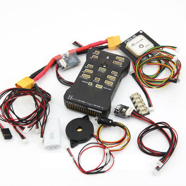
Finally got to Pixhawk. Many saw beautiful rollers with quadrocopters playing with a table tennis ball, performing acrobatic stunts, a bunch of amicable things standing. The main supplier of this Content is ETH Zurich (Swiss Federal Institute of Technology Zurich). Pixhawk is their development pixhawk.ethz.ch . Due to its academic character, the project has a beautiful architecture, both in hardware and software. From the hardware and let's start. Due to the openness, you can buy a clone on Alliexpress, which I did:
Completeness:
- autopilot itself;
- GPS module with antenna, battery and magnetometer;
- button with integrated LED;
- DC / DC converter with current sensor;
- USB-> UART / I2C adapter;
- I2C splitter.
Total: $ 185 (6500r ... oh, it was time).
The first question that arises: how much is the Chinese clone "Chinese". Well, let's open and see.
Hardware
The main unit of the device is a small box with multiple connectors.
Body material - translucent dark polycarbonate.
The body consists of two halves. The hull halves are fastened with the help of four self-tapping screws screwed into the stumps on the upper half of the hull. To simplify assembly / disassembly operations, the self-tapping screws were immediately replaced with a piece of black electrical tape visible in the first photo. In the lower left corner you can see a small compartment covering the pressure sensor on the board. Up to the pay wall of the compartment do not reach. According to Vooon, in a native device, a piece of foam rubber is placed in the compartment, but for some reason it is forgotten in the clone, it will be necessary to fix it yourself. Foam rubber damps pressure fluctuations and protects the sensor from light. (Thanks to Alex22 for pointing out the photosensitivity of the sensor.)
The main components are mounted on the bottom of the board.
On top are the interface connectors, microSD connector and several indicator LEDs.
There are no complaints about the quality of the installation - everything is smooth, the flux is washed off (except for the battery, it was obviously soldered by hand after the stove). By the way, there are no batteries among competitors (which means there is no real-time clock, or rather, no GPS is caught yet).
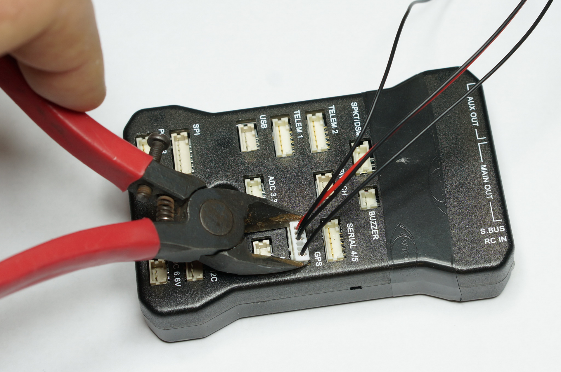
Plastic connectors have corresponding holes in the upper half of the case. Near each connector there is a signature. The mating connectors enter with some force. To disconnect it is absolutely impossible to pull the wire (come off). Should act as follows:
On the table, the operation does not cause difficulties, and in the field in -15C you can use the hack:
It makes sense to immediately stock up on spare cables in case of failure.
The included GPS module combines the SNS receiver with a battery and antenna and a magnetometer.
The need to make a magnetometer along with a GPS antenna arises because it is desirable to place it away from power conductors and magnetic materials. For an example on DJI, this is done like this:
All inputs / outputs connected to the connectors are statically protected, limiting resistors. Through the power supply circuits installed pass capacitors and protective diodes.
For clarity, here is a photo with a markup of parts of parts providing protection.
As a result: there are no complaints about Chinese production, the board can be carefully varnished and flying! And if you supplement the metal case with the removed connectors, the device will look even against the background of much more expensive commercial autopilots.
And now let us recall the competitors from the beginning of the article whose legs of the MK are directly connected to the connectors. The largest parts on the board are two MK. A large STM32F427 (168 MHz, 256KB of RAM, 2MB FLASH) and a smaller STM32F103 that performs the functions of a failsafe controller (controlling the device when the main autopilot algorithm fails). Those. We see the same architecture as in Paparazzi 2008, but on the modern element base. It can be noted here that in modern SOC there is a tendency to embed small MK (cores) to solve auxiliary tasks (as well as hard real-time tasks), but here they did it easier - they set up a separate MK. I will not describe the installed sensors / derived interfaces in detail, everything is on the project page .
Software part
The project is based on NuttX RTOS . NuttX is a small posix OS. The system has ROMFS support, which allows some of the settings to be made via configuration files when the system is running (compare with the build via configuration xml for paparazzi).
The BINS algorithms are based on EKF and are available as a separate InertialNav project. There are implementation options for different sensor sets: 21, 22, 23, and 24 state variables. The filter code is well documented and partially obtained by automatic generation from MATLAB. The project contains MATLAB source files, data archives - a complete set for experiments.
Working with the device "on the table" is extremely simple: when connected to USB, a new virtual COM port appears in the system that can be used to communicate with the autopilot (in a real device, instead of USB, there will be a UART-connected radio channel).
The project is compatible with the QgroundControl ground control station code . The interaction takes place through the open protocol MAVLink .
The control station allows you to customize the autopilot for a specific aircraft, set the flight rear and control the progress of its execution, that is, everything that the user needs.
Enough for the user, but we will go further ...
Installing the development environment and loading the project is done in two clicks, even from under windows:
- swing toolchain
- Run PX4_Software_download.bat - the project is being downloaded;
- import the project into Eclipse.
Everything, we have Eclipse with the project:
Whoever had to configure Eclipse to work with ARM would appreciate the simplicity.
Now it remains to tighten the ST-LINK and you can start debugging ... but it will be in the next article that will appear only after the accumulation and awareness of the relevant experience.
References:
- www.pixhawk.org - an open platform project for UAVs;
- www.paparazziuav.org - project of an open platform for UAVs;
- www.openpilot.org - project of an open platform for UAVs;
- www.qgroundcontrol.org - open source ground control station software;
- www.gumstix.com - manufacturer of miniature SBC;
- www.beagleboard.org/bone - TI 's Cheap SOC-Based SBC.
Addition. Links to commercial autopilots for UAVs:
- NAZA-M-V2 autopilot from DJI;
- Micropilot is one of the first commercial manufacturers;
- UAVOS - Belarusian / Swiss platform;
- SWIFT AI - the domestic autopilot platform with an emphasis on FPV;
- AEROB - a domestic platform from Skolkovo partner;
- AVAKS-GeoService AP-05 - a domestic platform with
blackjackQNX, redundancy and RS-485; - RUAV STA3x - domestic platform with Simulink similar to the visual editor. "The boxed product" with the documentation.
Source: https://habr.com/ru/post/375239/
All Articles