Solution FizzBuzz on FPGA with video generation
This article describes how to generate a video signal on an FPGA using FizzBuzz as an example. Generating a video turned out to be easier than I expected - easier than the previous task with the consistent output of FizzBuzz to FPGA . I got a little carried away with the project, so I added animation, multi-colored text and giant jumping words on the screen.
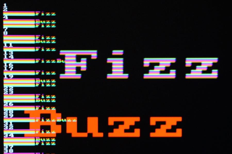
FizzBuzz on the FPGA board. The board generates a direct VGA video signal with the animation of the words “Fizz” and “Buzz”
If you are not familiar with the FizzBuzz task , then it is to write a program that prints the numbers from 1 to 100, where the three-fold units are replaced by the word Fizz, the five-fold numbers are replaced by the word Buzz, and the multiple fifteen numbers are replaced by the FizzBuzz word. Since FizzBuzz is implemented in several lines of code, this task is given at interviews in order to weed out those who do not know how to program. But on the FPGA solution is much more difficult.
FPGA ( user-programmable gate array ) is an interesting chip. It is programmed to execute arbitrary digital logic. It is possible to construct a complex circuit without laying the physical channels between the individual valves and the flip-flops. The microcircuit can turn into anything from a logic analyzer to a microprocessor and a video generator. For this project I used the Mojo FPGA board (in the photo).
')
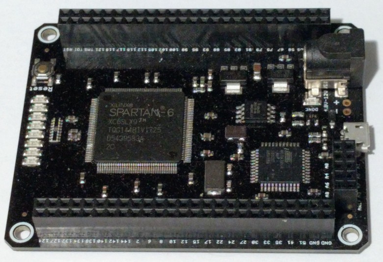
Mojo FPGA board. The big chip on the board is the Spartan 6 FPGA
For FPGA, there is a definite learning curve, because here you are developing circuits, rather than writing software that runs on a processor. But if you can use the FPGA to blink five LEDs, then you are generally ready to realize the output of a VGA video signal. The VGA video format is much simpler than I expected: only three signals for pixels (red, green and blue) and two signals for horizontal and vertical synchronization.
The basic idea is to use two counters: one for pixels horizontally and one for vertical lines. At each point on the screen, these coordinates generate the desired pixel color. In addition, horizontal and vertical synchronization pulses are generated when the counters are in the corresponding position. I used the basic resolution of VGA 640 × 480 2 where you need to count to 800 and 525 1 eleven . Horizontally in each line 800 pixels: 640 visible, 16 empty, 96 for horizontal synchronization and another 48 empty pixels. (Such strange parameters are used for historical reasons). Meanwhile, the vertical counter should count 525 lines: 480 lines of the image, 10 empty, 2 lines of vertical synchronization and 33 more empty.
Putting it all together, I developed a
Although Verilog is similar to a normal programming language, it works quite differently. This code does not generate instructions that are sequentially executed by the processor, but creates a circuit in the FPGA chip. It creates registers from the triggers for
Returning to the
The “useful” part of the VGA signal is the red, green and blue pixel signals that control what appears on the screen. To check the scheme, I wrote a few lines to activate
I ran the code on the FPGA board - and nothing happened. The monitor remained black. What went wrong? Fortunately, after a couple of seconds 4 the monitor has completed its normal startup cycle and displayed the issue. I was pleasantly surprised that the issue of VGA worked the first time, even if it is an arbitrary color blocks. five
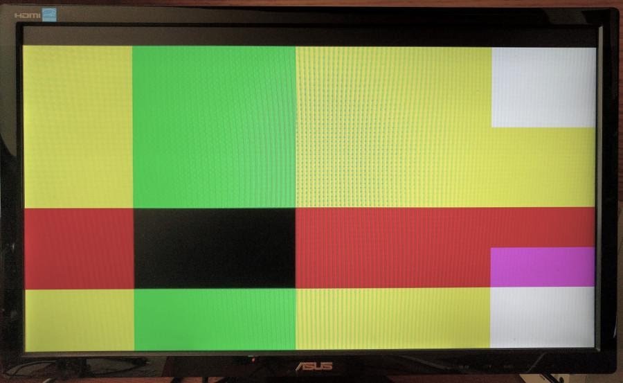
My first VGA program generates arbitrary color blocks on the screen. Not very meaningful, but everything works fine
The next step is to display text characters on the screen. I implemented a pixel generation module for 8 × 8 characters. Instead of supporting the full set of ASCII characters, here are only the characters needed for FizzBuzz: from 0 to 9, “B”, “F”, “i”, “u”, “z” and a space. Conveniently, the whole set fit in 16 characters, that is, in a four-bit value.
Thus, the module receives a four-bit character code and a three-bit line number (for eight lines per character) - and outputs eight pixels for a given character string. All code (below is a fragment, and the full code is here ) is just a big
I updated the top-level program to use the lower bits of the
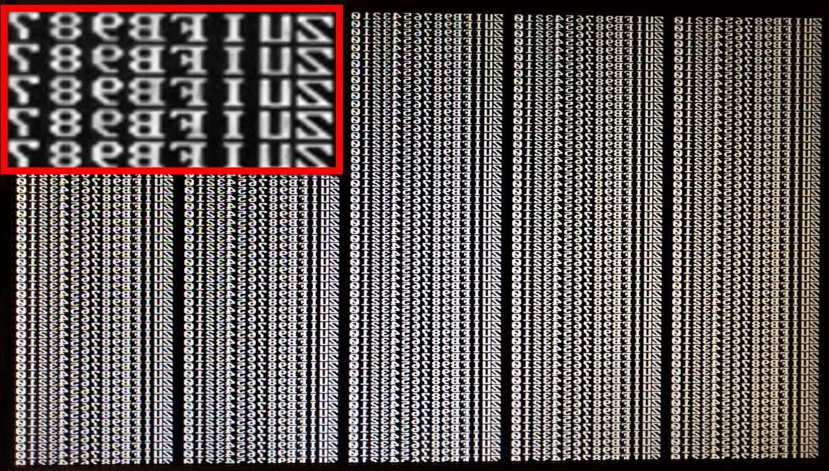
My first text implementation (enlarged area in red outline). Because of the error, all the characters go backwards
Hell, in my character generator, bit 7 is on the left, and in the values of the pixel index it is on the right, so the characters are displayed backwards. But it is easy to fix.
Having adjusted the display of characters, you need to get the correct characters for the output of FizzBuzz. The algorithm is the same as in the previous program , so here I will give only the main points.
Converting numbers from 1 to 100 into characters is trivial to implement on a microprocessor, but more difficult in digital logic, because there is no built-in division operation. The division into 10 and 100 requires a lot of logical elements. I decided to use a binary decimal counter (BCD) with separate four-bit counters for each of the bits.
The next task is to check the multiplicity of 3 and 5. Like simple division, division with the remainder is easy to implement on a microprocessor, but difficult in digital logic. Instead of calculating the values, I made counters for the residuals from division by 3 and 5. For example, division with the remainder by three simply counts 0, 1, 2, 0, 1, 2 ... (for other options, see notes 7 ).
The FizzBuzz issue string contains up to eight characters. The “fizzbuzz” module ( source code ) outputs the corresponding eight four-bit characters as a 32-bit
The FizzBuzz module needs a signal to increase the counter to the next number, so I changed the
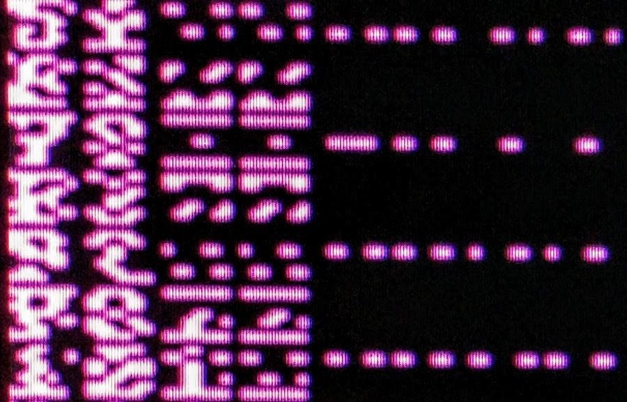
Changing a character in each line gives out mysterious hieroglyphs, but not the desired result.
The error is that I moved to the next value of FizzBuzz after each row of pixels instead of waiting for 8 lines of drawing the entire character. Thus, each displayed symbol consisted of slices of eight different symbols. Increasing the FizzBuzz counter every 8 lines corrects the problem, as shown below. (Debugging VGA code is much easier than other tasks on FPGAs, because the problems are immediately visible on the screen. No need to mess around with the oscilloscope trying to figure out what went wrong).
Giving FizzBuzz on a VGA monitor
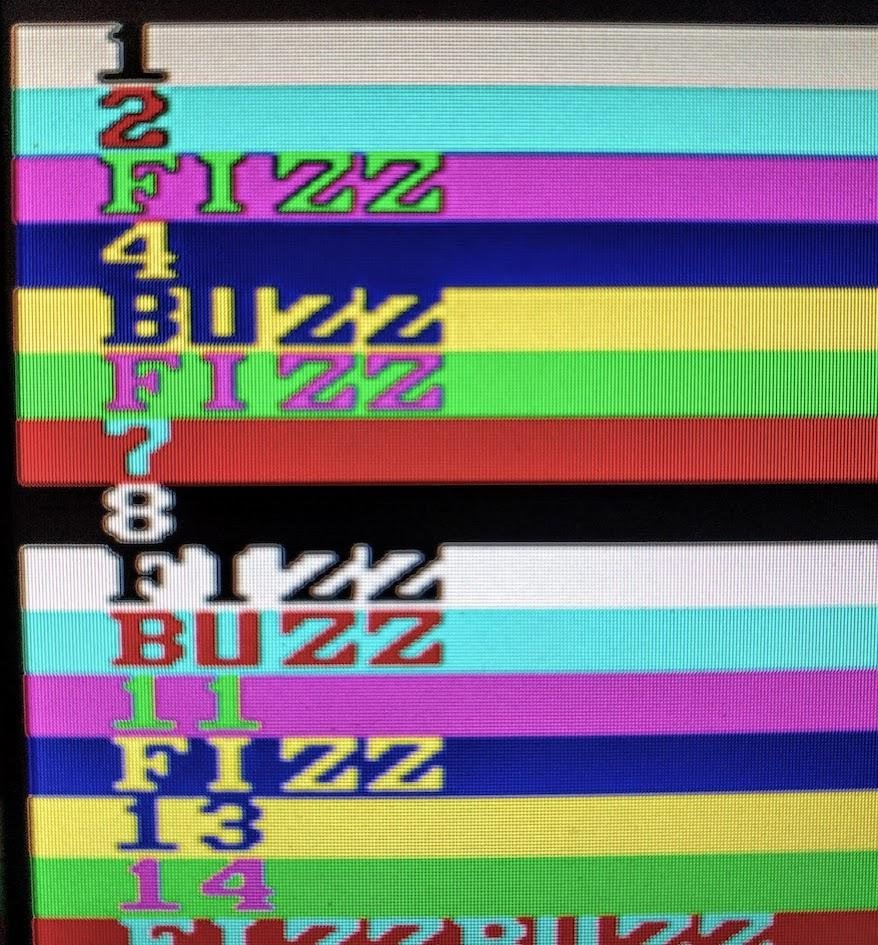
Now FizzBuzz has appeared on the monitor, but the static display is boring. Changing the foreground and background colors for each row is made simple — use some bits of the
If the foreground and background color depends on the line, the text looks more interesting.
Then I added a primitive animation. The first step is to add the output of the
Trying different graphic effects is fun and exciting, because the result is immediately visible. I launched “Fizz” and “Buzz” with a rainbow trace on the screen (in the spirit of Nyan Cat ). For this, I changed the initial positions of the characters in accordance with the counter. For the rainbow effect on the characters, colors are selected by line numbers (therefore, each character string can be a different color) and a rainbow trail is added.
End result close up
Finally, I added another effect - giant words “Fizz” and “Buzz”, bouncing off the edges of the screen. The effect is based on rebounding an invisible contour (like an FPGA Pong ), inside of which is the word 8 . The variable
In this project, I used a simple Mojo V3 FPGA development board for beginners. It has the FPGA of the Xilinx Spartan 6 family. Although it is one of the smallest FPGAs, it has 9000 logic cells and 11,000 triggers - so the kid is capable of a lot. (For other options, see the list of cheap FPGA cards ).
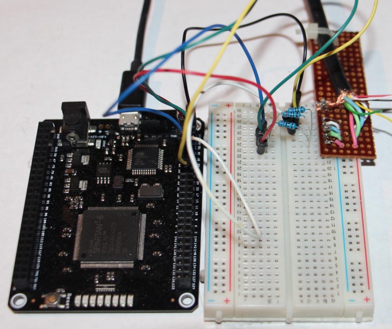
Connecting an FPGA board to a VGA is almost trivial: there are only three 270Ω resistors. The development board simply attaches the cable to the terminal block.
If you want to use VGA, it's easier to take a development board with a VGA connector. But if you don’t have one (like Mojo, for example), connecting VGA anyway won't be a problem. Simply place the 270Ω resistors between the red, green, and blue FPGA output pins and the VGA connection. Horizontal and vertical sync signals can be received directly from the FPGA. 9
I used the Xilinx development environment (called ISE) to write and synthesize Verilog code. For details on writing code and downloading it to the FPGA card, see my previous article . To indicate specific physical contacts of the FPGA, I added a few lines to the
Output from FPGA to VGA is a common phenomenon, so you can find on the Web a number of projects such as FPGA Pong , 24-bit color from the DAC chip , Basys 3 board and image output . If schema is needed, see this page . In the book "FPGA Programming," an entire chapter is devoted to this topic.
The VGA format may seem a bit strange, but if you look at the history of television and CRT ( cathode ray tube ), then everything becomes clear. In a CRT, a beam of electrons passes through the screen, highlighting the phosphor coating to display the picture. Scanning takes place in a raster array: the beam scans the screen from left to right, and then the horizontal sync pulse causes it to quickly move to the left for a horizontal reversing sweep . The process is repeated line by line until the vertical synchronization pulse at the bottom of the screen starts the vertical reverse sweep and the beam returns up. With horizontal and vertical sweep, the beam is dimmed, so the reverse does not draw lines on the screen. The diagram below shows a raster scan pattern.
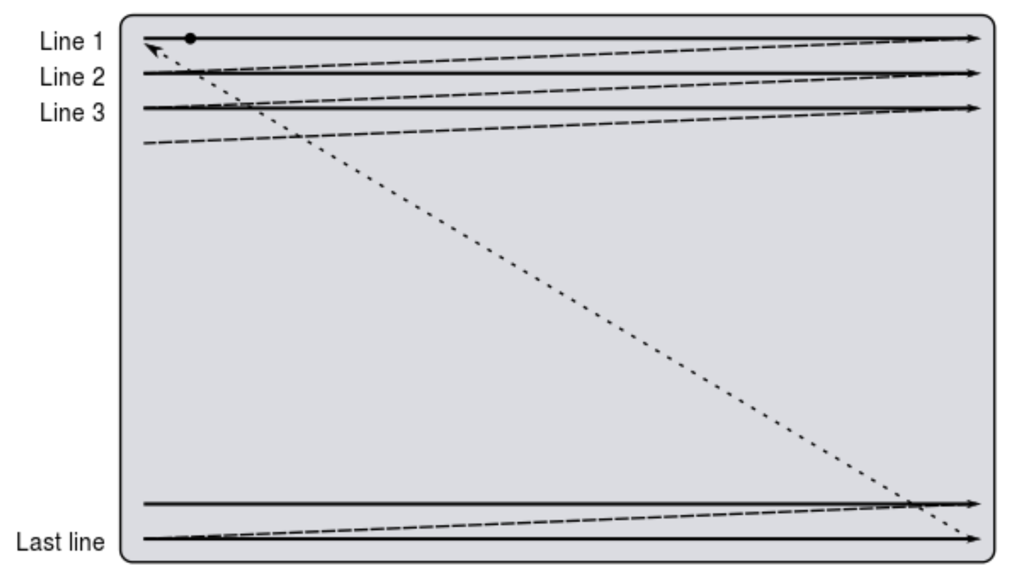
CRT Raster Template ( Wikipedia )
These characteristics are stored in VGA, including horizontal and vertical sync pulses, as well as long video muting intervals.
In 1953, the NTSC color television standard appeared. ten However, VGA is much simpler than NTSC, as it uses five wires for synchronization and color signals, and does not wedge everything into one signal with complex coding. One of the strange features of NTSC, which is transferred to VGA, is that the refresh rate of the screen is not the declared 60 hertz, but in reality is 59.94 Hz. eleven
The trace of the oscilloscope below shows the VGA signal for two lines. Horizontal synchronization pulses (yellow) indicate the beginning of each line. The short red, green and blue pulses at the beginning of the line are the white pixels from the FizzBuzz number. The red signal in the middle of the line is the floating red word “Buzz”.
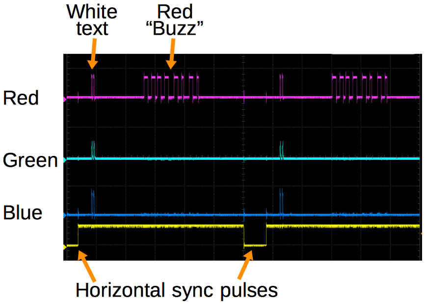
The trace of the oscilloscope signals VGA shows red, green and blue signals, as well as horizontal synchronization
The conclusion from FPGA to VGA turned out to be much easier than I expected, but they definitely won't take me to work if they ask the FizzBuzz task at an FPGA interview! If you are interested in FPGA, I highly recommend playing with the video output. This is not much more complicated than flashing LED, but much more useful. Video signal generation is also much more interesting than debugging on an oscilloscope - you can immediately see the result on the screen. And even if something goes wrong, still the result is often fun.
1. The VGA signal should have a clock speed for pixels of 25.175 MHz. Instead, I divided the 50 MHz Mojo clock rate into two to get 25 MHz. The VGA standard says that a clock frequency of 25.175 MHz ± 0.5% is allowed. The frequency of 25 MHz differs by 0.7%, so it is technically a little inconsistent with the specification. But the monitors are designed to process the signal from cheap video cards, so they usually show everything that is sent to them. [return]
2. Detailed timings for dozens of standard video resolutions, see here . On page 17, the resolution is 640 × 480 60 Hz, which I used. [return]
3. When I forgot to clear the pixels outside the permissible area of the screen, the monitor still showed an image, but very dim, because the monitor was confused what voltage our “dark” one corresponds to. This is just in case you find that your display is suddenly darkened for no apparent reason. [return]
4. It’s just amazing what an LCD display has to do to display a VGA image for a CRT. The display should examine the incoming signal and “guess” at what resolution the video from the computer goes. Then you need to re-sample the video signal in accordance with the resolution of the LCD panel. Finally, new pixel data is sent to the LCD. [return]
5. For some reason, the output is shifted down by about 25 pixels. It was perfectly displayed on another monitor, so I am not sure whether something is aligned with my monitor, or I have an error. This could be adjusted by delaying the vertical sync pulse by 25 lines. [return]
6. It would be tedious to enter all the code to generate characters, so I wrote a Python program to generate Verilog code from a font file. The original font is here . [return]
7. After my last FPGA article on FizzBuzz, readers suggested some other approaches, so I tried them in the VGA project. With counters from the remainder of the division (my initial approach), the whole project takes 276 LUT (lookup tables) and 277 triggers. One reader suggested using ring counters (that is, with one bit shifted) instead of binary counters for the remainder of the division. This requires 277 lookup tables and 281 triggers, so a little worse. Another suggestion was to add the digits and take the remainder of the division by 3. Here the logic increases the number of lookup tables to 305, which is much worse. Adding residues from division (instead of digits) reduces the number of lookup tables to 289, which is still worse than the original method. [return]
8. Large floating words, in fact, are sprites - raster images that can be arbitrarily arranged on the screen. Sprites were popular in video games and on computers of the 70s and early 80s, when Pacman, Atari and Commodore 64 appeared. Sprites allow you to animate on slow processors. Instead of moving all the pixels in memory, the processor simply updates the coordinates of the sprite. The top level code ( source code ) ties together the pieces and combines everything on the screen: text, rainbow trail, the giant word “Fizz” (in the rainbow pattern) and the giant “Buzz” (red). [return]
9. To connect the VGA monitor, I cut the VGA cable in half and connected its wires to the FPGA board, using the cable from the old project to read the data from the monitor using I2C . It is better not to use this approach: tiny wiring is difficult to solder and they break easily. Better use a regular VGA connector. The interface is simply three 270Ω resistors that receive the correct voltage for a red, green, and blue signal.You can use more resistors for additional colors. So you essentially construct two-bit (or more) converters DAC. [return]
10. NTSC standard is very smart to introduce color support, while remaining compatible with black and white TVs. However, it is very difficult to understand. I was frightened by the talk of color coding in a phase and quadrature with color subcarriers and a color burst signal. Here, encoding is much more complicated than that of VGA, because NTSC combines color and timing in one transmission channel. [return]
11. Although the update rate for the monitors is 60 Hz, the actual value is 59.94 Hz. This strange frequency goes back to the origins of color television. The refresh rate of the screen of 60 Hz was chosen to level the interference from the power line. But in order to prevent carrier frequency interference for color and sound frequency, it was necessary to adjust the frequencies, as a result of which the screen refresh rate was set to 59.94 Hertz. This is almost like numerology, but the choice of frequency is explained in detail in this video and on Wikipedia . [return]
FizzBuzz on the FPGA board. The board generates a direct VGA video signal with the animation of the words “Fizz” and “Buzz”
If you are not familiar with the FizzBuzz task , then it is to write a program that prints the numbers from 1 to 100, where the three-fold units are replaced by the word Fizz, the five-fold numbers are replaced by the word Buzz, and the multiple fifteen numbers are replaced by the FizzBuzz word. Since FizzBuzz is implemented in several lines of code, this task is given at interviews in order to weed out those who do not know how to program. But on the FPGA solution is much more difficult.
FPGA ( user-programmable gate array ) is an interesting chip. It is programmed to execute arbitrary digital logic. It is possible to construct a complex circuit without laying the physical channels between the individual valves and the flip-flops. The microcircuit can turn into anything from a logic analyzer to a microprocessor and a video generator. For this project I used the Mojo FPGA board (in the photo).
')
Mojo FPGA board. The big chip on the board is the Spartan 6 FPGA
VGA signal generation
For FPGA, there is a definite learning curve, because here you are developing circuits, rather than writing software that runs on a processor. But if you can use the FPGA to blink five LEDs, then you are generally ready to realize the output of a VGA video signal. The VGA video format is much simpler than I expected: only three signals for pixels (red, green and blue) and two signals for horizontal and vertical synchronization.
The basic idea is to use two counters: one for pixels horizontally and one for vertical lines. At each point on the screen, these coordinates generate the desired pixel color. In addition, horizontal and vertical synchronization pulses are generated when the counters are in the corresponding position. I used the basic resolution of VGA 640 × 480 2 where you need to count to 800 and 525 1 eleven . Horizontally in each line 800 pixels: 640 visible, 16 empty, 96 for horizontal synchronization and another 48 empty pixels. (Such strange parameters are used for historical reasons). Meanwhile, the vertical counter should count 525 lines: 480 lines of the image, 10 empty, 2 lines of vertical synchronization and 33 more empty.
Putting it all together, I developed a
vga module ( source code ) for generating VGA signals. The code is written in Verilog, this is the standard language for FPGA. I will not explain in detail Verilog: I hope it is enough to show how it works. In the code below, the counters x and y implemented. The first line indicates that the action was taken at the positive edge of each (50 MHz) clock signal. The next line switches clk25 on each clock, generating a 25 MHz signal. (The only confusion is that <= indicates an assignment, not a comparison). This code increases the x counter from 0 to 799. At the end of each line, y increases from 0 to 524. Thus, the code generates the necessary pixel and row counters. always @(posedge clk) begin clk25 <= ~clk25; if (clk25 == 1) begin if (x < 799) begin x <= x + 1; end else begin x <= 0; if (y < 524) begin y <= y + 1; end else begin y <= 0; end end end end Although Verilog is similar to a normal programming language, it works quite differently. This code does not generate instructions that are sequentially executed by the processor, but creates a circuit in the FPGA chip. It creates registers from the triggers for
clk25 , x and y . To increase x and y binary adders are generated. if turned into logic gates of register comparators. The whole circuit operates in parallel, responding to 50 MHz clock pulses. To understand FPGA, you need to step out of consistent programming thinking and think about basic patterns.Returning to the
vga module, the code below generates horizontal and vertical synchronization signals using the x and y counters. In addition, the valid flag indicates an area of 640 × 480 where the video signal should be generated; outside this area the screen should be blank. As before, these statements generate logic elements to check conditions, rather than generate code. assign hsync = x < (640 + 16) || x >= (640 + 16 + 96); assign vsync = y < (480 + 10) || y >= (480 + 10 + 2); assign valid = (x < 640) && (y < 480); The “useful” part of the VGA signal is the red, green and blue pixel signals that control what appears on the screen. To check the scheme, I wrote a few lines to activate
r , g and b in different areas of the screen, drowning everything outside of the visible ('valid') area 3 (the question mark is a ternary conditional operator, as in Java). if (valid) begin rval = (x < 120 || x > 320) ? 1 : 0; gval = (y < 240 || y > 360) ? 1 : 0; bval = (x > 500 && (y < 120 || y > 300)) ? 1 : 0; end else begin rval = 0; gval = 0; bval = 0; end I ran the code on the FPGA board - and nothing happened. The monitor remained black. What went wrong? Fortunately, after a couple of seconds 4 the monitor has completed its normal startup cycle and displayed the issue. I was pleasantly surprised that the issue of VGA worked the first time, even if it is an arbitrary color blocks. five
My first VGA program generates arbitrary color blocks on the screen. Not very meaningful, but everything works fine
Display characters on screen
The next step is to display text characters on the screen. I implemented a pixel generation module for 8 × 8 characters. Instead of supporting the full set of ASCII characters, here are only the characters needed for FizzBuzz: from 0 to 9, “B”, “F”, “i”, “u”, “z” and a space. Conveniently, the whole set fit in 16 characters, that is, in a four-bit value.
Thus, the module receives a four-bit character code and a three-bit line number (for eight lines per character) - and outputs eight pixels for a given character string. All code (below is a fragment, and the full code is here ) is just a big
case for outputting the corresponding bits. 6 In essence, this code is compiled into ROM, which is implemented in FPGA lookup tables. case ({char, rownum}) 7'b0000000: pixels = 8'b01111100; // XXXXX 7'b0000001: pixels = 8'b11000110; // XX XX 7'b0000010: pixels = 8'b11001110; // XX XXX 7'b0000011: pixels = 8'b11011110; // XX XXXX 7'b0000100: pixels = 8'b11110110; // XXXX XX 7'b0000101: pixels = 8'b11100110; // XXX XX 7'b0000110: pixels = 8'b01111100; // XXXXX 7'b0000111: pixels = 8'b00000000; // 7'b0001000: pixels = 8'b00110000; // XX 7'b0001001: pixels = 8'b01110000; // XXX 7'b0001010: pixels = 8'b00110000; // XX 7'b0001011: pixels = 8'b00110000; // XX 7'b0001100: pixels = 8'b00110000; // XX 7'b0001101: pixels = 8'b00110000; // XX 7'b0001110: pixels = 8'b11111100; // XXXXXX ... I updated the top-level program to use the lower bits of the
x coordinate for the character and pixel index, as well as the lower bits of the y coordinate for the row index. The results are shown below. The text in the red box is magnified so that you can see the characters.My first text implementation (enlarged area in red outline). Because of the error, all the characters go backwards
Hell, in my character generator, bit 7 is on the left, and in the values of the pixel index it is on the right, so the characters are displayed backwards. But it is easy to fix.
FizzBuzz string generation
Having adjusted the display of characters, you need to get the correct characters for the output of FizzBuzz. The algorithm is the same as in the previous program , so here I will give only the main points.
Converting numbers from 1 to 100 into characters is trivial to implement on a microprocessor, but more difficult in digital logic, because there is no built-in division operation. The division into 10 and 100 requires a lot of logical elements. I decided to use a binary decimal counter (BCD) with separate four-bit counters for each of the bits.
The next task is to check the multiplicity of 3 and 5. Like simple division, division with the remainder is easy to implement on a microprocessor, but difficult in digital logic. Instead of calculating the values, I made counters for the residuals from division by 3 and 5. For example, division with the remainder by three simply counts 0, 1, 2, 0, 1, 2 ... (for other options, see notes 7 ).
The FizzBuzz issue string contains up to eight characters. The “fizzbuzz” module ( source code ) outputs the corresponding eight four-bit characters as a 32-bit
line variable. (The normal way to generate video is to store all the characters or pixels of the screen in the video memory, but I decided to generate everything dynamically). The if statement (the snippet below) updates the line bits, returning “Fizz“, “Buzz“, “FizzBuzz“ or a number, depending on the circumstances. if (mod3 == 0 && mod5 != 0) begin // Fizz line[3:0] <= CHAR_F; line[7:4] <= CHAR_I; line[11:8] <= CHAR_Z; line[15:12] <= CHAR_Z; end else if (mod3 != 0 && mod5 == 0) begin // Buzz line[3:0] <= CHAR_B; line[7:4] <= CHAR_U; line[11:8] <= CHAR_Z; line[15:12] <= CHAR_Z; ... The FizzBuzz module needs a signal to increase the counter to the next number, so I changed the
vga module to indicate the start of a new line - and used it as a trigger for the transition to the next number. But testing the code showed a very strange rendition with alien characters. Below is a fragment.Changing a character in each line gives out mysterious hieroglyphs, but not the desired result.
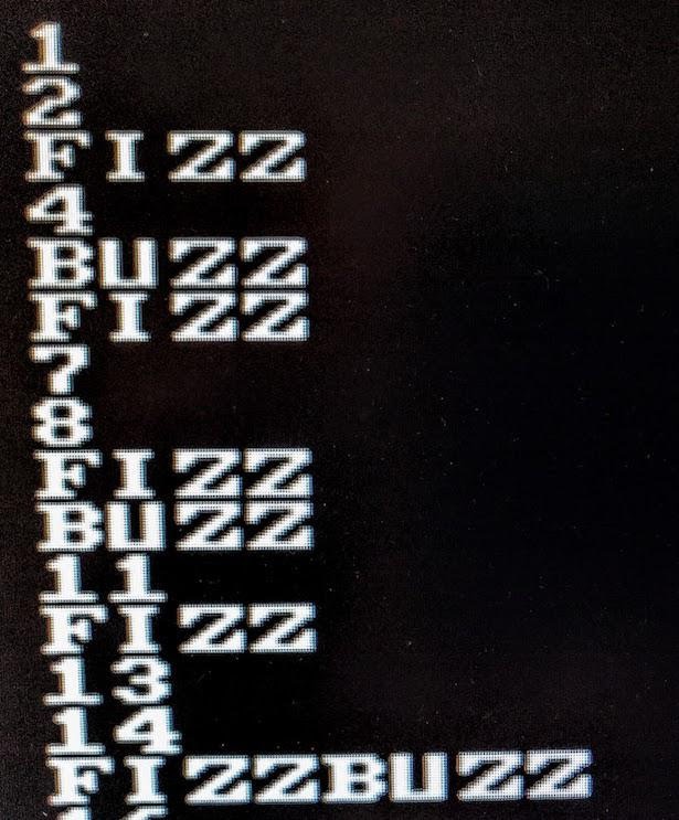
The error is that I moved to the next value of FizzBuzz after each row of pixels instead of waiting for 8 lines of drawing the entire character. Thus, each displayed symbol consisted of slices of eight different symbols. Increasing the FizzBuzz counter every 8 lines corrects the problem, as shown below. (Debugging VGA code is much easier than other tasks on FPGAs, because the problems are immediately visible on the screen. No need to mess around with the oscilloscope trying to figure out what went wrong).
Giving FizzBuzz on a VGA monitor
Now FizzBuzz has appeared on the monitor, but the static display is boring. Changing the foreground and background colors for each row is made simple — use some bits of the
y value for red, green, and blue. So we get the color text in the style of the 80s.If the foreground and background color depends on the line, the text looks more interesting.
Then I added a primitive animation. The first step is to add the output of the
vga module to indicate screen redrawing, this is a new field for every 1/60 second. I used this to dynamically change colors. (Tip: do not change color 60 times per second if you do not want to cause a headache; use a counter).Trying different graphic effects is fun and exciting, because the result is immediately visible. I launched “Fizz” and “Buzz” with a rainbow trace on the screen (in the spirit of Nyan Cat ). For this, I changed the initial positions of the characters in accordance with the counter. For the rainbow effect on the characters, colors are selected by line numbers (therefore, each character string can be a different color) and a rainbow trail is added.
End result close up
Finally, I added another effect - giant words “Fizz” and “Buzz”, bouncing off the edges of the screen. The effect is based on rebounding an invisible contour (like an FPGA Pong ), inside of which is the word 8 . The variable
dx tracks the direction of X, and dy tracks the direction of Y. On each new screen (that is, 60 times per second), the X and Y coordinates of the contour increase or decrease based on the variable direction. If the contour reaches the right or left edge, dx switches. Similarly, dy switches if the contour has reached the top or bottom edge. Then, large text is drawn within the outline using another instance of the symbol generator described earlier. The word is increased 8 times, discarding the three lower bits from the coordinate. You are probably tired of the Verilog code, so I will not show the code here, but it is published on GitHub . The final result is in the video.Hardware implementation details
In this project, I used a simple Mojo V3 FPGA development board for beginners. It has the FPGA of the Xilinx Spartan 6 family. Although it is one of the smallest FPGAs, it has 9000 logic cells and 11,000 triggers - so the kid is capable of a lot. (For other options, see the list of cheap FPGA cards ).
Connecting an FPGA board to a VGA is almost trivial: there are only three 270Ω resistors. The development board simply attaches the cable to the terminal block.
If you want to use VGA, it's easier to take a development board with a VGA connector. But if you don’t have one (like Mojo, for example), connecting VGA anyway won't be a problem. Simply place the 270Ω resistors between the red, green, and blue FPGA output pins and the VGA connection. Horizontal and vertical sync signals can be received directly from the FPGA. 9
I used the Xilinx development environment (called ISE) to write and synthesize Verilog code. For details on writing code and downloading it to the FPGA card, see my previous article . To indicate specific physical contacts of the FPGA, I added a few lines to the
mojo.ucf configuration file. Here, the pin_r red pin corresponds to pin 50 and so on. NET "pin_r" LOC = P50 | IOSTANDARD = LVTTL; NET "pin_g" LOC = P40 | IOSTANDARD = LVTTL; NET "pin_b" LOC = P34 | IOSTANDARD = LVTTL; NET "pin_hsync" LOC = P32 | IOSTANDARD = LVTTL; NET "pin_vsync" LOC = P29 | IOSTANDARD = LVTTL; Output from FPGA to VGA is a common phenomenon, so you can find on the Web a number of projects such as FPGA Pong , 24-bit color from the DAC chip , Basys 3 board and image output . If schema is needed, see this page . In the book "FPGA Programming," an entire chapter is devoted to this topic.
Understanding VGA Format
The VGA format may seem a bit strange, but if you look at the history of television and CRT ( cathode ray tube ), then everything becomes clear. In a CRT, a beam of electrons passes through the screen, highlighting the phosphor coating to display the picture. Scanning takes place in a raster array: the beam scans the screen from left to right, and then the horizontal sync pulse causes it to quickly move to the left for a horizontal reversing sweep . The process is repeated line by line until the vertical synchronization pulse at the bottom of the screen starts the vertical reverse sweep and the beam returns up. With horizontal and vertical sweep, the beam is dimmed, so the reverse does not draw lines on the screen. The diagram below shows a raster scan pattern.
CRT Raster Template ( Wikipedia )
These characteristics are stored in VGA, including horizontal and vertical sync pulses, as well as long video muting intervals.
In 1953, the NTSC color television standard appeared. ten However, VGA is much simpler than NTSC, as it uses five wires for synchronization and color signals, and does not wedge everything into one signal with complex coding. One of the strange features of NTSC, which is transferred to VGA, is that the refresh rate of the screen is not the declared 60 hertz, but in reality is 59.94 Hz. eleven
The trace of the oscilloscope below shows the VGA signal for two lines. Horizontal synchronization pulses (yellow) indicate the beginning of each line. The short red, green and blue pulses at the beginning of the line are the white pixels from the FizzBuzz number. The red signal in the middle of the line is the floating red word “Buzz”.
The trace of the oscilloscope signals VGA shows red, green and blue signals, as well as horizontal synchronization
Conclusion
The conclusion from FPGA to VGA turned out to be much easier than I expected, but they definitely won't take me to work if they ask the FizzBuzz task at an FPGA interview! If you are interested in FPGA, I highly recommend playing with the video output. This is not much more complicated than flashing LED, but much more useful. Video signal generation is also much more interesting than debugging on an oscilloscope - you can immediately see the result on the screen. And even if something goes wrong, still the result is often fun.
Notes and links
1. The VGA signal should have a clock speed for pixels of 25.175 MHz. Instead, I divided the 50 MHz Mojo clock rate into two to get 25 MHz. The VGA standard says that a clock frequency of 25.175 MHz ± 0.5% is allowed. The frequency of 25 MHz differs by 0.7%, so it is technically a little inconsistent with the specification. But the monitors are designed to process the signal from cheap video cards, so they usually show everything that is sent to them. [return]
2. Detailed timings for dozens of standard video resolutions, see here . On page 17, the resolution is 640 × 480 60 Hz, which I used. [return]
3. When I forgot to clear the pixels outside the permissible area of the screen, the monitor still showed an image, but very dim, because the monitor was confused what voltage our “dark” one corresponds to. This is just in case you find that your display is suddenly darkened for no apparent reason. [return]
4. It’s just amazing what an LCD display has to do to display a VGA image for a CRT. The display should examine the incoming signal and “guess” at what resolution the video from the computer goes. Then you need to re-sample the video signal in accordance with the resolution of the LCD panel. Finally, new pixel data is sent to the LCD. [return]
5. For some reason, the output is shifted down by about 25 pixels. It was perfectly displayed on another monitor, so I am not sure whether something is aligned with my monitor, or I have an error. This could be adjusted by delaying the vertical sync pulse by 25 lines. [return]
6. It would be tedious to enter all the code to generate characters, so I wrote a Python program to generate Verilog code from a font file. The original font is here . [return]
7. After my last FPGA article on FizzBuzz, readers suggested some other approaches, so I tried them in the VGA project. With counters from the remainder of the division (my initial approach), the whole project takes 276 LUT (lookup tables) and 277 triggers. One reader suggested using ring counters (that is, with one bit shifted) instead of binary counters for the remainder of the division. This requires 277 lookup tables and 281 triggers, so a little worse. Another suggestion was to add the digits and take the remainder of the division by 3. Here the logic increases the number of lookup tables to 305, which is much worse. Adding residues from division (instead of digits) reduces the number of lookup tables to 289, which is still worse than the original method. [return]
8. Large floating words, in fact, are sprites - raster images that can be arbitrarily arranged on the screen. Sprites were popular in video games and on computers of the 70s and early 80s, when Pacman, Atari and Commodore 64 appeared. Sprites allow you to animate on slow processors. Instead of moving all the pixels in memory, the processor simply updates the coordinates of the sprite. The top level code ( source code ) ties together the pieces and combines everything on the screen: text, rainbow trail, the giant word “Fizz” (in the rainbow pattern) and the giant “Buzz” (red). [return]
9. To connect the VGA monitor, I cut the VGA cable in half and connected its wires to the FPGA board, using the cable from the old project to read the data from the monitor using I2C . It is better not to use this approach: tiny wiring is difficult to solder and they break easily. Better use a regular VGA connector. The interface is simply three 270Ω resistors that receive the correct voltage for a red, green, and blue signal.You can use more resistors for additional colors. So you essentially construct two-bit (or more) converters DAC. [return]
10. NTSC standard is very smart to introduce color support, while remaining compatible with black and white TVs. However, it is very difficult to understand. I was frightened by the talk of color coding in a phase and quadrature with color subcarriers and a color burst signal. Here, encoding is much more complicated than that of VGA, because NTSC combines color and timing in one transmission channel. [return]
11. Although the update rate for the monitors is 60 Hz, the actual value is 59.94 Hz. This strange frequency goes back to the origins of color television. The refresh rate of the screen of 60 Hz was chosen to level the interference from the power line. But in order to prevent carrier frequency interference for color and sound frequency, it was necessary to adjust the frequencies, as a result of which the screen refresh rate was set to 59.94 Hertz. This is almost like numerology, but the choice of frequency is explained in detail in this video and on Wikipedia . [return]
Source: https://habr.com/ru/post/374419/
All Articles