How to connect the MD910 matrix printer from the cash register Minik
In my last publication I connected an LCD display from an old cash register. Let me remind you that I purchased 3 devices for ridiculous money, disassembled them, and as a result I became the owner of cute electronic stuff: screens, printers, small things ....;)
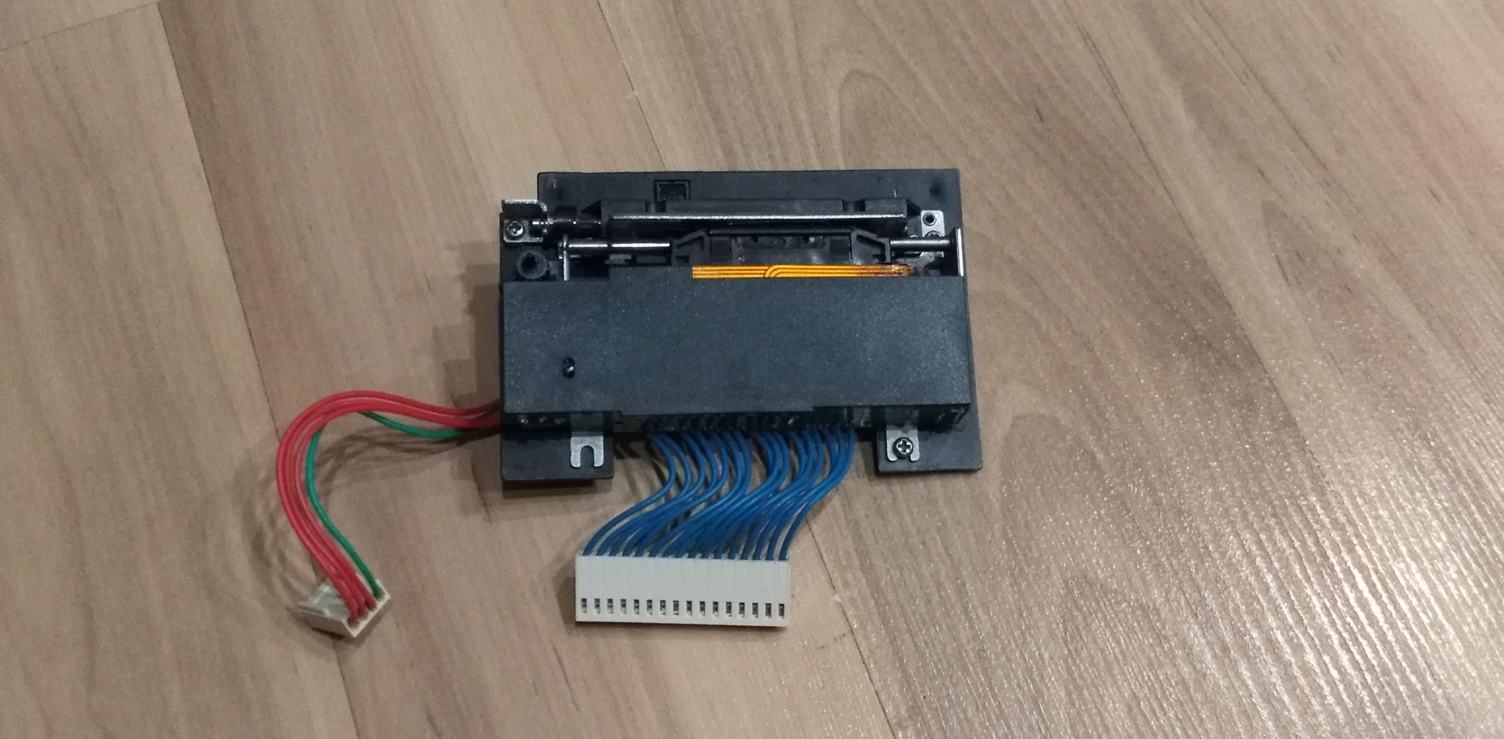
In the comments, people were interested in connecting a receipt printer. Having found the time out of its range, I finally figured out the printer. I started with the matrix. Model MD910, below the photo.

')
Well, since Arduinka, a soldering iron, and other things, have long since been waiting for their appearance on the scene, I decided to connect it to an untouchable person and print something. What is the most important thing in our life? This is a manual! And so I was puzzled by search of datasheet on this printer. Nuggul, the truth of the very first edition. There was a pinout pinout scheme, timings, a little about the printer device. There were no parameters for connecting the optocoupler's LED and several more data. The idea came to mind to ask this information in the cash register repair shops. Here, I’ll tell you, I was disappointed - these guys lazily stretched that they had no datasheets, service manuals or even cash registers, and in general they are busy here ...;)
And if you ask this information directly from the manufacturers themselves (Citizen Business Machines)? I did so — I wrote an email to them — so they say, and so, I'm a radio amateur, now I want to screw this printer and print leaflets on it, kindly and kindly provide a datasheet. And Citizen Systems Europe sent me filled-in information in a couple of days!
I assembled the sensor connection boards - there are two of them: Dot Pulse and Reset Pulse. Soldered the driver to control the engine and print head.
As for the drivers for the motor and the print head. There were several SMA4033 and STA471A microcircuits in the zagashniki , which were soldered out of the faulty Epson dot-matrix printer (of the FX800 type). Here are the vicissitudes of the fate of the microcircuits - the old dot-matrix printer was disassembled for parts, so that after a few years it would reincarnate into the appearance of a new printer! ;)
The documentation was found at the first Google request (by the way, I posted them on GitHub ). These chips are 4 Darlington transistors in a single package, the difference between them (except for supply voltages) in the presence of protective diodes in SMA4033. I really liked them - excellent parameters, you can glue on the radiator and just solder the wiring to the terminals, the case is relatively massive, so it can easily withstand the soldering with the help of a building dryer! ;)
How does the printer work?
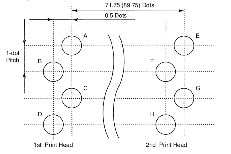
The print head consists of two identical parts. Each part includes four vertically standing needles. However, even and odd needles are slightly shifted relative to each other, I believe that they do not interfere with each other much - because the distance between them is quite tiny! However, this slightly complicates the printing algorithm: you first need to print odd dots, then, after waiting for the head to move 0.5 points, print even dots.

As for the two halves. The left part of the print head prints the first half of the line, the right - the second. To print a line of 8 pixels in height, you need to make two passes. Look, the first four columns of the letter A are printed for the first four bars. The first bar is typing points A and C, then 1 bar - the head is moved half a point, then B and D are printed, then it is shifted again by half a point. Then again, in four measures, the next column of the letter A is printed.

At the same time in the printer only 144 columns, 72 for each part of the print head. If we use the 8x8 font, then we will be able to type 18 characters in each line.
We found out how the printer prints. Now this business needs to be issued in the form of a program code.
What do we need to type the text?
1) input information - a string of 18 characters;
2) font
3) program
Most raster fonts are arranged as follows: each byte (or several bytes) describes one line of a character, the next one is the next line, and so on. This is convenient for displaying on the screen - since the image is built by row. In the case of printing, needles stand vertically. Therefore, we would be comfortable font, which is described in Stobltsy. However, I did not find this. I had to proceed from the fact that there is.
In addition, I decided to organize the printing as follows: the first step is to render the text lines to the buffer, the second step is to directly print the prepared information from the render buffer. It also gives some assurance that print timings will be respected. Writing the rendering code was the most difficult part of the program.
Let's see how rendering works.
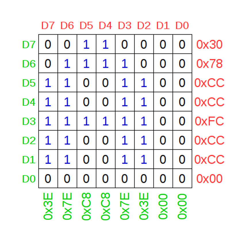
Here, the bits and bytes of the screen font are highlighted in red, the bits and bytes of the font for the printer are highlighted in green. The main task of rendering is to convert a screen font into a printer into a buffer. Processing looks like this: all D7th bits (all 8 bytes of the font) must be turned into bits D7-D0 (first column), all D6th bits need to be turned into bits D7-D0 (second column). Thus, the screen font for the Latin letter A (0x30, 0x78, 0xCC, 0xCC, 0xFC, 0xCC, 0xCC, 0x00) turns into a sequence (0x3E, 0x7E, 0xC8, 0xC8, 0x7E, 0x3E, 0x00, 0x00) for the render buffer. I hope that the following piece of code will help to understand the rendering algorithm.
I struggled with another big problem the whole evening: when I tried to work out the rendering code, garbage was thrown at the terminal, if I commented out this section, everything worked without problems. It seemed to me that the memory is full / rewritten and therefore there is garbage in the issue. After reading about the fact that Arduino stores all variables in RAM, I realized that all the fault is 2 kilobytes of font data. I had to store it directly in the body of the program (flash) and apply through special functions. It all worked. Here and here in more detail about it.
Another interesting surprise was presented to me by Xiaom Power Bank, which I planned to use as a power source. It simply did not turn on from the load in the form of Arduino, when forcibly turned on (by pressing the button) it turned on, fed the load for a couple of seconds, then was cut off. The reason - I think one: Arduinka does not consume so much, the motors and the print head (the main consumer) pulls in pulses, but not constantly (the load jumps from tens of milliamperes to a pair of amps) ...
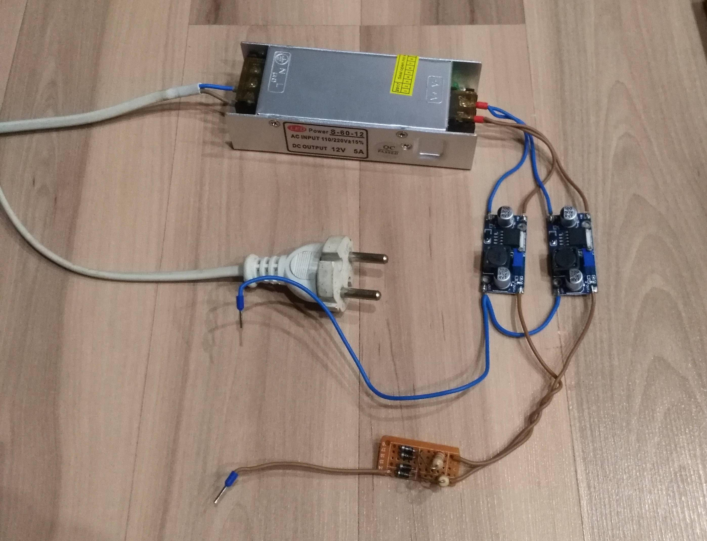
I had to fence the power supply unit from the 12 volt 5 amp power supply unit for the LED strip + 2 DC-DC converters on the LM2596 folk. I connected a Schottky diode + a 2.5 ohm resistor to limit the currents in the +5 volt output circuit.
Since the printer is a matrix printer, a tape cartridge is used for printing, yes, yes, as in the old days. I tried to try to restore the native cartridge, soaked it in water for a week. I tried to make out in order to soak the foam rubber with paint-mastic. The foam just crumbled ... The closest cartridge from me is in Samara. :(
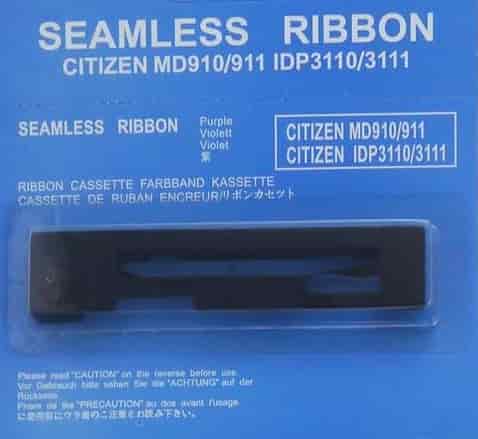
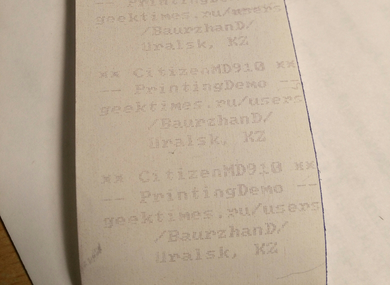
Then I decided to try to find a paper that is sensitive to shocks (when I bought it, the seller warned me a couple of times that this tape didn’t fit anywhere;) I had to reassure her that I understood everything, and then there would be no complaints from me ...;)) . I found only a tape 80 mm wide, I had to cut it into pieces and reduce the width to 57 mm, in a good old tube way with a ballpoint pen and ruler ... But it prints! ;)
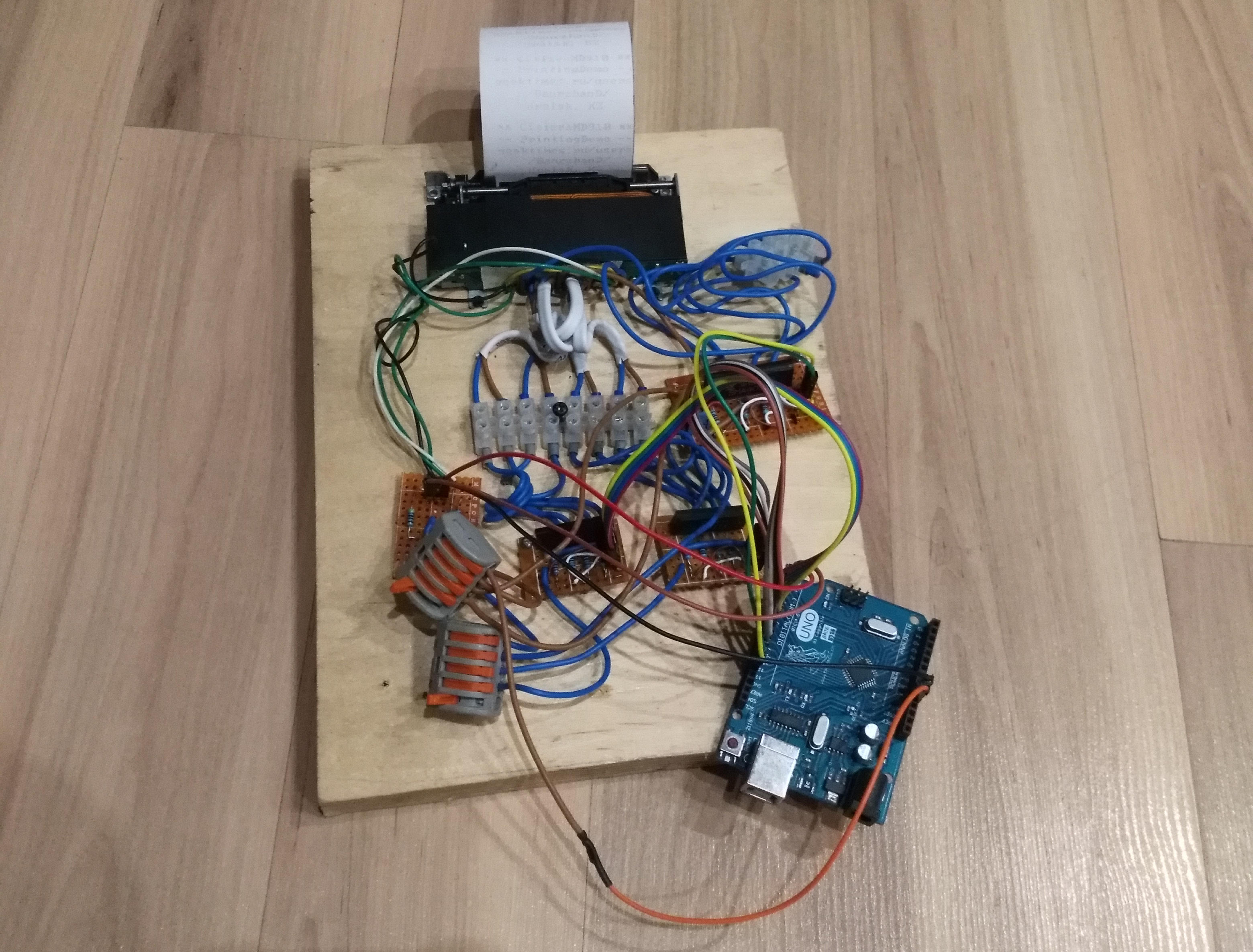
What does the final result look like? 20 mm plywood fixed printer and control boards. At installation, ShVVP 2 * 0.5mm, WAGO connectors and a terminal block are used! ;) MGTF ended a long time ago ... And I can not find it at all on sale in my city. :(
Video with a demonstration of the printer.
Thanks for attention!
In the comments, people were interested in connecting a receipt printer. Having found the time out of its range, I finally figured out the printer. I started with the matrix. Model MD910, below the photo.
')
Well, since Arduinka, a soldering iron, and other things, have long since been waiting for their appearance on the scene, I decided to connect it to an untouchable person and print something. What is the most important thing in our life? This is a manual! And so I was puzzled by search of datasheet on this printer. Nuggul, the truth of the very first edition. There was a pinout pinout scheme, timings, a little about the printer device. There were no parameters for connecting the optocoupler's LED and several more data. The idea came to mind to ask this information in the cash register repair shops. Here, I’ll tell you, I was disappointed - these guys lazily stretched that they had no datasheets, service manuals or even cash registers, and in general they are busy here ...;)
And if you ask this information directly from the manufacturers themselves (Citizen Business Machines)? I did so — I wrote an email to them — so they say, and so, I'm a radio amateur, now I want to screw this printer and print leaflets on it, kindly and kindly provide a datasheet. And Citizen Systems Europe sent me filled-in information in a couple of days!
I assembled the sensor connection boards - there are two of them: Dot Pulse and Reset Pulse. Soldered the driver to control the engine and print head.
Wiring diagrams sensors.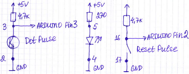
The numbers indicate to which printer pins these points are connected. Since the Arduino inputs are fed with inverted signals (for example, 1 if the switch is open), this point should be taken into account when writing the program.
The numbers indicate to which printer pins these points are connected. Since the Arduino inputs are fed with inverted signals (for example, 1 if the switch is open), this point should be taken into account when writing the program.
As for the drivers for the motor and the print head. There were several SMA4033 and STA471A microcircuits in the zagashniki , which were soldered out of the faulty Epson dot-matrix printer (of the FX800 type). Here are the vicissitudes of the fate of the microcircuits - the old dot-matrix printer was disassembled for parts, so that after a few years it would reincarnate into the appearance of a new printer! ;)
The documentation was found at the first Google request (by the way, I posted them on GitHub ). These chips are 4 Darlington transistors in a single package, the difference between them (except for supply voltages) in the presence of protective diodes in SMA4033. I really liked them - excellent parameters, you can glue on the radiator and just solder the wiring to the terminals, the case is relatively massive, so it can easily withstand the soldering with the help of a building dryer! ;)
Motor and Printhead Drivers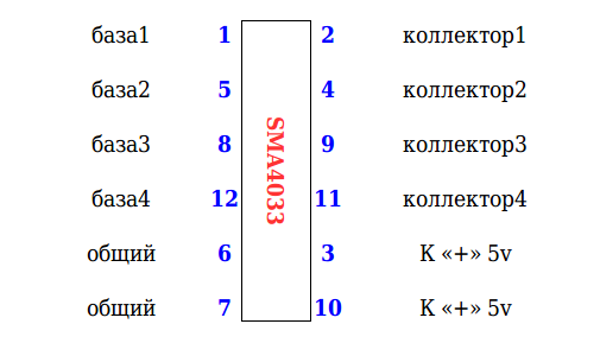
Wiring diagram of the motor. Only two channels of the four SMA4033 are used.
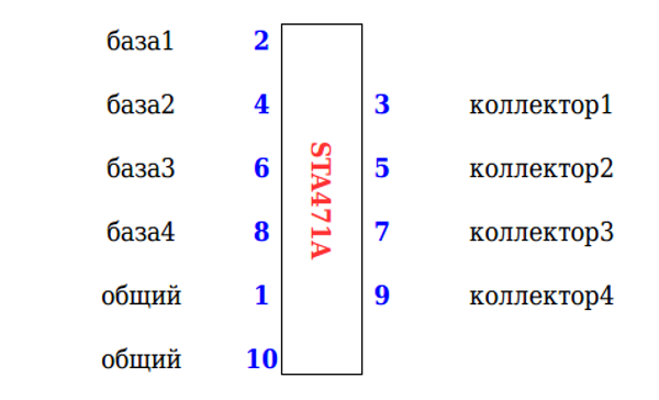
Wiring the print head to the chips STA471A (collectors). It must be remembered that the print head consists of 2 blocks of 4 needles. Therefore, we need 8 power outputs.
Common to both ICs. Output pins Arduino through resistors resistance (680 ohm - 1k) are connected to the base of Darlington transistors.
Wiring diagram of the motor. Only two channels of the four SMA4033 are used.
Wiring the print head to the chips STA471A (collectors). It must be remembered that the print head consists of 2 blocks of 4 needles. Therefore, we need 8 power outputs.
Common to both ICs. Output pins Arduino through resistors resistance (680 ohm - 1k) are connected to the base of Darlington transistors.
Printer pinout layout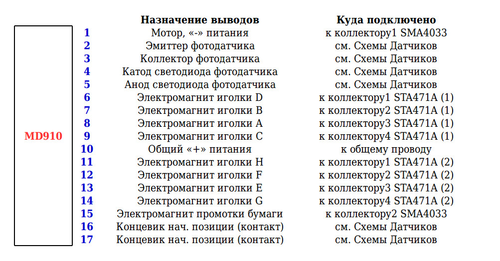
How is all this connected to Arduine?
#define b1stHead_D 8 #define b1stHead_B 9 #define b1stHead_A 10 #define b1stHead_C 11 #define b2ndHead_H 4 #define b2ndHead_F 5 #define b2ndHead_E 6 #define b2ndHead_G 7 #define Motor 13 #define Feed 12 #define DotPulse 3 #define ResetPulse 2 How does the printer work?
The print head consists of two identical parts. Each part includes four vertically standing needles. However, even and odd needles are slightly shifted relative to each other, I believe that they do not interfere with each other much - because the distance between them is quite tiny! However, this slightly complicates the printing algorithm: you first need to print odd dots, then, after waiting for the head to move 0.5 points, print even dots.
As for the two halves. The left part of the print head prints the first half of the line, the right - the second. To print a line of 8 pixels in height, you need to make two passes. Look, the first four columns of the letter A are printed for the first four bars. The first bar is typing points A and C, then 1 bar - the head is moved half a point, then B and D are printed, then it is shifted again by half a point. Then again, in four measures, the next column of the letter A is printed.
At the same time in the printer only 144 columns, 72 for each part of the print head. If we use the 8x8 font, then we will be able to type 18 characters in each line.
We found out how the printer prints. Now this business needs to be issued in the form of a program code.
What do we need to type the text?
1) input information - a string of 18 characters;
2) font
3) program
Most raster fonts are arranged as follows: each byte (or several bytes) describes one line of a character, the next one is the next line, and so on. This is convenient for displaying on the screen - since the image is built by row. In the case of printing, needles stand vertically. Therefore, we would be comfortable font, which is described in Stobltsy. However, I did not find this. I had to proceed from the fact that there is.
In addition, I decided to organize the printing as follows: the first step is to render the text lines to the buffer, the second step is to directly print the prepared information from the render buffer. It also gives some assurance that print timings will be respected. Writing the rendering code was the most difficult part of the program.
Let's see how rendering works.
Here, the bits and bytes of the screen font are highlighted in red, the bits and bytes of the font for the printer are highlighted in green. The main task of rendering is to convert a screen font into a printer into a buffer. Processing looks like this: all D7th bits (all 8 bytes of the font) must be turned into bits D7-D0 (first column), all D6th bits need to be turned into bits D7-D0 (second column). Thus, the screen font for the Latin letter A (0x30, 0x78, 0xCC, 0xCC, 0xFC, 0xCC, 0xCC, 0x00) turns into a sequence (0x3E, 0x7E, 0xC8, 0xC8, 0x7E, 0x3E, 0x00, 0x00) for the render buffer. I hope that the following piece of code will help to understand the rendering algorithm.
I struggled with another big problem the whole evening: when I tried to work out the rendering code, garbage was thrown at the terminal, if I commented out this section, everything worked without problems. It seemed to me that the memory is full / rewritten and therefore there is garbage in the issue. After reading about the fact that Arduino stores all variables in RAM, I realized that all the fault is 2 kilobytes of font data. I had to store it directly in the body of the program (flash) and apply through special functions. It all worked. Here and here in more detail about it.
Buffer Render Code
// FontData=pgm_read_byte(&(CP1251Font[Address])); // https://www.arduino.cc/reference/en/language/variables/utilities/progmem/ // 1 // http://www.nongnu.org/avr-libc/user-manual/pgmspace.html // 18 (144 / 8) +1 = 19 void MD910_RenderPrintStr(char String2Print[19]) { byte TmpVal[8], MaskBit[8]; byte i,j,k, Code, Column, Value; word FontStart; //*************************************************************** Column=0; // MD910_Buffer[] for(j=0;j<=17;j++) // { Code=byte(String2Print[j]); FontStart=Code*8; // , CP1251Font[] for (k=0; k<=7; k++) { TmpVal[k]=pgm_read_byte(&(CP1251Font[FontStart+k])); // (0) }; for(i=0;i<=7;i++) { for (k=0; k<=7; k++) { MaskBit[k]=(TmpVal[k] & 128) >> k; // (1) }; Value=0; for (k=0; k<=7; k++) { Value=(Value | MaskBit[k]); // (2) }; MD910_Buffer[Column]=Value; // (3) for (k=0; k<=7; k++) { TmpVal[k]=TmpVal[k] << 1; // (4) }; Column++; // }; }; //*************************************************************** }; Print buffer code
void MD910_PrintBuffer() { byte PinA, PinB, PinC, PinD, PinE, PinF, PinG, PinH; Serial.println("Printing...."); //*********************************************************************************************************** DP_Count=0; // *************************** if (RP_Status()==false) { for(byte j=0;j<=71;j++) { PinA=MD910_Buffer[j] & 0x80; PinB=MD910_Buffer[j] & 0x40; PinC=MD910_Buffer[j] & 0x20; PinD=MD910_Buffer[j] & 0x10; PinE=MD910_Buffer[j+72] & 0x80; PinF=MD910_Buffer[j+72] & 0x40; PinG=MD910_Buffer[j+72] & 0x20; PinH=MD910_Buffer[j+72] & 0x10; // 1 // A,C E,G () if (PinA>0) digitalWrite(b1stHead_A, HIGH); // if (PinC>0) digitalWrite(b1stHead_C, HIGH); // if (PinE>0) digitalWrite(b2ndHead_E, HIGH); // if (PinG>0) digitalWrite(b2ndHead_G, HIGH); // while (DP_Status()==true) {}; while (DP_Status()==false) {}; DP_Count++; digitalWrite(b1stHead_A, LOW); digitalWrite(b1stHead_C, LOW); digitalWrite(b2ndHead_E, LOW); digitalWrite(b2ndHead_G, LOW); while (DP_Status()==true) {}; while (DP_Status()==false) {}; DP_Count++; // 2 // B,D F,H () if (PinB>0) digitalWrite(b1stHead_B, HIGH); // if (PinD>0) digitalWrite(b1stHead_D, HIGH); // if (PinF>0) digitalWrite(b2ndHead_F, HIGH); // if (PinH>0) digitalWrite(b2ndHead_H, HIGH); // while (DP_Status()==true) { }; while (DP_Status()==false) { }; DP_Count++; digitalWrite(b1stHead_B, LOW); digitalWrite(b1stHead_D, LOW); digitalWrite(b2ndHead_F, LOW); digitalWrite(b2ndHead_H, LOW); while (DP_Status()==true) {}; while (DP_Status()==false) {}; DP_Count++; }; } while (RP_Status()==false) {}; // while (RP_Status()==true) {}; // // *************************** if (RP_Status()==false) { for(byte j=0;j<=71;j++) { PinA=MD910_Buffer[j] & 0x08; PinB=MD910_Buffer[j] & 0x04; PinC=MD910_Buffer[j] & 0x02; PinD=MD910_Buffer[j] & 0x01; PinE=MD910_Buffer[j+72] & 0x08; PinF=MD910_Buffer[j+72] & 0x04; PinG=MD910_Buffer[j+72] & 0x02; PinH=MD910_Buffer[j+72] & 0x01; // 1 // A,C E,G () if (PinA>0) digitalWrite(b1stHead_A, HIGH); // if (PinC>0) digitalWrite(b1stHead_C, HIGH); // if (PinE>0) digitalWrite(b2ndHead_E, HIGH); // if (PinG>0) digitalWrite(b2ndHead_G, HIGH); // while (DP_Status()==true) {}; while (DP_Status()==false) {}; DP_Count++; digitalWrite(b1stHead_A, LOW); digitalWrite(b1stHead_C, LOW); digitalWrite(b2ndHead_E, LOW); digitalWrite(b2ndHead_G, LOW); while (DP_Status()==true) {}; while (DP_Status()==false) {}; DP_Count++; // 2 // B,D F,H () if (PinB>0) digitalWrite(b1stHead_B, HIGH); // if (PinD>0) digitalWrite(b1stHead_D, HIGH); // if (PinF>0) digitalWrite(b2ndHead_F, HIGH); // if (PinH>0) digitalWrite(b2ndHead_H, HIGH); // while (DP_Status()==true) { }; while (DP_Status()==false) { }; DP_Count++; digitalWrite(b1stHead_B, LOW); digitalWrite(b1stHead_D, LOW); digitalWrite(b2ndHead_F, LOW); digitalWrite(b2ndHead_H, LOW); while (DP_Status()==true) {}; while (DP_Status()==false) {}; DP_Count++; }; } while (RP_Status()==false) {}; while (RP_Status()==true) {}; //*********************************************************************************************************** Serial.println("Done!"); } Another interesting surprise was presented to me by Xiaom Power Bank, which I planned to use as a power source. It simply did not turn on from the load in the form of Arduino, when forcibly turned on (by pressing the button) it turned on, fed the load for a couple of seconds, then was cut off. The reason - I think one: Arduinka does not consume so much, the motors and the print head (the main consumer) pulls in pulses, but not constantly (the load jumps from tens of milliamperes to a pair of amps) ...
I had to fence the power supply unit from the 12 volt 5 amp power supply unit for the LED strip + 2 DC-DC converters on the LM2596 folk. I connected a Schottky diode + a 2.5 ohm resistor to limit the currents in the +5 volt output circuit.
Since the printer is a matrix printer, a tape cartridge is used for printing, yes, yes, as in the old days. I tried to try to restore the native cartridge, soaked it in water for a week. I tried to make out in order to soak the foam rubber with paint-mastic. The foam just crumbled ... The closest cartridge from me is in Samara. :(
Then I decided to try to find a paper that is sensitive to shocks (when I bought it, the seller warned me a couple of times that this tape didn’t fit anywhere;) I had to reassure her that I understood everything, and then there would be no complaints from me ...;)) . I found only a tape 80 mm wide, I had to cut it into pieces and reduce the width to 57 mm, in a good old tube way with a ballpoint pen and ruler ... But it prints! ;)
What does the final result look like? 20 mm plywood fixed printer and control boards. At installation, ShVVP 2 * 0.5mm, WAGO connectors and a terminal block are used! ;) MGTF ended a long time ago ... And I can not find it at all on sale in my city. :(
Video with a demonstration of the printer.
Source text, fonts, useful utilities, documentation
Thanks for attention!
Source: https://habr.com/ru/post/374395/
All Articles