Pneumonia and steampunk wet dreams
“Pneumatic automation is becoming more and more important for modern technology every year. Pneumatic devices are widely used in the automation of production processes and in the management of power plants ”
LA Zalmanzon Pnevmonika. Jet pneumatic automation. ed. Science, M. 1965
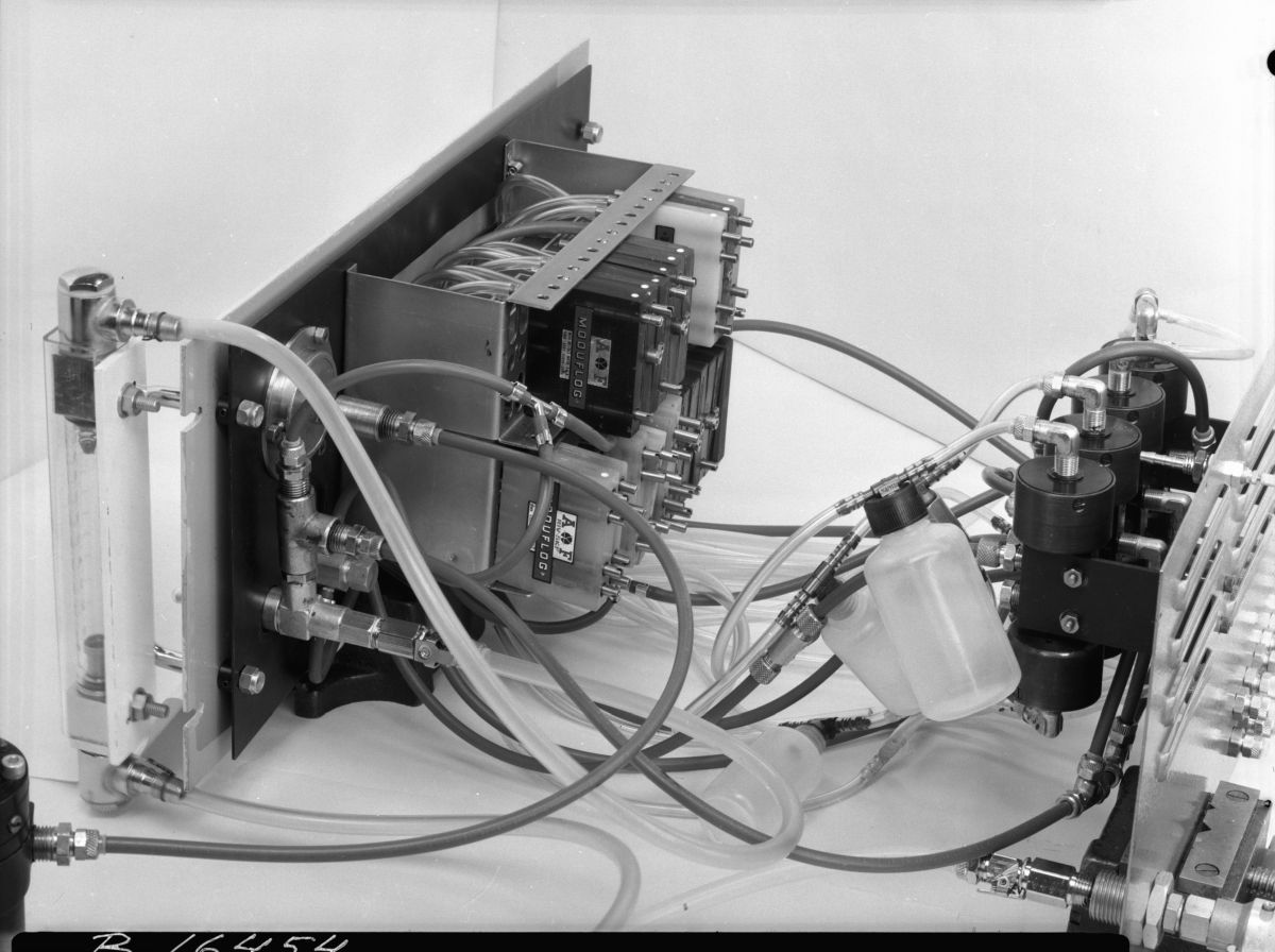
Figure 1: Fluidic Kit by Tekniska musee
Suppose we decided to score on the assembly of a computer on reed relays and do even more insane things. For those who follow the assembly BrainfuckPC - do not worry, he is not in danger. I just make plans for the future.
Introduction
Do you know what the effect of sticking a jet to the wall? Let's go with you to the bathroom, after taking a tablespoon with you:
Figure 2: Jet Sticking Effect
We see how a jet of water coming into contact with the hump of a spoon immediately sticks to its wall, noticeably bent. This phenomenon has been known for a long time and has been described by many researchers, including such prominent ones as Jung and Reynolds. Its name is “Coanda Effect”, but this phenomenon was named after the Romanian inventor who worked in France, Henri Coanda, who at the beginning of the last century proposed using it for a number of technical applications.
Directorial version of the article for visuals
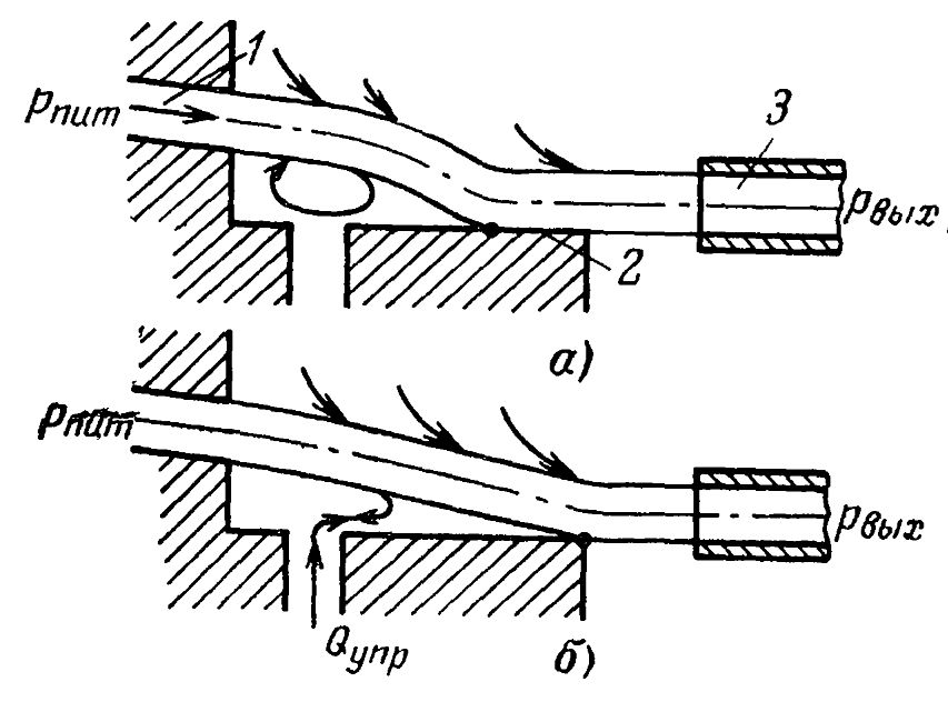
Figure 3: Effect of jet attraction to the wall (Coanda effect)
The essence of this phenomenon in a simplified form is as follows: a jet of working medium flowing from the power nozzle 1 at an angle to the wall 2 touches it at a certain point and ejects gas (air) from the zone bounded by the jet and the wall.
Figure 4: Creating a vacuum zone between the jet and the wall
As a result, in this zone, a reduced pressure is created and the jet is sucked into the wall, occupying a stable position. If the receiving nozzle 3 is installed at the wall level, then a pressure Pout will arise in it corresponding to the pressure in channel 1. By transferring the working medium from the control nozzle to the zone of reduced pressure, the main jet will detach from the wall.
If in the new position the jet touches the second wall properly installed, then due to the sticking phenomenon it will remain in this new position even after the control signal has ceased. We did nothing more than a controlled bistable element.
Figure 5: Switching the bistable element
This bistable element when switching on can take any position. Adding asymmetry to the element design, we will make the element monostable — if none of the signals are given, it will always assume exactly one stable state.
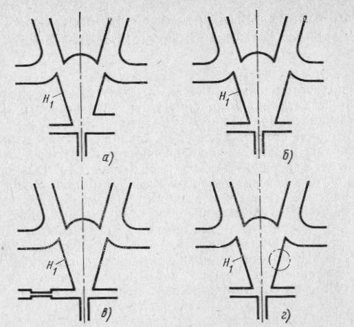
Figure 6: Monostable element with jet sticking to the wall. Monostability is provided by the unequal length of the attracting walls (a), the unequal displacement of the attracting walls (b), the unequal input resistances of the control channels (c), the presence of a hole in one of the plates (d).

Figure 7: monostable element operation
Inkjet elements
With the effect itself more or less sorted out. I did not go into the theoretical details of the laminar and turbulent flow. This is a topic of separate research and LGA simulations in OpenFOAM. To implement a computer, we first need basic logic elements.
Logic element 2IL / 2OR-NOT
Let's take our initial scheme, but from the side of stable output the control input will have two underwater tubes - A and B.
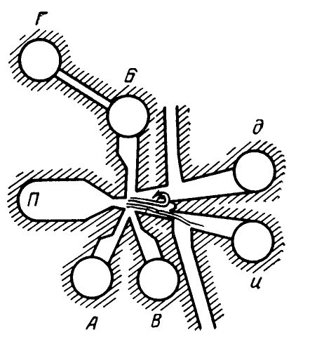
Figure 8: The basic element on the effect of sticking of the jet to the wall
What will happen if we start to supply air to at least one of them? That's right, at output d we get the result of operation 2IL. At the output u, there is the result of operation 2ILE.
Since 2ILI-NOT, or “Pierce's arrow” forms the basis for the space of Boolean functions of two variables, it is possible to assemble absolutely any logical circuit on the elements of this type.
Logic Element 2I / Exclusive OR
However, one arrow will not be enough - the schemes on one type of element are quite redundant.

Figure 9: Logic Element And
Inkjet logical element And in two variations. In Figure b), pressure will appear in the output nozzle only if signals are given to both inputs. In the case of only one of the entrances - the jet will stick to one of the walls - H1 or H2 and will not fall on the exit. Figure c) is a slightly more interesting construct. Here, each of the inputs is controlling for the other jet. If there is only one of the signals, the jet will go to exit a or b. When both streams are present, each deflects the other onto the adhering walls W1 and W2, thereby the flow begins to exit a * b.
Since these elements are self-powered - they do not have a power nozzle - they cannot be converted into a full 2I-NOT, because in the absence of both input signals, no output will “sniff”. On the other hand, they will perfectly go beyond the EXCLUSIVE OR - we merge a + b into one channel and get the desired result.
Memory cell
For a computer, it is important to save data for work - at least registers are required, as is maximum RAM and ROM.
With a temporary memory cell, everything is quite simple - we take element 2IL or connect one of the inputs to output d. Get an item with positive feedback. As soon as we give a signal to output A, as the element switches, from jet d the jet will start to flow to input B and the cell will remain in this state until the supply of the jet power stops. Or we can apply a jet to the input B or D and turn off the element.
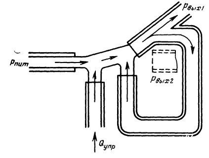
Figure 10: Jet interaction with positive feedback.
Permanent memory can be organized using two media.
One medium - a liquid - can take one position from two:
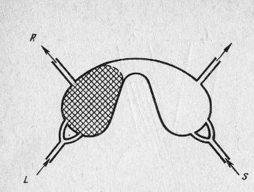
Figure 11: Inkjet with memory. Letters denote the flows that implement the operations of memory insertion S, memory reset L, reading R.
By applying pressure to the input S or L, we can move a drop of fluid between the chambers. And estimating the closed or open channel R - we can read data from the cell.

Figure 12: Control Option. When the outlet is closed, the pressure will go to the atmospheric window. There may well be a reading circuit.
Another option is to apply a small pressure to the input L, which is insufficient to switch the state of the memory cell. The output of R will either “siphon” or not.
Such an element, of course, works only at a certain position in space.
Pulse generator
If we connect a closed camera to the output u, then we get a pulse generator. As long as the pressure in the chamber is less than critical, the stream of air through the channel U continues to flow into the tank. When exceeded - the pressure of the chamber squeezes the jet, literally blows it out of the channel u and tears it from the wall, as a result of which it begins to flow into the channel d. At the same time, the jet coming out of the tank has been working as a control for some time. Also, air is ejected from the reservoir. Gradually, the pressure in the tank drops and the jet returns to its original state. The cycle repeats.
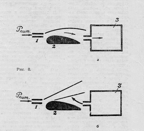
Figure 13: Pulse generator principle
The frequency of the pulses depends on the pressure in the system and the volume of the chamber. I do not know the exact numbers, but you can squeeze 1kHz.
Existing pneumistor and pneumatic components
A small overview of existing and existing elements of pneumatics. In the first place - pneumatic automation, which is actively used so far. At the heart of - banal valve and all there membranes.
One of the options - two-piston elements. We play with inputs - we get various logical operations at the output.
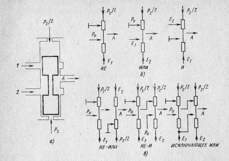
Figure 14: Double Piston Elements. and - the design element. b - logical circuits with one dual-piston element (NOT, OR, AND), c - logical circuits with two dual-piston elements (NOT-OR, NOT-AND, excluding OR). ½ p2 is the return pressure, p0 is the constant pressure at the outlet.
Another variation is Membranes and Cameras. They are easier to assemble (layers of the body - a membrane layer) and ensure the tightness of the chambers. The reliability of the operation of the two-piston elements strongly depends on the gaps between the pistons and the cylinder.
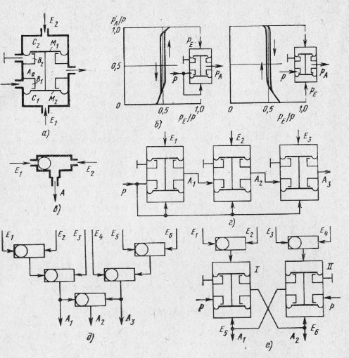
Figure 15: Two-Membrane Element. a - design, b - principle of switching of a two-membrane element. c - logical element OR, g - I, d - multiple logical scheme OR, e - bistable trigger cascade, M1 and M2 - membranes, A0, B1, B2, C1, C2 - cameras.
Universal system of elements of industrial pneumatic automation (USEPPA)
In the 1960-61-ies, in the USSR, a set of structurally completed unified pneumatic elements designed to build devices and pneumatic automation systems was developed. Each element performs a certain elementary operation (amplification, repetition; comparison, memorization, etc.).
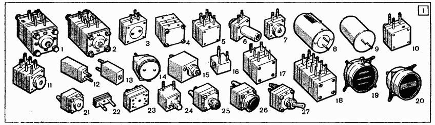
Figure 16: a set of USEPP 1,2 elements - two and four-input amplifiers, 3 - a coarse powerful repeater; 4.17, 23 - pneumorel (in different designs); 5, 10 - valves (unloaded, unloaded); 6 - precise repeater with a shift; 7 - accurate follower; 8.9 - pneumatic capacitance (adjustable and unregulated); 11 - continuous signal memory; 12 - setting devices; 13, 14 - pneumatic resistance (constant, adjustable); 15 - throttle adder; 16, 22 - double non-return valve (ball, with a flying disc); 18 - discrete signal memory; 19, 20 - indicators (blinkers); 21 - limit switch; 24, 25, 26 - pneumatic buttons; 27 - pneumotumboiler
In various combinations, USEPPA elements are used in the construction of regulators, automatic optimization systems, start-up, shutdown, protection and blocking devices, cyclic automatic systems, telemechanics devices, and others. Pneumatic automation devices are assembled from USEPPA elements on boards; all connections between the elements are made using pneumatic channels inside the boards.
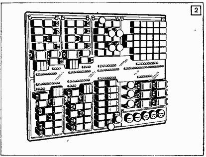
Figure 17: General view of the pneumatic control system at USEPPA
The functionality of USEPPA allows realizing continuous, discrete and continuous-discrete operations. For the implementation of continuous (analog) operations on pneumatic signals, use the elements of comparison (amplifiers) for two and four inputs, various repeaters, fixed and variable pneumatic capacitances, unregulated and adjustable pneumatic resistances. With their help, pneumatic decisive amplifiers and inertial links are created, which form the basis of analog pneumatic engineering.
For the construction of discrete (relay) pneumatic devices, universal pneumorelles and a double non-return valve are used ;: elementary logical operations are performed with their help. Temporary operations in relay circuits are carried out using natural delays (inertial links) and forced delays from discrete pneumatic signals. Continuous discrete operations are performed using pneumatic valves, elements with memorizing continuous signals and linear pulsating resistances. These elements work with both continuous and discrete signals and can significantly expand the possibilities of building devices for pneumatic automation. The USEPPA also includes auxiliary elements - various actuators, pneumatic buttons, pneumotumboilers, pnevmoelektro-and elektropnevmoimpereobrazovateli, etc.
Based on USEPPA in the USSR in the 60s. created a system of universal pneumatic devices, called "Start". It is adapted for building mainly branched systems for stabilization and optimization of continuous technological processes. To create automated control systems for continuous technological processes (APCS), an aggregate functional-instrumental complex of pneumatic means “Center” (the beginning of the 1970s) is used. It consists of large functional blocks assembled from USEPA elements.
For the construction of discrete control systems of cyclic and periodic processes in the early 70s. an aggregate system of sub-blocks “Cycle” was created. This system uses a modernized element base USEPPA (except for elements with elastic and moving parts in the system jet elements are used); all its blocks and devices are mounted in standard containers, cabinets, consoles, etc. USEPA and Start were awarded the Lenin Prize (1964), the Center complex was awarded the USSR State Prize (1974).
Glushkov V.M., Amosov N.M., Artemenko I.A. Encyclopedia of cybernetics. Volume 2. Kiev, 1974
What is most interesting, these elements are produced and used to this day . I will be glad to examples in the comments in which areas of the technology is used.
Elements of the Volga jet system
I prefer these guys to play on a 3D printer. The valve is not that. Yet the stream of air is where the magic is.
Volga inkjet systems have been developed at the Volzhsky branch of VNIIMASH and are based on aerodynamic effects such as jet jets, jet sticking to a solid wall and internal feedback. They are divided into discrete inkjet elements, designed to implement various combinations of logical functions NOT, OR, A and inkjet analog elements used to compare and amplify input signals.

Figure 18: The appearance and construction of the element of the sei Volga
The pneumatic element has a supply channel 1, always connected to a pressure pneumatic line, the pressure in which is p 0.02 ... 0.03 MPa, four control channels 2, 3, 6 and 7 and two output channels: output "OR" - 5 and output "NOT OR "- 4. The working chamber of the pneumoelement is formed by the divider A and the diffuser B. The working chamber receives the main air flow through a nozzle connected to supply channel 1, and control jets through corresponding nozzles connected to channels 2, 3, 6 and 7. To ensure normal operation, the pneumatic element has ventilation chambers C open to the atmosphere.
')
In the pneumatic element, the axis of the nozzle connected to the supply channel 1 is offset relative to the axis of the diffuser B so that the air stream supplied through the nozzle, in the absence of control signals, always “sticks” to the right wall of the diffuser B and gets into the output channel 4. When the control signal At inputs 2 and 3 or both of these inputs, the main air flow is transferred to the opposite wall of the diffuser B and enters the output channel 5. Thus, the logical operation "OR" is realized. After removing the control signals, the air flow returns to the original direction and re-enters channel 4.
The control signals received via channels 6 and 7 are prohibitive, i.e., if they are present, there will be no signal on output channel 5, even if there are control signals in channels 2 and 3.
The pneumatic element CT-55 is a basic element. Using several such elements and changing the combinations of the compounds of its output pneumatic lines, any logical functions can be realized.
The appearance of the element "Volga" is shown in Fig. 12.10, b. Structurally, the elements of the Volga system are a combination of two plastic plates, on which, for example, the grooves are formed by stamping, corresponding to a specific pattern (Fig. 12.10, a). If you connect (glue) two plates with a mirror-like arrangement of the grooves, then in such a detail corresponding chambers and channels are formed, ending with cylindrical nipples on which plastic tubes of external pneumatic lines are worn.
In order to increase the compactness and reduce the number of plastic connecting tubes, several elements of the Volga system form blocks. In this case, the elements are mounted on a common circuit board. The nipples of each element are inserted into the corresponding holes of the circuit board, which are connected by a specific circuit using internal channels. This design is simple and technological, which ensures the low cost of inkjet elements and control units built with their use.
Lepeshkin A.V., Mikhaylin A.A., Sheipak A.A. Hydraulics and hydropneumatic: Tutorial. Part 2. Hydraulic machines and hydraulic pneumatic actuator / Ed. A.A. Shapek. - M .: MGIU, 2003. - 352 p.
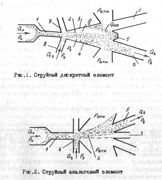
Figure 19: Inkjet discrete and analog element in the base of the pneumistors of the series "Volga"
I have a whole album of these elements.
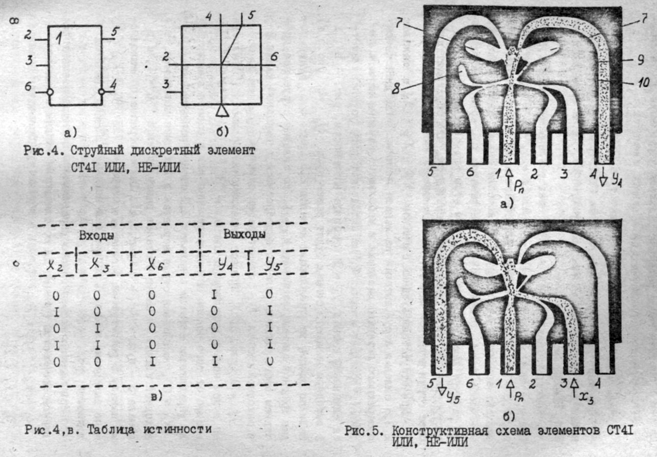
Figure 20: CT41 - OR NOT
Also the basic element on which you can implement everything else.
The album has the following elements:
- CT42 - trigger
- CT43 - 2I-NOT,
- CT44 - 3ILI-NOT,
- CT45 - 2ILI-NOT with a self-blocking channel (probably)
- CT53 - 6ILI-NOT,
- CT54 - 8IL
- CT55 - 2NOR + 2OR-NOT
- CT56 - RS-trigger
- CT57 - 4ILI-NOT
- CT60 - 2I + 2IL
There are still analog inkjet elements, I will not list them anymore. Who cares - well directly to the album itself.
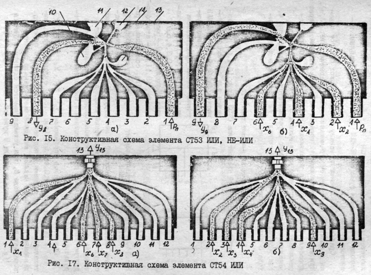
Figure 21: Construction diagram of the elements of the ST53 and ST54
Comparative characteristics of elements
(Which no one will find, but many people remember)
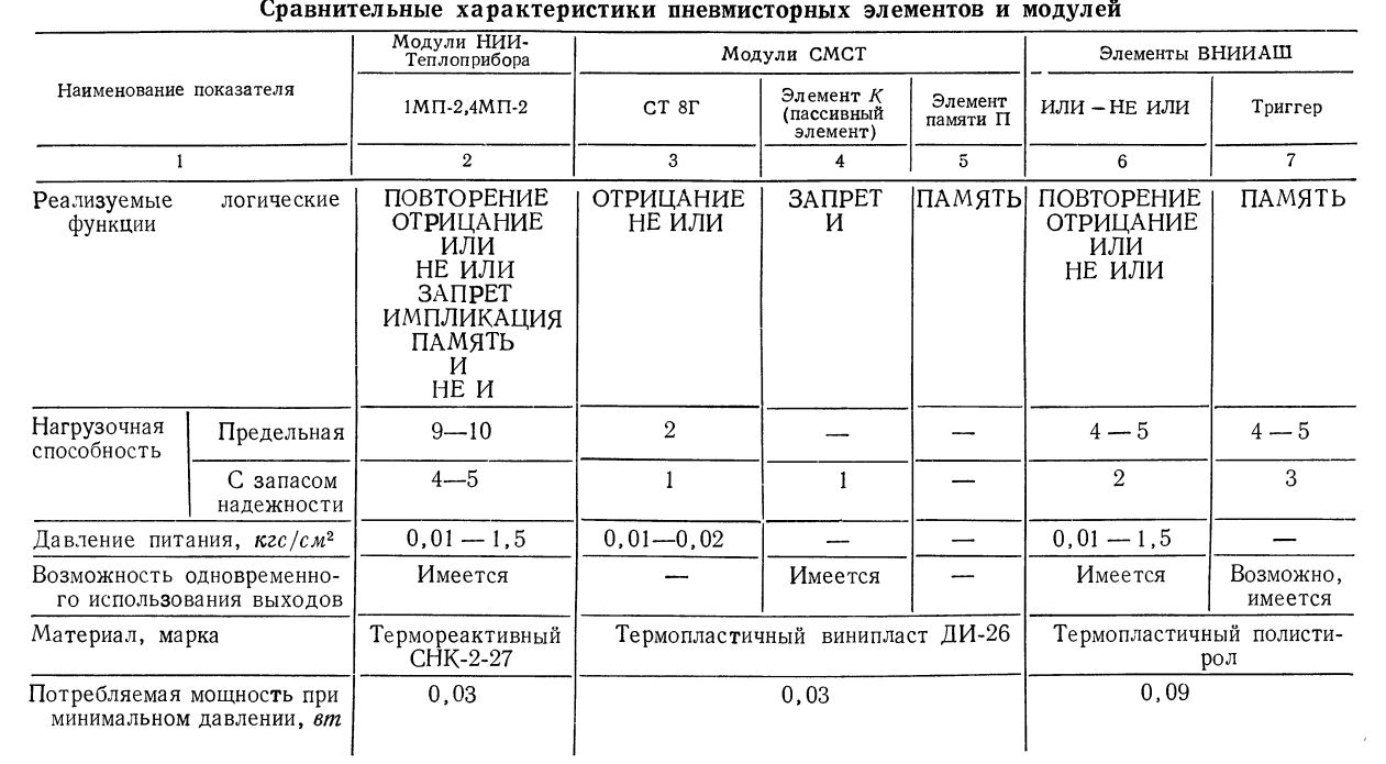
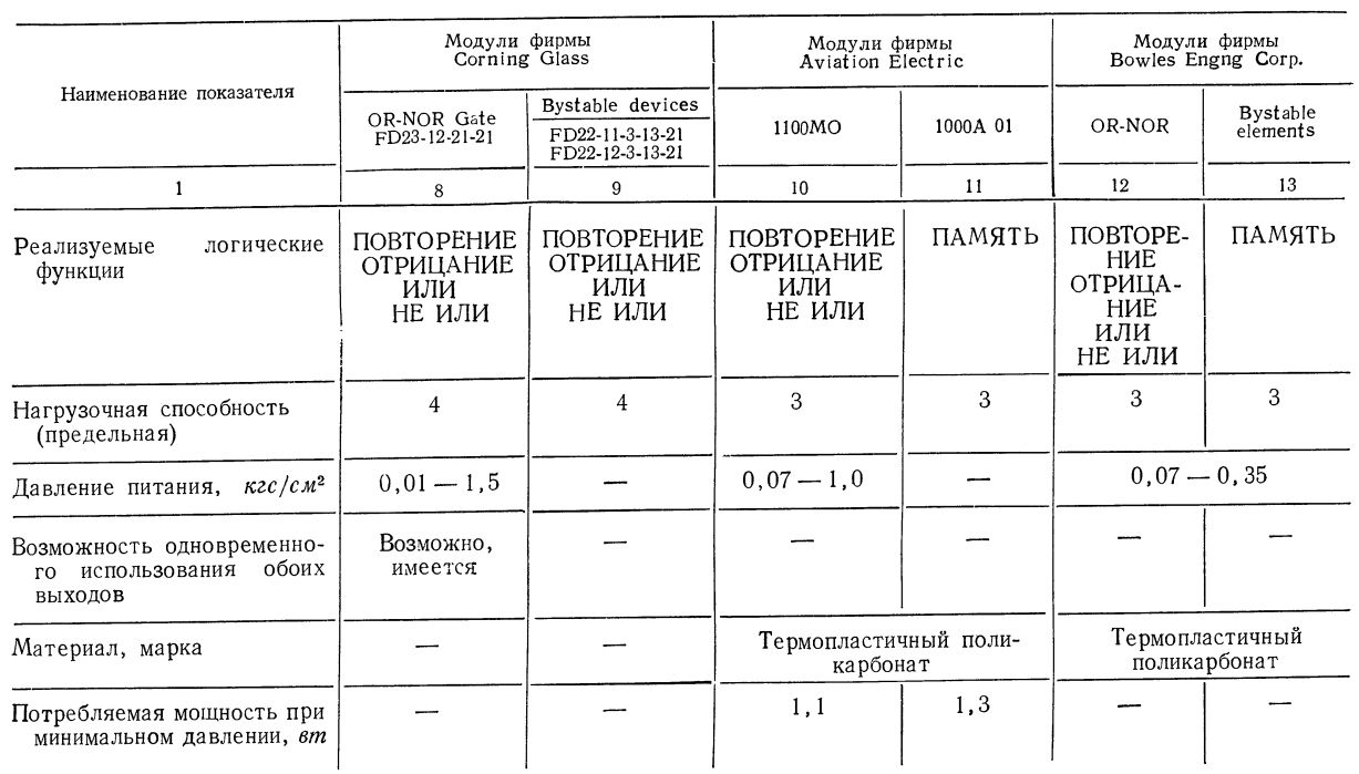
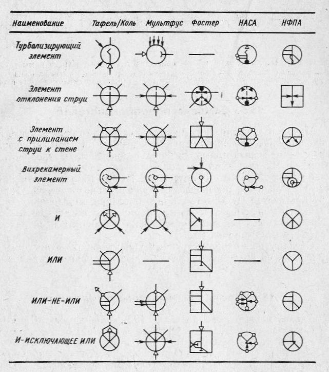
For reference, I give the comparison tables of pneumistors of various manufacturers.
Domestic:
And foreign:
Scheme
With logical elements sorted out. Consider what can be done on their basis.
Basic element
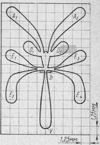
Figure 22: Base element with jet sticking to wall. V - power channel. E1- E4 - control channels. O1-O2 atmospheric channels, A1, A2 - output channels. Grid for understanding sizes
Reversible counter
Since the architecture of my relay computer is close to me, first of all it is important for me to have reversible counters. There are such. Based on the base item.
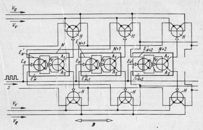
Figure 23: Inkjet shift register with symmetrically gated trigger stages for two shear directions (forward and reverse counter). H - jet elements with jet sticking to the wall as shear direction switches. Vv Vr - inputs for signals defining the direction of shift, D - direction of shift, N, N + 1, N + 2 - blocks of memory. E0 - inputs for shift pulses. E '' inputs for parallel input of signals into memory and output from memory.
Adder
In addition to the counter is desirable adder. Elements I. are already needed here. Their central channel is used to calculate the next discharge, and the side channels are used for the current one.
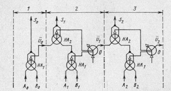
Figure 24: Schematic diagram of the adder
Legend
Nowadays
It seems that you can even create an inkjet computer ... In fact - nothing complicated - we resurrect a couple of basic elements, debug them and design complex complex systems with a bunch of tubes. Everyone remembers pictures of quantum computers?
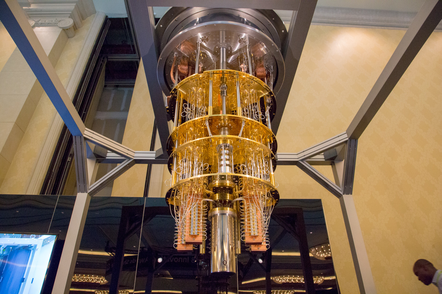
Figure 25: Some part of a quantum computer
Several small modules and a huge column strapping? Inkjet computer will look something like this. Only one compressor with a drive of which will cost.
On the other hand, on the 20x20cm panel, you can safely place almost a hundred basic logic elements! And then we collect these panels in a pile and we get a rather compact system.
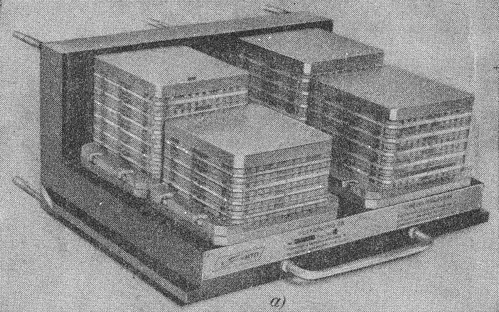
Figure 26: A Sandwich That May Come Out
In addition to the elements, we place through holes on the panel to connect the levels between each other and interleave panels with channels, like conductors on a printed circuit board. A layer of logic panel, a couple of layers of jumpers. With a thickness of each layer of 4-5 mm, and, say, 2 layers of jumpers for each layer of logic, we get 15 mm per 100 basic elements. On ten panels of logic, we get a sandwich of 1000 elements with a nominal size of 200x200x200 mm. Yes, I have a relay computer of 700 relays!
The truth here will have to organize the registers and memory on the same relay. Accordingly, much more elements will be required - 5-6 thousand pieces. But if the panels are ordered by casting under pressure from the Chinese - then why not? Jumper layers print ...
I plan to use DipTrace to design the circuits. Essentially we draw elements so that the layers can be imported into fusion 360 and extrude the channels and windows.
The correctness of the logic scheme will be given to CADs - you can also draw a scheme of almost ordinary logic elements, and then the layout.
Classic "Why ???? 777"

Figure 27: The Classic Then
Well, imagine - a large stand, front blinkers and flags, behind - a perforated wall for atmospheric windows. We start the steam generator, the steam begins to flow into the car, the blinkers begin to move in front, and behind the steam from the holes of the chukh-chukh-chukh. Beauty...
In any case, I have so far at the beginning of the path and only collect information. There is no idea of the architecture of the future machine, or its properties, nothing ... But you know what is most interesting? People do this!
Comrades from IPU RAS, for example, have created a library of inkjet elements and software for the development of systems of inkjet logic :
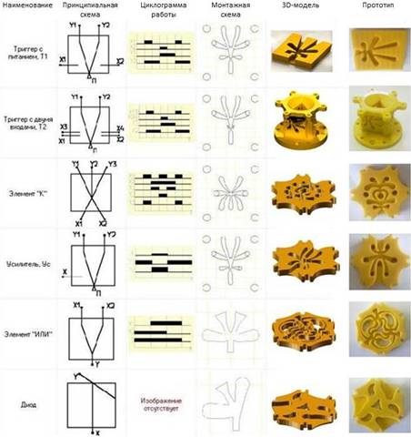
Figure 28: Example of a database of inkjet elements
In fact, the guys have already done what I want - they drew the elements in CAD and printed them on the printer. Sorry for the mail does not respond)
Here is a more realistic task - a gas-static bearing control system :
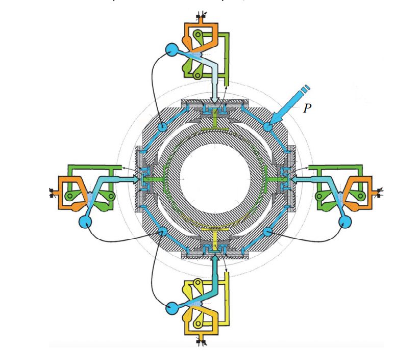
Figure 29: Four-channel inkjet control system with discrete controllers with independent control channel for each segment. P is the supply pressure of gas-static bearings. Things didn't get to 3D printing ..
Of course, where there is a gas jet, jet logic may well be used there. For example in the engine of the D-18 aircraft AN-124 "Ruslan"
About the applicability of pneumatic systems, I just know that this is a very common thing, I will be happy to see specific examples in the comments.
Literature
Some literature on jet logic . Most books are older than me. It is no wonder.
- Rekhten A.V., Inkjet Technology: Basics, Elements, Schemes. M. ed. Mechanical Engineering, 1980, 237s.
- Lebedev I.V., Treshkunov S.L. Yakovenko V.S., Elements of jet automation. M. Machine Building, 1973. 360c.
- Vulis L.A., Kashkarov V.P. Theory of a jet of a viscous fluid. M, ed. The science. 1965. 431c.
- Zalmazon LA, The Theory of Pneumonic Elements. M. ed. The science. 1968 508c.
- Kuleshova N.A., Vlasov Yu.D., Leladze I.S. Atlas of constructions of elements of pneumatic automation systems. Part 1. Elements of systems USEPPA and CEMP M. 1995.
- Kuleshova N.A., Vlasov Yu.D., Leladze I.S. Atlas of constructions of elements of pneumatic automation schemes. Part 2. Elements of the Volga jet system. M. 1996.
Conclusion
Surely someone already came across the frames of the video, of which I made gifs. Source material - educational film
I showed a very small fraction of what jet logic actually is. There is more than one article and review. I would welcome any comments and suggestions on this topic in general and on the future computer in particular.
Source: https://habr.com/ru/post/374309/
All Articles