How to connect an LCD screen from cash register EKR-2102 to Arduino
Somehow looking at ads on OLX, I stumbled upon a sale of old electronics at very low prices, in the end three cash registers and one modem were bought (for analysis in order to replenish stocks). Issue price of 1500 tenge - about 250 rubles.

Having examined this good, I became the owner of three LCD displays and three receipt printers.
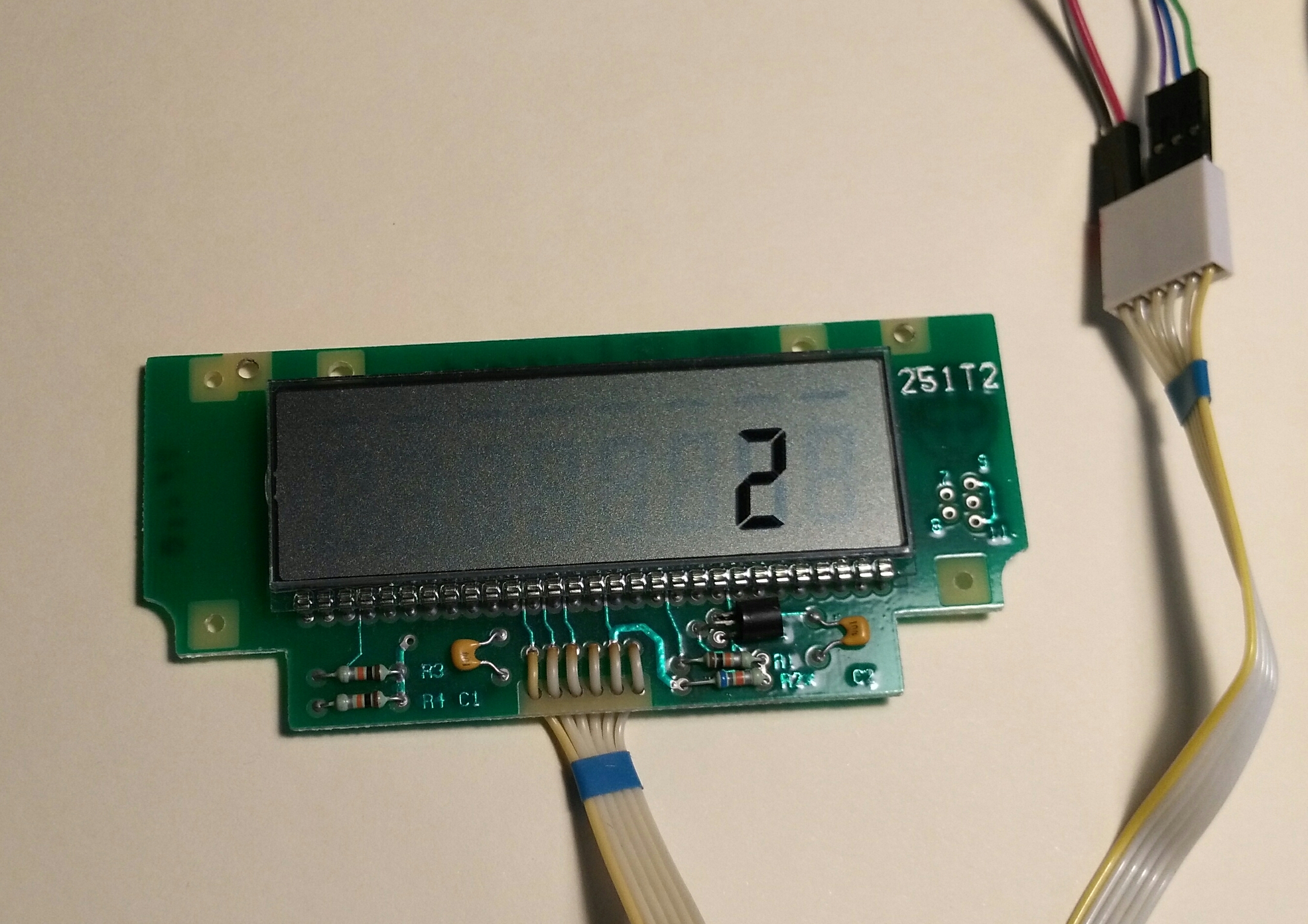
How to connect the display to Arduino? Several inscriptions were found on the LCD display board. 5104219-01, 251 12, 251-T2. The Holtek HT1621B chip is used, the datasheet was downloaded and studied. Unfortunately, the type of LCD used was never identified.
Having called the tester the conclusions (6 conclusions) I determined their purpose:
')
1) Data
2) WR
3) CS
4) unknown *
5) Gnd
6) Vdd (+5 v)
* - connected resistors, capacitors, as I needed, I did not understand deeply.
I used ready-made procedures for working with HT1621 ports from Arduino.
Chip HT1621 128 cells for LCD, which are organized as follows 32x4 bits, in memory it is 16 bytes. In my LCD, the outputs of Com0, Com1, Com2 and all segments 0-31 were connected.
To determine which address and which bit is responsible for which segment a simple program was written that iterates over all addresses and all bits. The results were recorded in a spreadsheet for further analysis. This is how the filled table looks like.
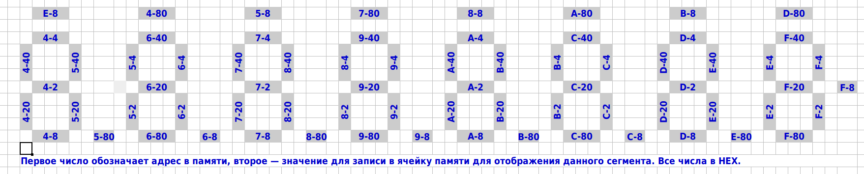
Now it became clear how to control the display. So, for example, to enable segments B and C in the first position (leftmost), you need to change bits D5 and D6 to 1 at address 0x05, the remaining bits should be left unchanged, as they will affect other positions.
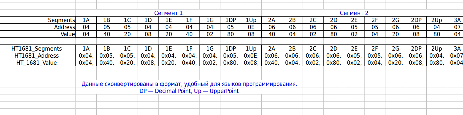
If you look at the table, you can see that in order to display a digit, you need to change several bits in several bytes. I solved this problem as follows. Several tables were prepared:
HT1681_Address (72 bytes), HT_1681_Value (72 bytes), these two tables are related as follows - the second table is a mask (for OR) to set the corresponding bit to 1, with the first nine bytes responsible for segments A, B, C, D , E, F, G + decimal point + or rather the “underscore” of the first familiarity, the next nine - behind the segments of the second familiarity, and so on. The first table is the addresses that correspond to the second table. To understand below is an illustration.
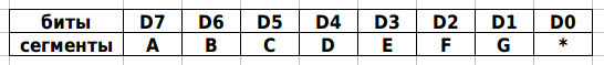
b7SegDsp (10 bytes) This table encodes which segments should be included to display the number. The first byte is the encoding of the number 0, the last byte encodes 9. The older seven bits of D7-D1 encode AG segments, the lower D0 is not used, I set it to 0 besides, it saves one bit-shift operation to the left — I use the 0x80 mask to check the bit.
HT1681_Screen (16 bytes) is just video memory, all 16 bytes. Initially, everything is rendered in memory, and then everything is copied to the HT1621.
Below is the code that renders the HT1681_Screen, which is then simply output to the memory chip for display.
Having examined this good, I became the owner of three LCD displays and three receipt printers.
How to connect the display to Arduino? Several inscriptions were found on the LCD display board. 5104219-01, 251 12, 251-T2. The Holtek HT1621B chip is used, the datasheet was downloaded and studied. Unfortunately, the type of LCD used was never identified.
Having called the tester the conclusions (6 conclusions) I determined their purpose:
')
1) Data
2) WR
3) CS
4) unknown *
5) Gnd
6) Vdd (+5 v)
* - connected resistors, capacitors, as I needed, I did not understand deeply.
I used ready-made procedures for working with HT1621 ports from Arduino.
Chip HT1621 128 cells for LCD, which are organized as follows 32x4 bits, in memory it is 16 bytes. In my LCD, the outputs of Com0, Com1, Com2 and all segments 0-31 were connected.
To determine which address and which bit is responsible for which segment a simple program was written that iterates over all addresses and all bits. The results were recorded in a spreadsheet for further analysis. This is how the filled table looks like.
Now it became clear how to control the display. So, for example, to enable segments B and C in the first position (leftmost), you need to change bits D5 and D6 to 1 at address 0x05, the remaining bits should be left unchanged, as they will affect other positions.
If you look at the table, you can see that in order to display a digit, you need to change several bits in several bytes. I solved this problem as follows. Several tables were prepared:
- HT1681_Address (72 bytes), HT_1681_Value (72 bytes)
- b7SegDsp (10 bytes)
- HT1681_Screen (16 bytes)
HT1681_Address (72 bytes), HT_1681_Value (72 bytes), these two tables are related as follows - the second table is a mask (for OR) to set the corresponding bit to 1, with the first nine bytes responsible for segments A, B, C, D , E, F, G + decimal point + or rather the “underscore” of the first familiarity, the next nine - behind the segments of the second familiarity, and so on. The first table is the addresses that correspond to the second table. To understand below is an illustration.
Code for Arduino
// HT1681_Segments 1A 1B 1C 1D 1E 1F 1G 1DP 1Up ..... 8A 8B 8C 8D 8E 8F 8G 8DP 8Up const byte HT1681_Address[]= { 0x04,0x05,0x05,0x04,0x04,0x04,0x04,0x05,0x0E, 0x06,0x06,0x06,0x06,0x05,0x05,0x06,0x06,0x04, 0x07,0x08,0x08,0x07,0x07,0x07,0x07,0x08,0x05, 0x09,0x09,0x09,0x09,0x08,0x08,0x09,0x09,0x07, 0x0A,0x0B,0x0B,0x0A,0x0A,0x0A,0x0A,0x0B,0x08, 0x0C,0x0C,0x0C,0x0C,0x0B,0x0B,0x0C,0x0C,0x0A, 0x0D,0x0E,0x0E,0x0D,0x0D,0x0D,0x0D,0x0E,0x0B, 0x0F,0x0F,0x0F,0x0F,0x0E,0x0E,0x0F,0x0F,0x0D }; const byte HT_1681_Value[]= { 0x04,0x40,0x20,0x08,0x20,0x40,0x02,0x80,0x08, 0x40,0x04,0x02,0x80,0x02,0x04,0x20,0x08,0x80, 0x04,0x40,0x20,0x08,0x20,0x40,0x02,0x80,0x08, 0x40,0x04,0x02,0x80,0x02,0x04,0x20,0x08,0x80, 0x04,0x40,0x20,0x08,0x20,0x40,0x02,0x80,0x08, 0x40,0x04,0x02,0x80,0x02,0x04,0x20,0x08,0x80, 0x04,0x40,0x20,0x08,0x20,0x40,0x02,0x80,0x08, 0x40,0x04,0x02,0x80,0x02,0x04,0x20,0x08,0x80 }; b7SegDsp (10 bytes) This table encodes which segments should be included to display the number. The first byte is the encoding of the number 0, the last byte encodes 9. The older seven bits of D7-D1 encode AG segments, the lower D0 is not used, I set it to 0 besides, it saves one bit-shift operation to the left — I use the 0x80 mask to check the bit.
HT1681_Screen (16 bytes) is just video memory, all 16 bytes. Initially, everything is rendered in memory, and then everything is copied to the HT1621.
Below is the code that renders the HT1681_Screen, which is then simply output to the memory chip for display.
// 0<=bPos<=7 - bNum. // - lDecimalPoint=1 // "" - lUpperLine=1 void HT1681_Display(byte bPos, byte bNum, byte lDecimalPoint, byte lUpperLine) { byte i, bCheckByte, bAddr, bValue; bCheckByte=b7SegDsp[bNum]; // - for(i=bPos*9;i<=bPos*9+6;i++) // 7 { if ( (bCheckByte & 0x80) == 0x80) // =1 { bAddr=HT1681_Address[i]; // bValue=HT_1681_Value[i]; // HT1681_Screen[bAddr] = (HT1681_Screen[bAddr] | bValue); // OR 1 }; bCheckByte=bCheckByte << 0x01; // } if (lDecimalPoint==1) // { bAddr = HT1681_Address[(bPos*9)+7]; bValue = HT_1681_Value[(bPos*9)+7]; HT1681_Screen[bAddr] = (HT1681_Screen[bAddr] | bValue); }; if (lUpperLine==1) // { bAddr = HT1681_Address[(bPos*9)+8]; bValue = HT_1681_Value[(bPos*9)+8]; HT1681_Screen[bAddr] = (HT1681_Screen[bAddr] | bValue); }; } Under the spoiler all the code is laid out for the Arduino
// http://arduino.ru/forum/programmirovanie/ht1621 // http://arduino.ru/forum/programmirovanie/ht1621#comment-76371 #define sbi(x, y) (x |= (1 << y)) /*set Register x of y*/ #define cbi(x, y) (x &= ~(1 <<y )) /*Clear Register x of y*/ #define uchar unsigned char #define uint unsigned int //Defined HT1621's command #define ComMode 0x48 //4COM,1/2bias 1000 010 1001 0 #define RCosc 0x30 //on-chip RC oscillator(Power-on default)1000 0011 0000 #define LCD_on 0x06 //Turn on LCD #define LCD_off 0x04 //Turn off LCD #define Sys_en 0x02 //Turn on system oscillator 1000 0000 0010 #define CTRl_cmd 0x80 //Write control cmd #define Data_cmd 0xa0 //Write data cmd // //Define port HT1621 data port #define CS 2 //Pin 2 as chip selection output #define WR 3 //Pin 3 as read clock output #define DATA 4 //Pin 4 as Serial data output #define CS1 digitalWrite(CS, HIGH) #define CS0 digitalWrite(CS, LOW) #define WR1 digitalWrite(WR, HIGH) #define WR0 digitalWrite(WR, LOW) #define DATA1 digitalWrite(DATA, HIGH) #define DATA0 digitalWrite(DATA, LOW) #define DelayTime 1000 byte bMask; // HT1681_Segments 1A 1B 1C 1D 1E 1F 1G 1DP 1Up ..... 8A 8B 8C 8D 8E 8F 8G 8DP 8Up const byte HT1681_Address[]= { 0x04,0x05,0x05,0x04,0x04,0x04,0x04,0x05,0x0E, 0x06,0x06,0x06,0x06,0x05,0x05,0x06,0x06,0x04, 0x07,0x08,0x08,0x07,0x07,0x07,0x07,0x08,0x05, 0x09,0x09,0x09,0x09,0x08,0x08,0x09,0x09,0x07, 0x0A,0x0B,0x0B,0x0A,0x0A,0x0A,0x0A,0x0B,0x08, 0x0C,0x0C,0x0C,0x0C,0x0B,0x0B,0x0C,0x0C,0x0A, 0x0D,0x0E,0x0E,0x0D,0x0D,0x0D,0x0D,0x0E,0x0B, 0x0F,0x0F,0x0F,0x0F,0x0E,0x0E,0x0F,0x0F,0x0D }; const byte HT_1681_Value[]= { 0x04,0x40,0x20,0x08,0x20,0x40,0x02,0x80,0x08, 0x40,0x04,0x02,0x80,0x02,0x04,0x20,0x08,0x80, 0x04,0x40,0x20,0x08,0x20,0x40,0x02,0x80,0x08, 0x40,0x04,0x02,0x80,0x02,0x04,0x20,0x08,0x80, 0x04,0x40,0x20,0x08,0x20,0x40,0x02,0x80,0x08, 0x40,0x04,0x02,0x80,0x02,0x04,0x20,0x08,0x80, 0x04,0x40,0x20,0x08,0x20,0x40,0x02,0x80,0x08, 0x40,0x04,0x02,0x80,0x02,0x04,0x20,0x08,0x80 }; // 0-9 7Segment Display Description // D7 D6 D5 D4 D3 D2 D1 D0 // ABCDEFG * // const byte b7SegDsp[]= { 0xFC,0x60,0xDA,0xF2,0x66,0xB6,0xBE,0xE0,0xFE,0xE6 }; // virtual screen 12x6 bits = 72 bits (000X000X) byte HT1681_Screen[]= { 0x00,0x00,0x00,0x00,0x00,0x00,0x00,0x00,0x00,0x00,0x00,0x00,0x00,0x00,0x00,0x00 }; // ********************************************************************************************************************************* void SendBit_1621(uchar sdata,uchar cnt) //High bit first { uchar i; for(i=0;i<cnt;i++) { WR0; delayMicroseconds(1); if(sdata&0x80) DATA1; else DATA0; delayMicroseconds(1); WR1; delayMicroseconds(1); sdata<<=1; } delayMicroseconds(1); } void Init_1621(void) { SendCmd_1621(Sys_en); SendCmd_1621(RCosc); SendCmd_1621(ComMode); SendCmd_1621(LCD_on); } void SendCmd_1621(uchar command) { CS0; SendBit_1621(0x80,4); SendBit_1621(command,8); CS1; } void Write_1621(uchar addr,uchar sdata) { addr<<=3; CS0; SendBit_1621(0xa0,3); //Write MODE“101” SendBit_1621(addr,6); //Write addr high 6 bits SendBit_1621(sdata,8); //Write data 8 bits CS1; } void LCDoff(void) { SendCmd_1621(LCD_off); } void LCDon(void) { SendCmd_1621(LCD_on); } void HT1681_Clear(void) { byte bAddress=0x00; for(byte j=0;j<=0x0F;j++) { bAddress=j; HT1681_Screen[bAddress]=0x00; }; }; void HT1681_Show(void) { byte i; for(i=0;i<=0x0F;i++) { Write_1621(i, HT1681_Screen[i]); }; } // 0<=bPos<=7 - bNum. // - lDecimalPoint=1 // "" - lUpperLine=1 void HT1681_Display(byte bPos, byte bNum, byte lDecimalPoint, byte lUpperLine) { byte i, bCheckByte, bAddr, bValue; bCheckByte=b7SegDsp[bNum]; // - for(i=bPos*9;i<=bPos*9+6;i++) // 7 { if ( (bCheckByte & 0x80) == 0x80) // =1 { bAddr=HT1681_Address[i]; // bValue=HT_1681_Value[i]; // HT1681_Screen[bAddr] = (HT1681_Screen[bAddr] | bValue); // OR 1 }; bCheckByte=bCheckByte << 0x01; // } if (lDecimalPoint==1) // { bAddr = HT1681_Address[(bPos*9)+7]; bValue = HT_1681_Value[(bPos*9)+7]; HT1681_Screen[bAddr] = (HT1681_Screen[bAddr] | bValue); }; if (lUpperLine==1) // { bAddr = HT1681_Address[(bPos*9)+8]; bValue = HT_1681_Value[(bPos*9)+8]; HT1681_Screen[bAddr] = (HT1681_Screen[bAddr] | bValue); }; } // *************************************************************************************************************************** void setup() { pinMode(CS, OUTPUT); //Pin 2 pinMode(WR, OUTPUT); //Pin 3 pinMode(DATA, OUTPUT); //Pin 4 Init_1621(); HT1681_Clear(); HT1681_Show(); Serial.begin(9600); } // *************************************************************************************************************************** void loop() { byte i,j; HT1681_Clear(); HT1681_Show(); LCDoff(); delay(100); for (i=0; i<=7; i++) { for (j=0; j<=9; j++) { HT1681_Clear(); LCDoff(); HT1681_Display(i,j,0,0); HT1681_Show(); LCDon(); delay(150); }; }; } Video of the program
Source: https://habr.com/ru/post/374199/
All Articles