Noolite + Arbor - make a convenient light at the cottage
Today I would like to tell you about one case in which it was very good to use radio switches - Control of the light on the cottage terrace .
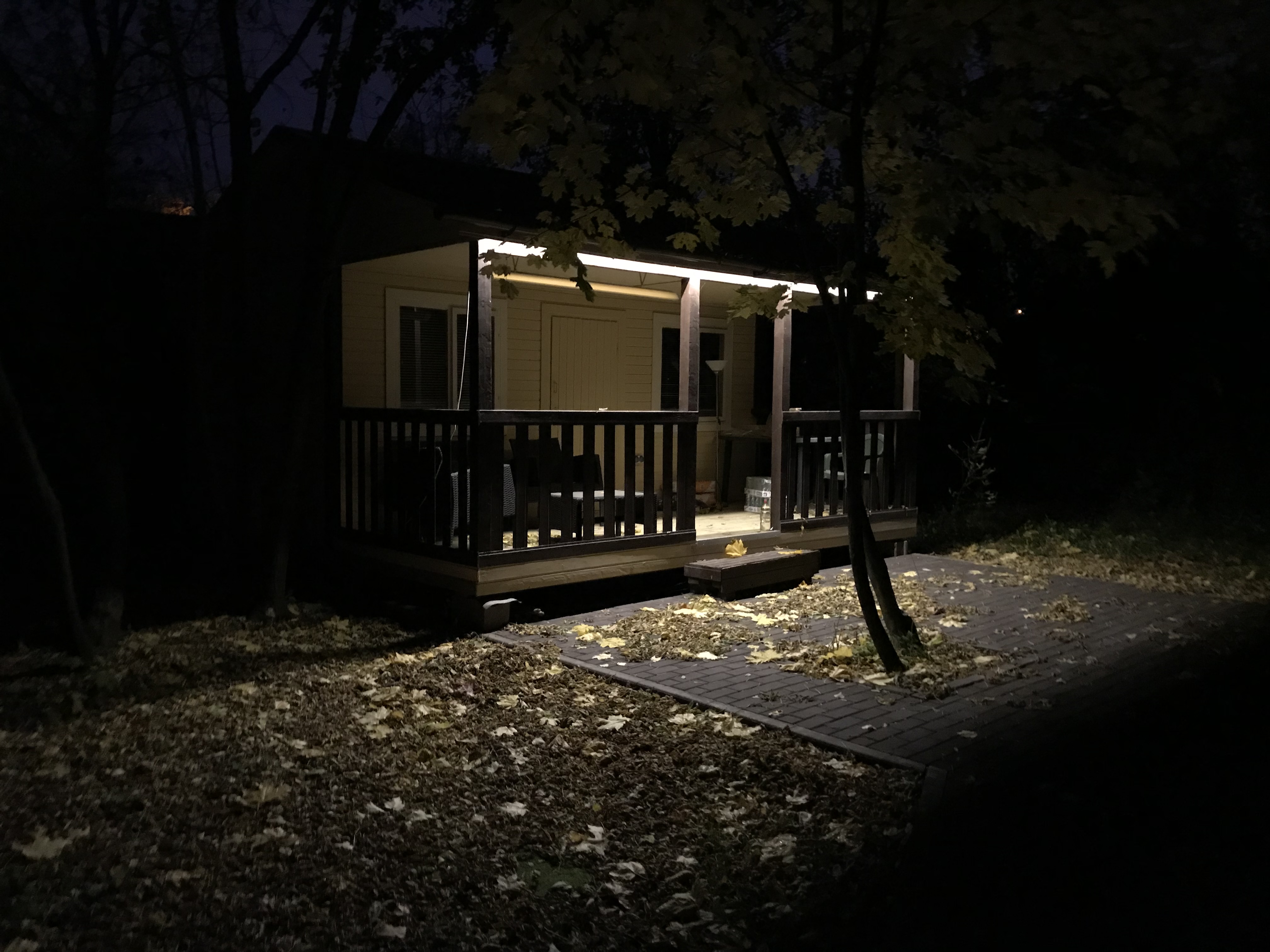
Many owners of dachas have a veranda on which absorption and sometimes barbecues are prepared in summertime. But when night falls, a problem arises - when walking between the House <-> Veranda, difficulties arise due to the lack of light, and until the switch is found we have to do a lot to touch or use a flashlight on the phone. It is much more convenient to turn on the light from the house (and turn it off when leaving too). To solve this problem, I decided to use Noolite.
At the same time, I checked how far the switches work - in my case there are two concrete walls and 50 meters between the switch and the relay.
(In addition, 1 switch and relay installed on the street, in the spring you can say about survivability after frost)
')
Baseline: Conventional wiring (already existing) with a light switch (mounted).

Light source - LED tape with hidden wiring through the attic.
In preparing the installation, I began to consider various options. It was possible to install a switch + relay but, then 0 would always be active on the transformer that powers the LEDs. In my opinion, this is a bad option, so I decided:
- Dismantle old switch
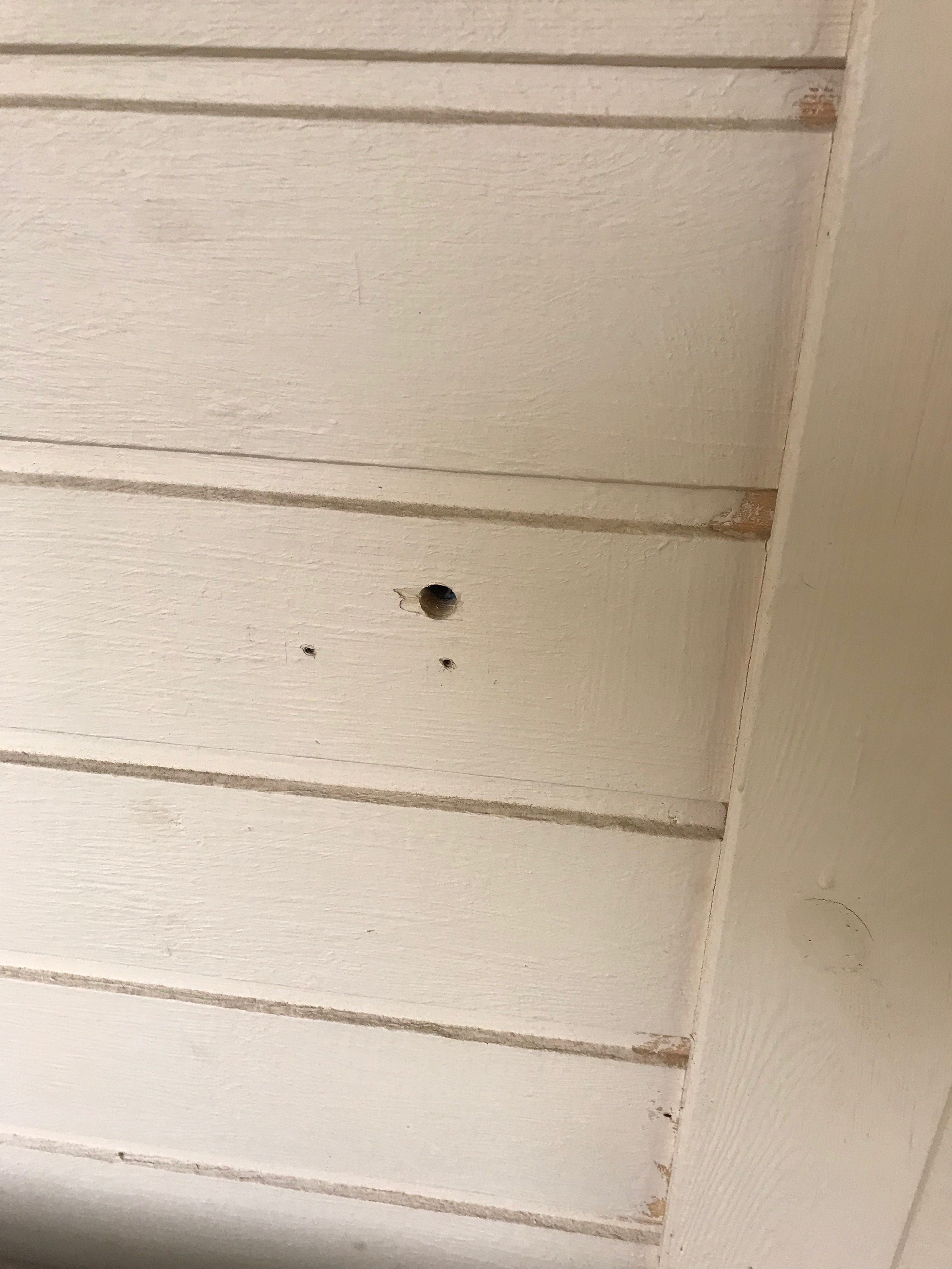
- Close the wires in place of the switch forever
- Install a relay in the open circuit between the transformer and the power plate (on the roof)
- In place of the old switch to install the radio switch
- Mount the second radio switch inside the house
The only thing I was worried about during the preparation was whether the radio channel could break through the iron roof, 50 meters of air and a couple of concrete walls ...
Kit
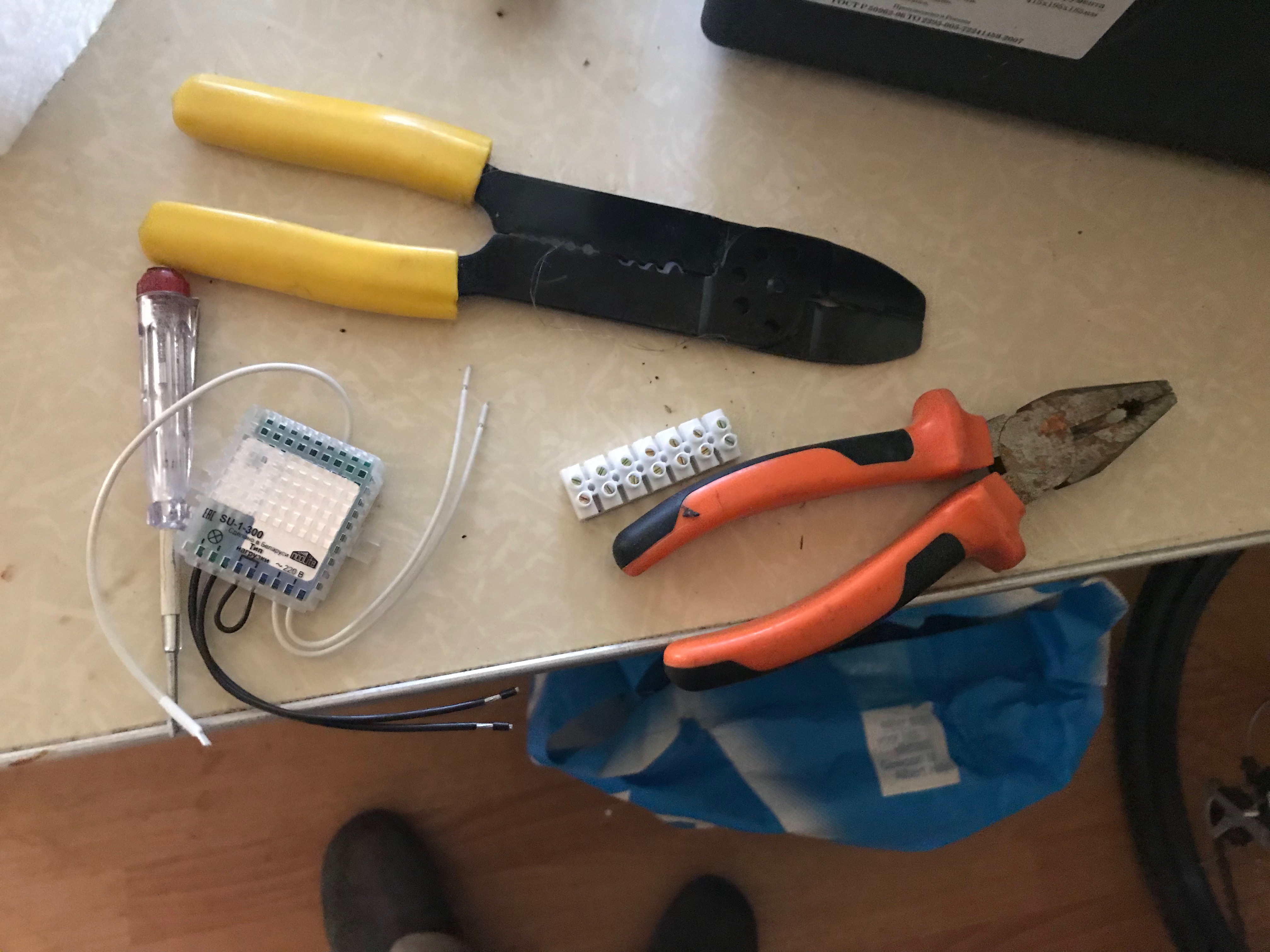
To install, I chose the following kit:
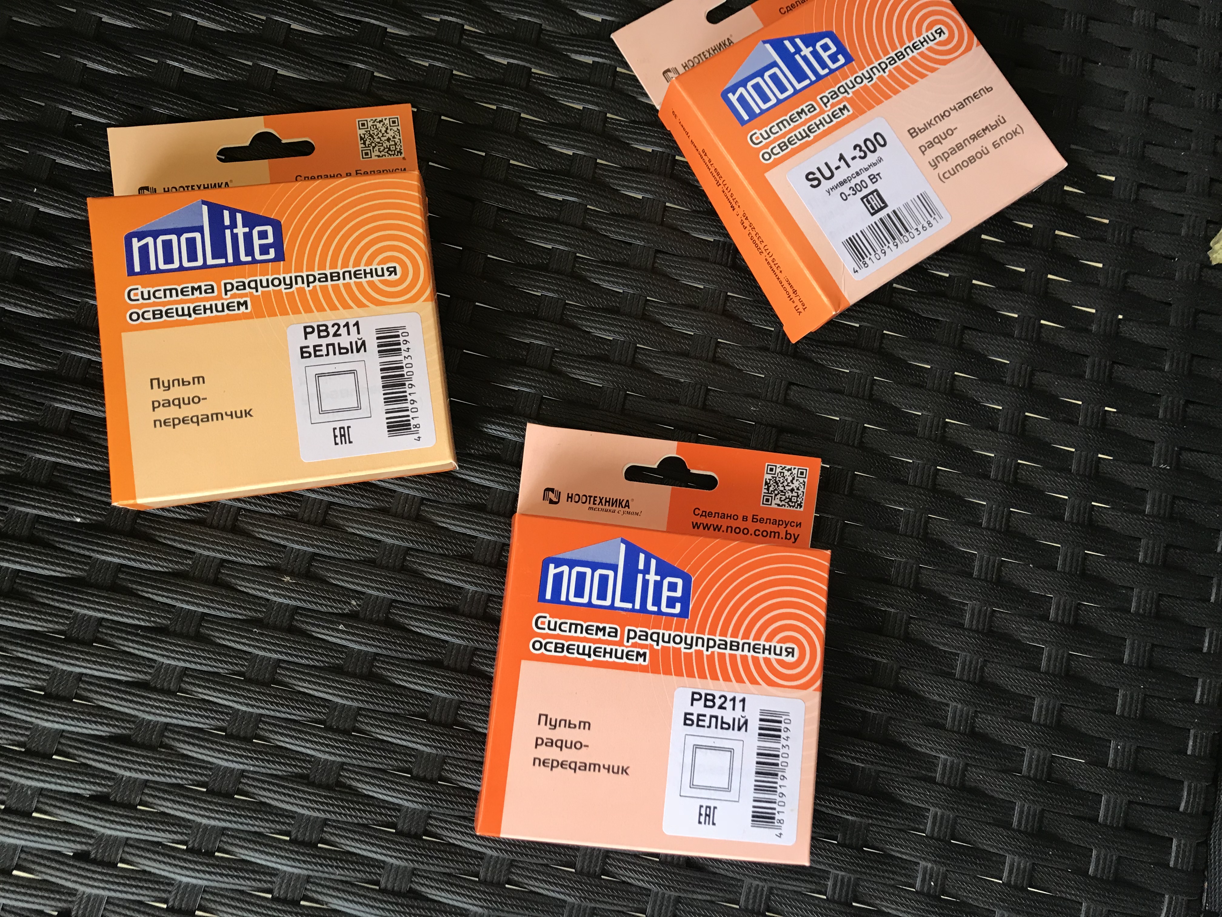
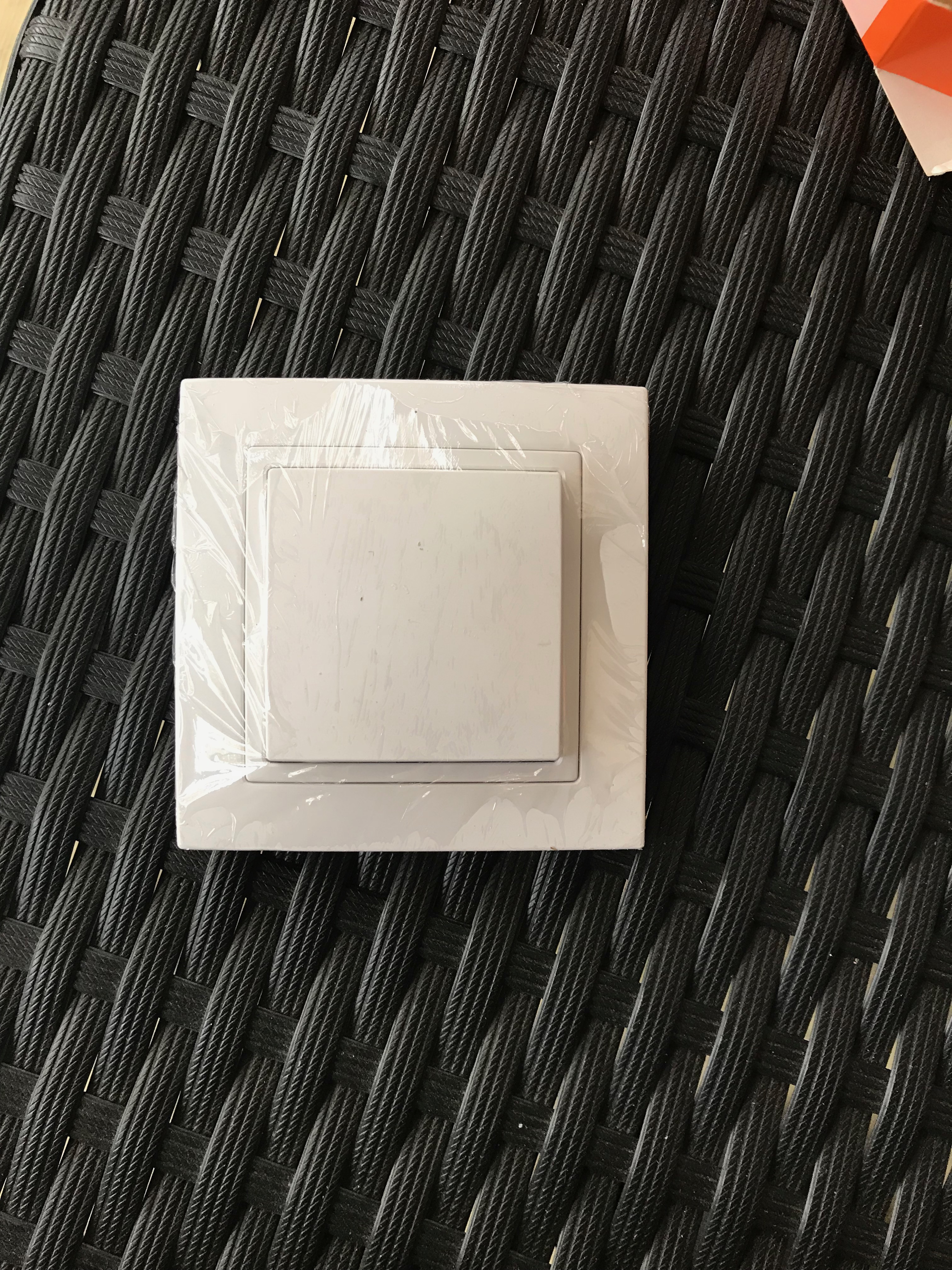
The switches are completely standard - white, by the way, noolite has touch switches, but I did not decide to take them - in my opinion tactile feedback is very important.
The power relay is 300W (if I also connect the LED strip, I advise you to watch how much the transformer consumes at the peak and take the corresponding relay), my transformer is standard from lirouamerlen and consumes at the peak just 300W (but the length of the tape is not as high as possible for him, therefore, construction consumes less)
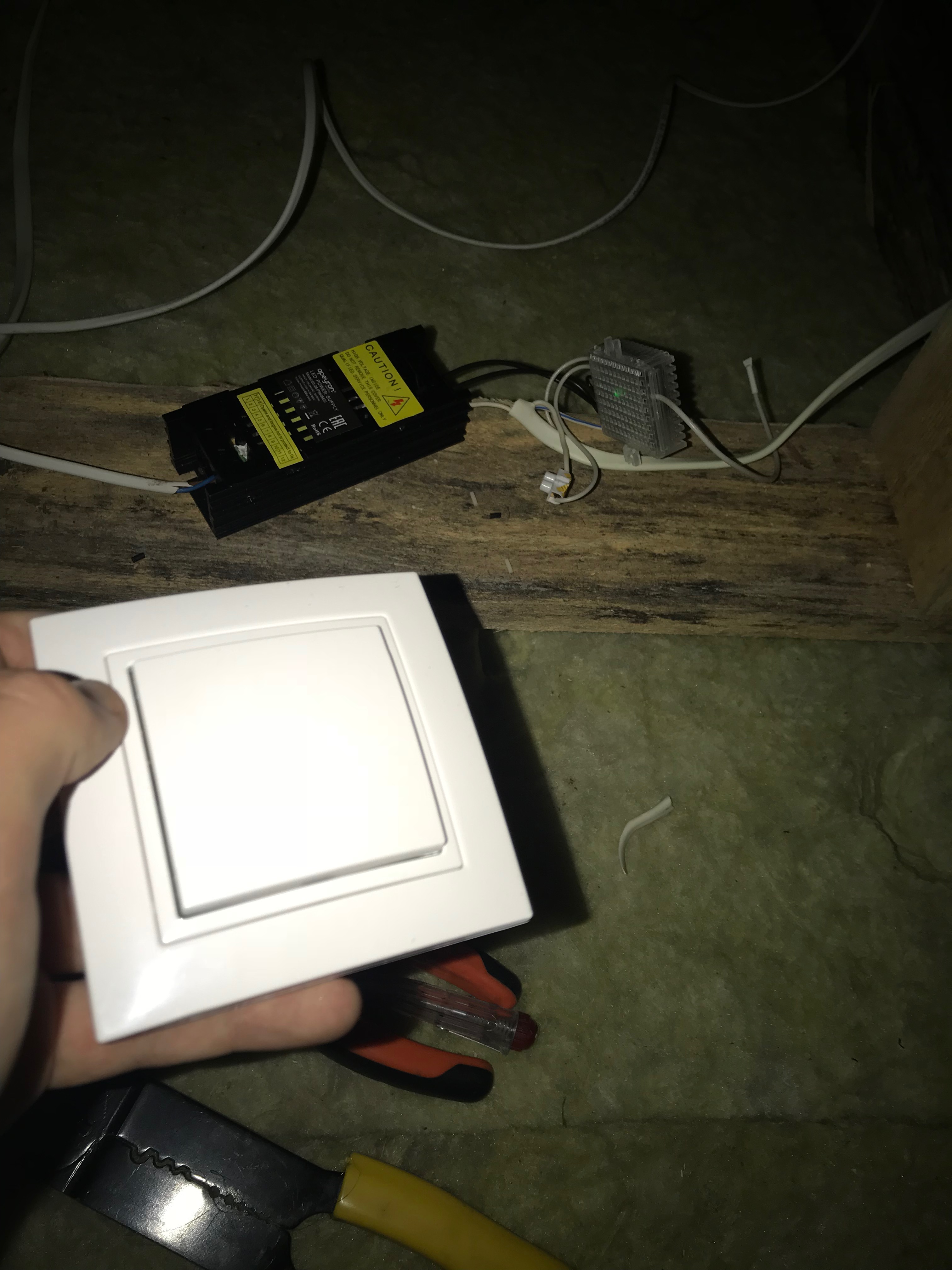
Power relay closer:
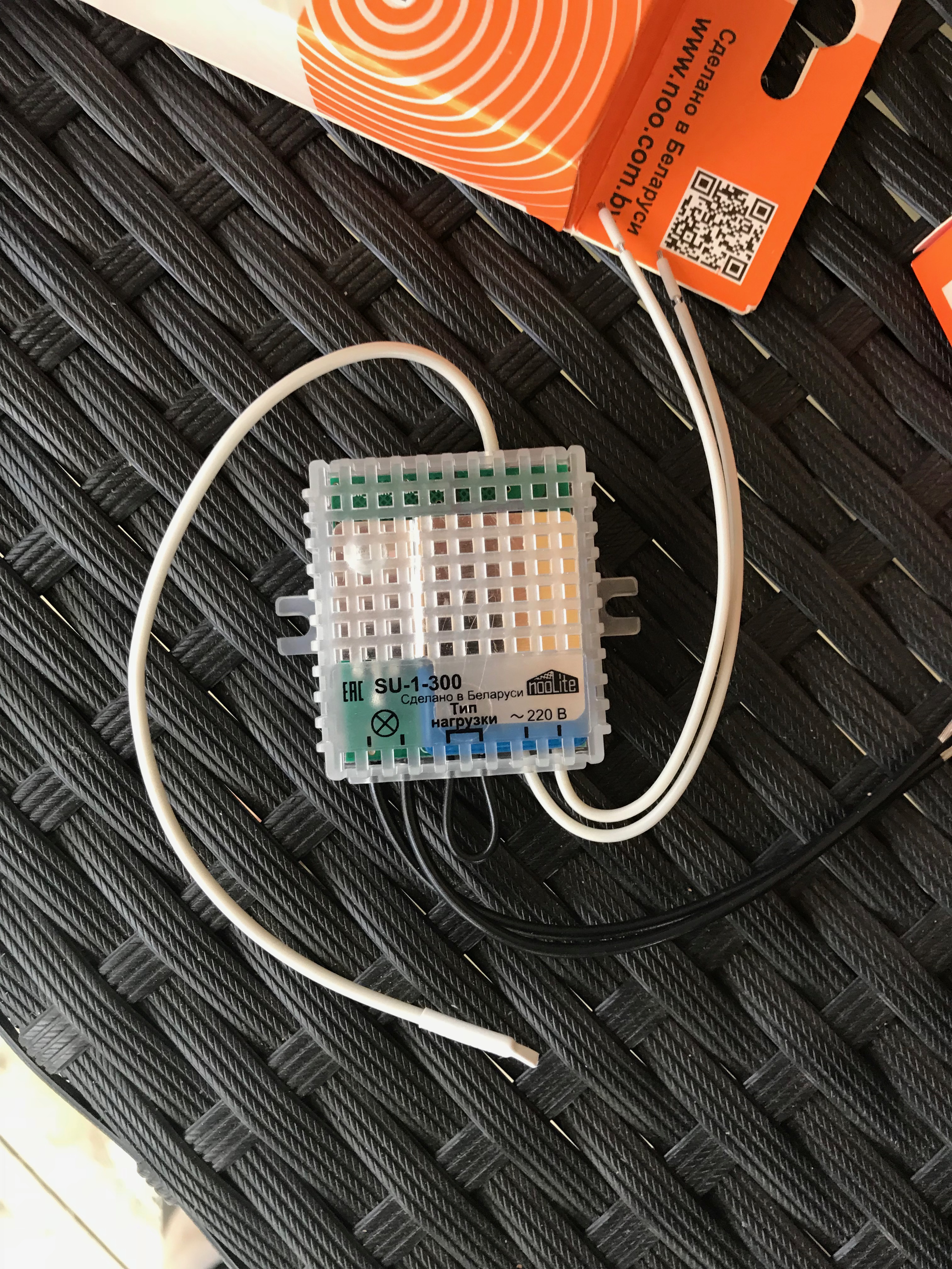
Consists of:
- Two wires - Phase and Zero input
- Two more - Phase and zero to the output (very sorry, but where the output phase and zero - we do not sign)
- The “type of load” jumper - if we plan to dim the light - we need to eat it, if we do not plan (like me) - do not touch
- Antenna
I have already considered the switches earlier, but just in case, we will make sure that nothing has changed:
Installation
All that I (and you) need is for me:
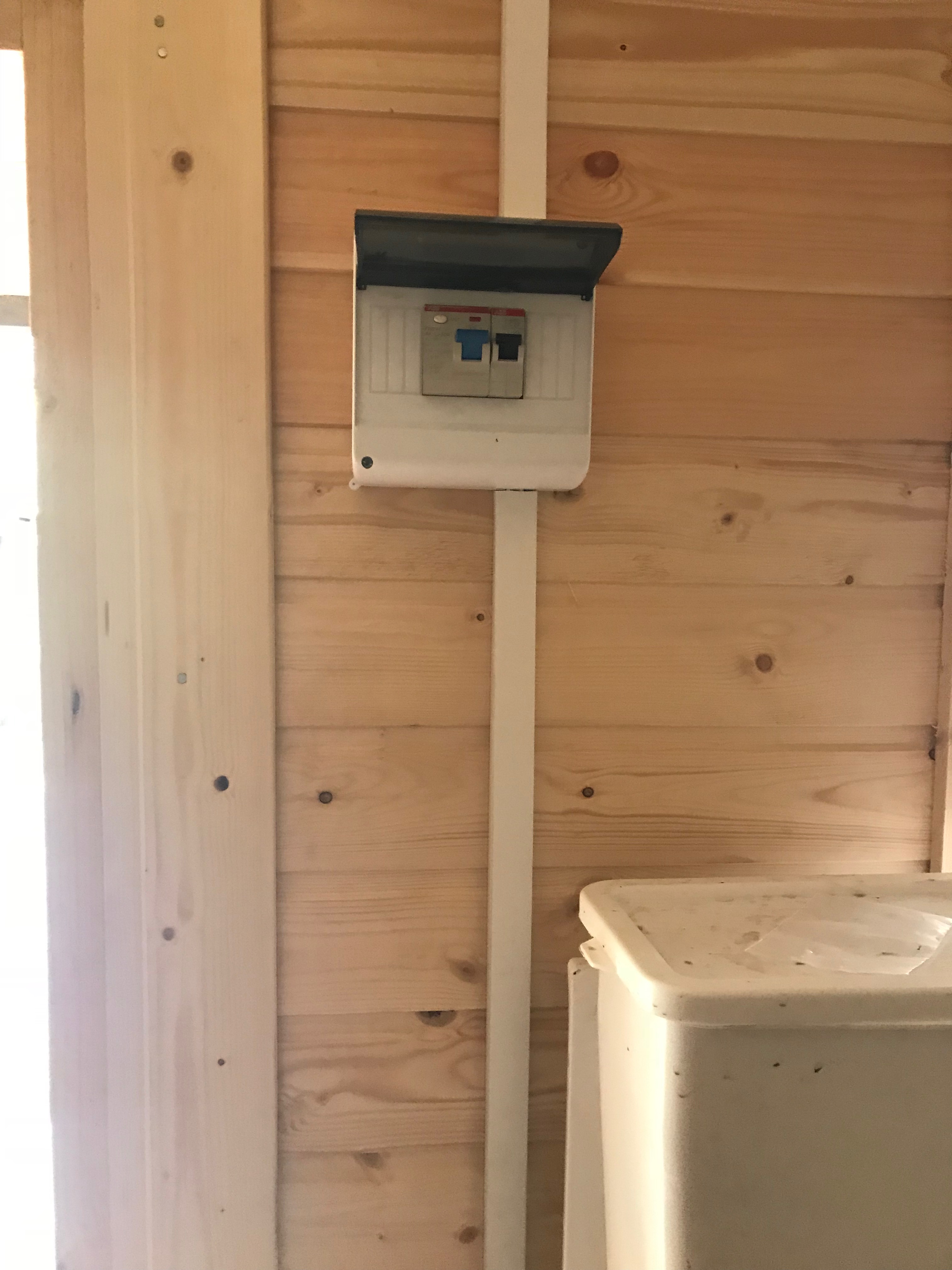
Turn off the voltage
Dismantling switch
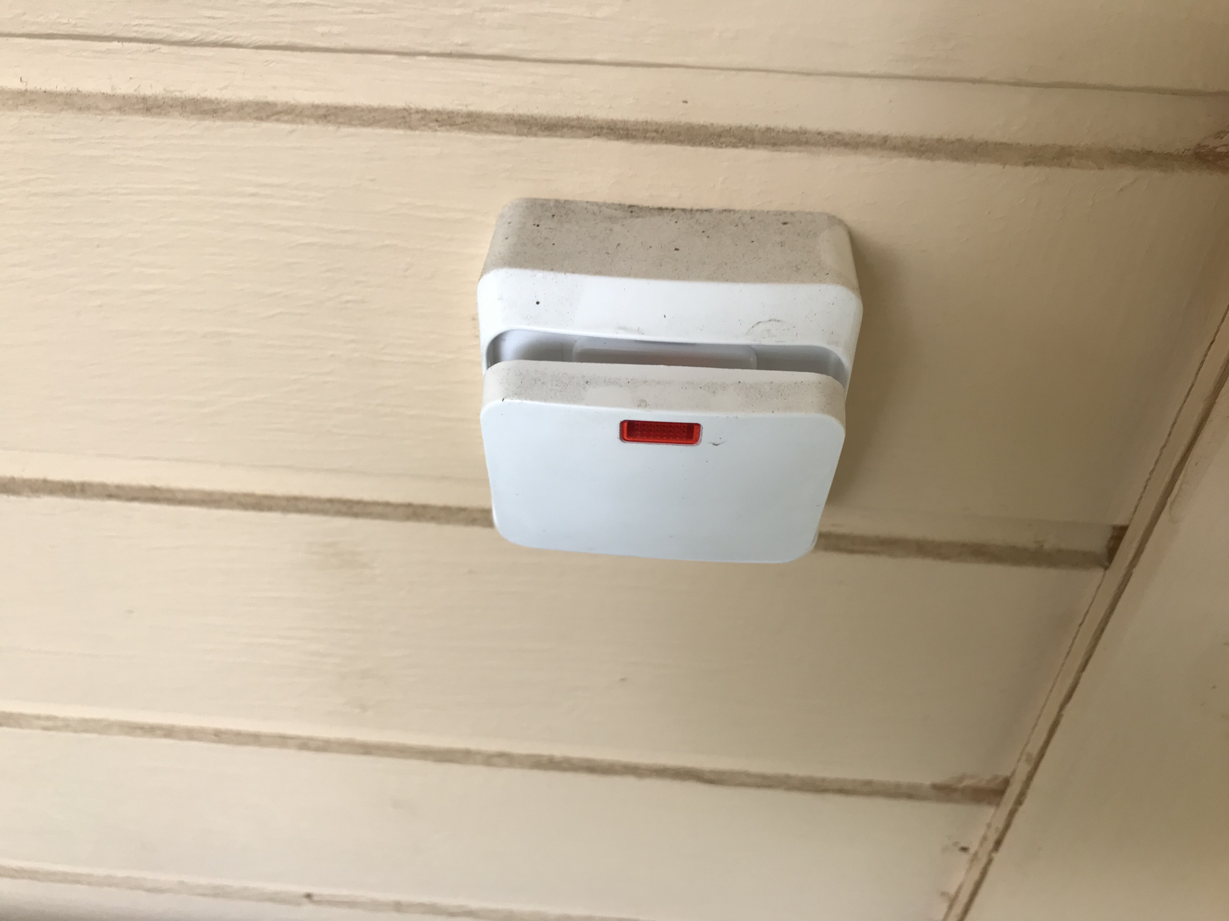
The old switch I have is the most common of lilyuya, with light when the load is turned off, you need to disassemble it as follows ...
We hook the cover with a knife or screwdriver:
Wring out the "legs" with a screwdriver:
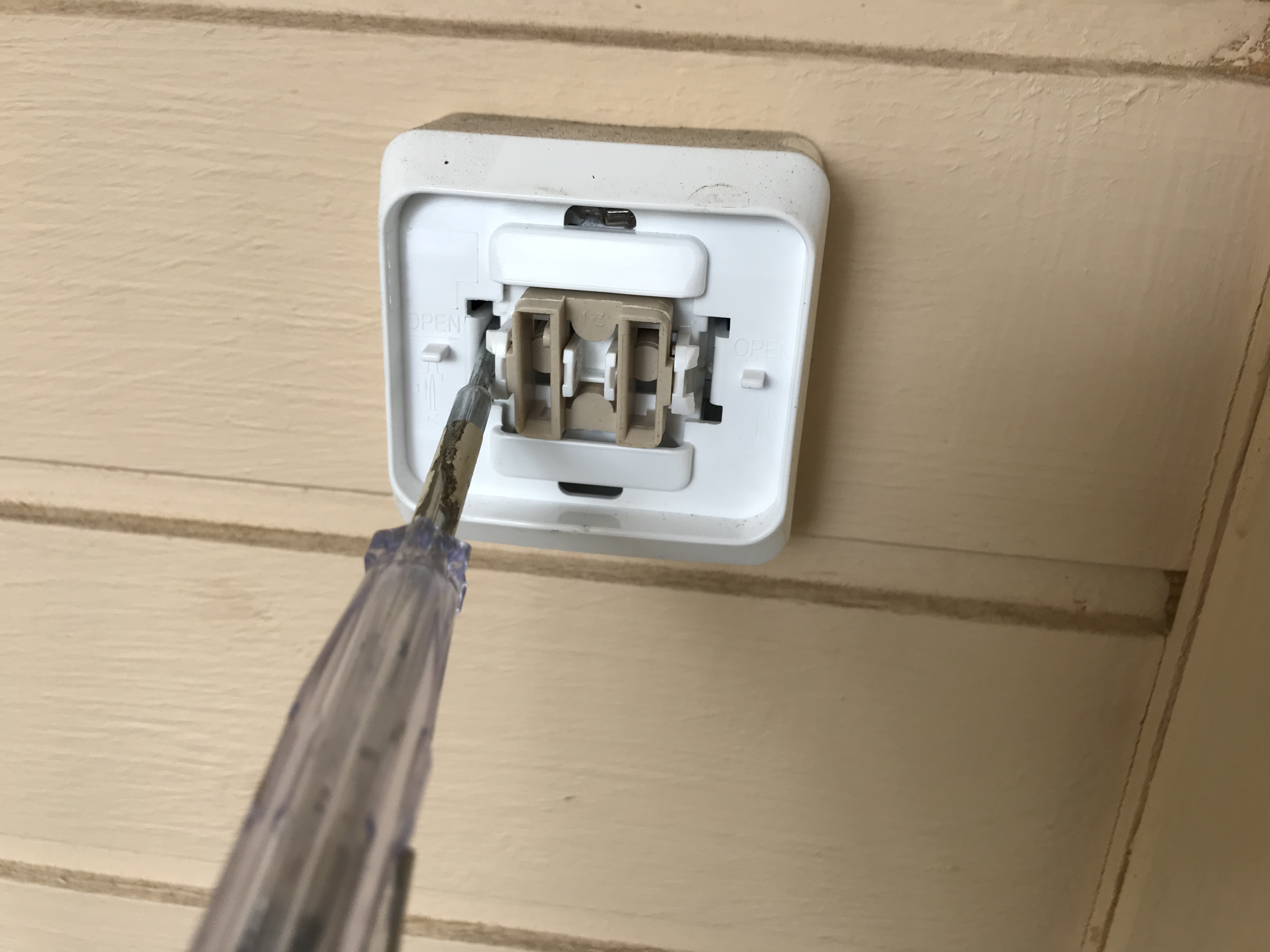
Remove the cover and see the following picture:
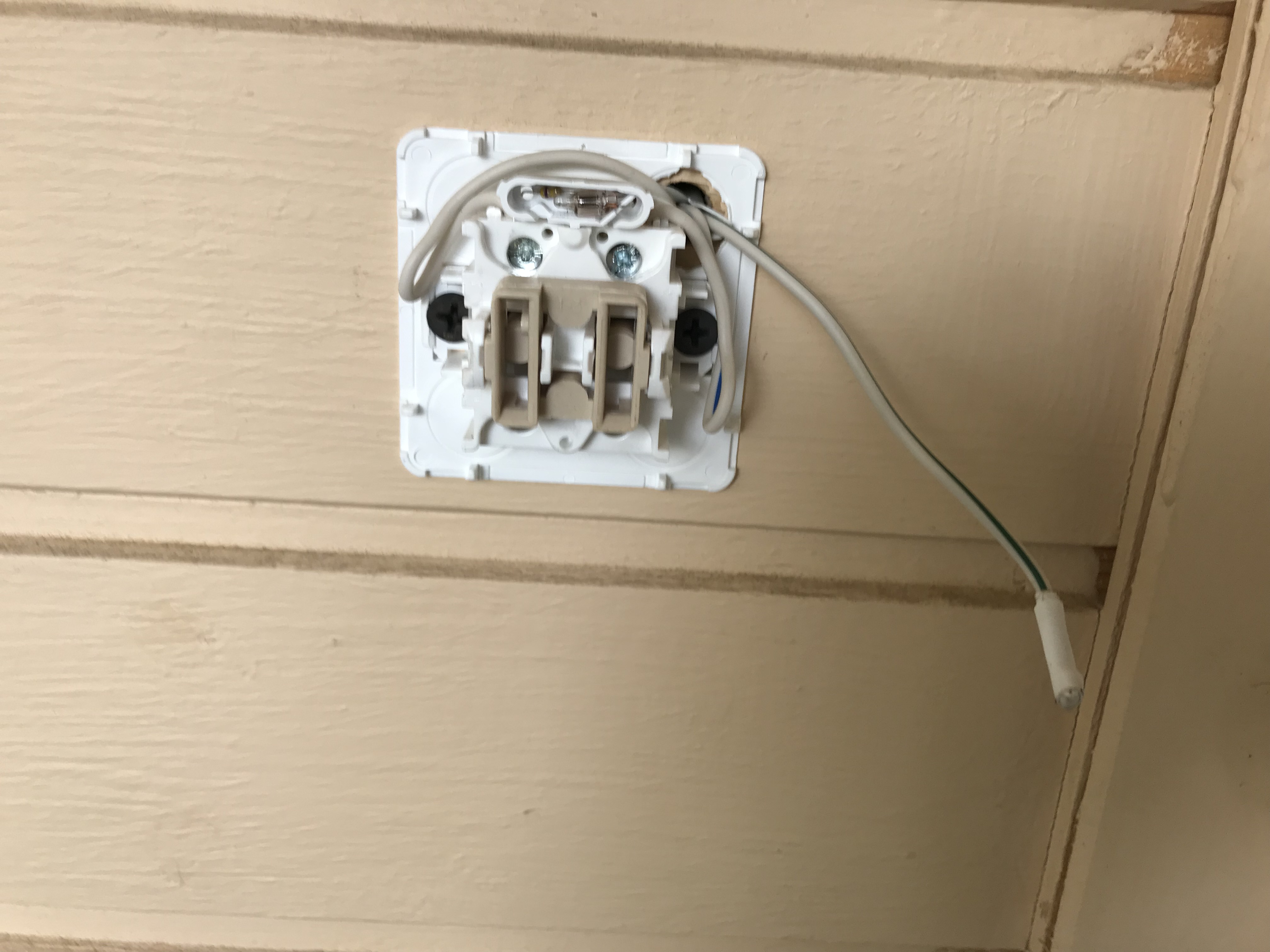
Now unscrew the terminal blocks with current and two screws that hold it on the wall.
After that, I had a rather interesting question - earlier the wiring went to the switch, and now it is not needed there, but the connection of the two wires should not be left in the old place - the new switch is narrow and does not have a place, I decided to pull the wires to the other side, the place of the former switch looks like this:
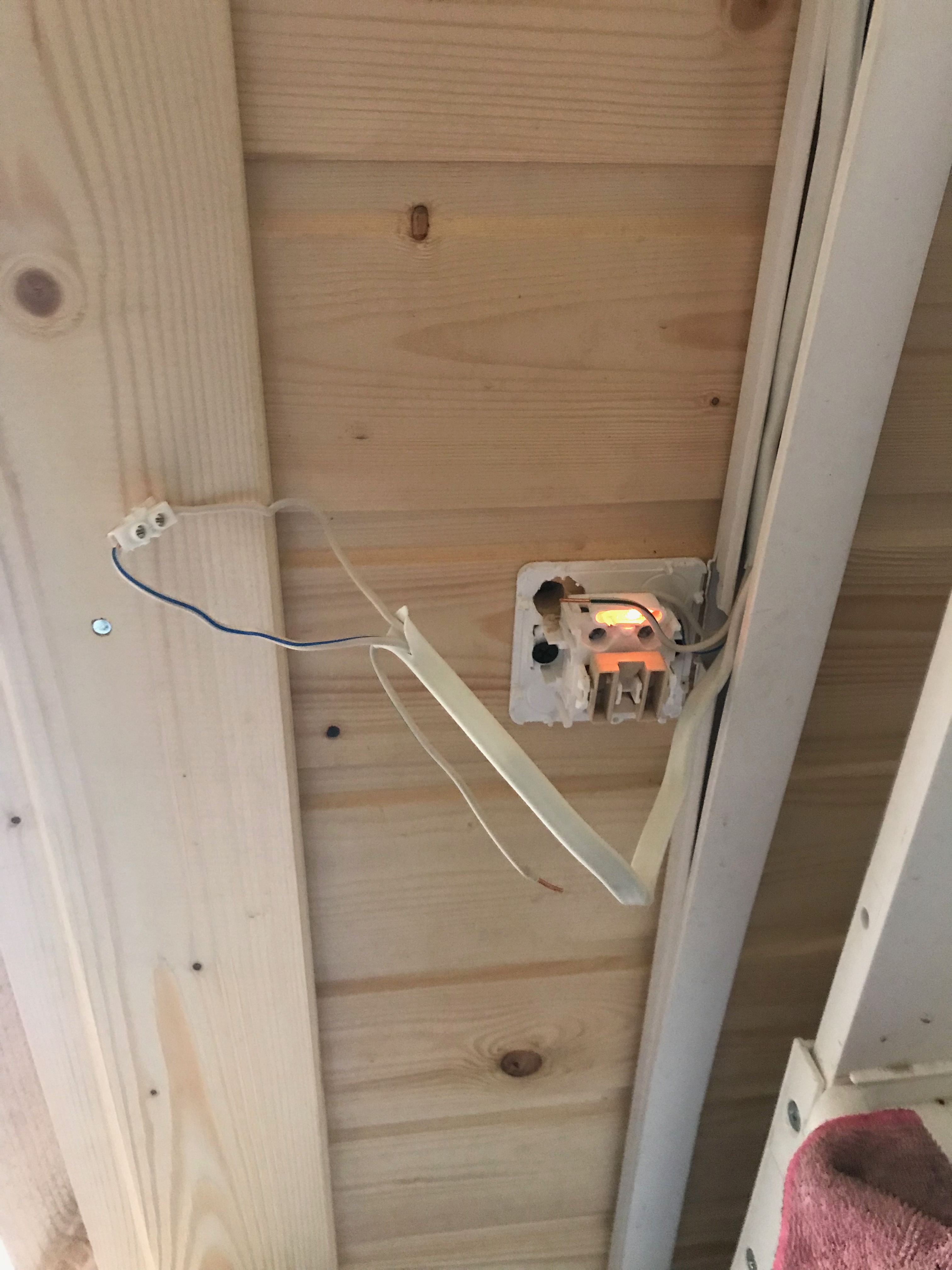
On the other hand, I made the following diagram - to hide the wires, the wiring to the street switch went through the internal one, because of this I had to disassemble it:
The photo also shows connected wires, instead of a switch.
Now the most important part is connecting the relay:
For this, I needed to climb into the attic. This is what the “old” connection looks like: a black block - a transformer 220 - 12v
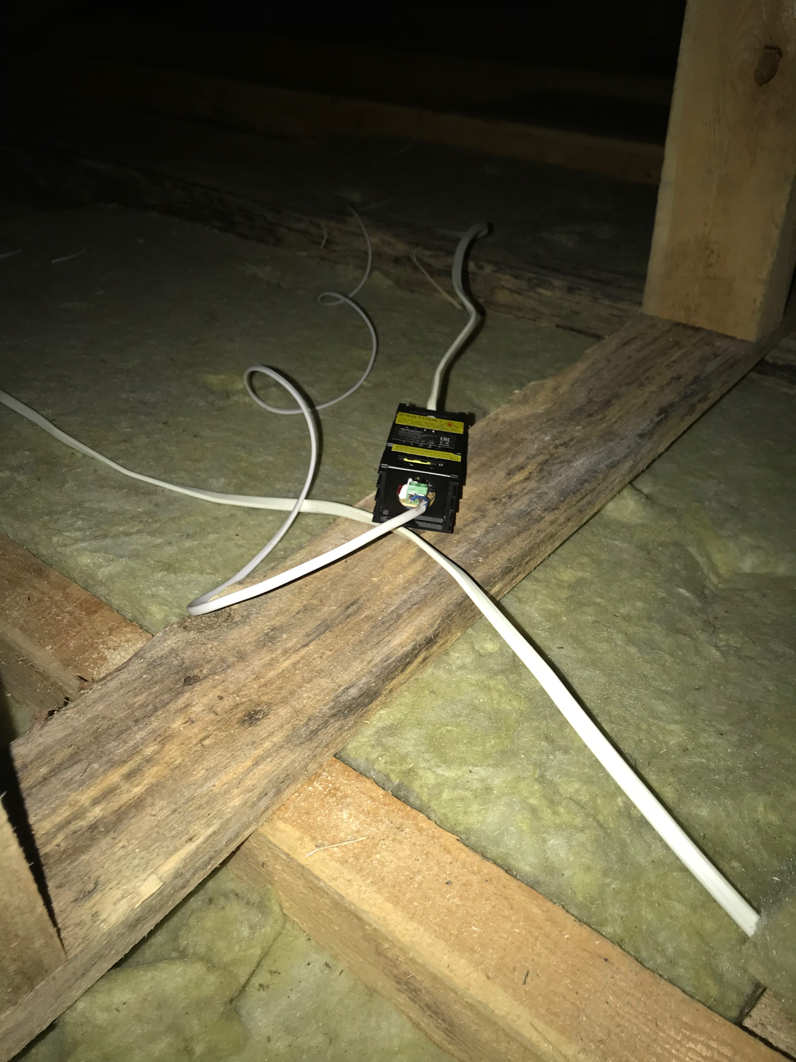
To connect, do the following:
- The incoming power wires of the transformer must be connected to the wires with the inscription 220 in the relay
- Load (transformer) must be connected to the output wires from the relay (X)
After connecting the structure takes the following form:
It remains only to make the conjugation of devices and fix the switches.
Conjugation
It's all quite simple - press the button on the relay itself (roughly speaking, squeezing the bottom of the two sides, the button inside under the plastic - you won't miss) then press the button on the back of the console and press the light button. Then again to the back button of the console and once again to turn on - the light will flash quickly - the conjugation is made.
What is beautiful - the second console can be tied without already entering the hard-to-reach places (in my case - the attic), you can initiate the binding of the second console through the first one.
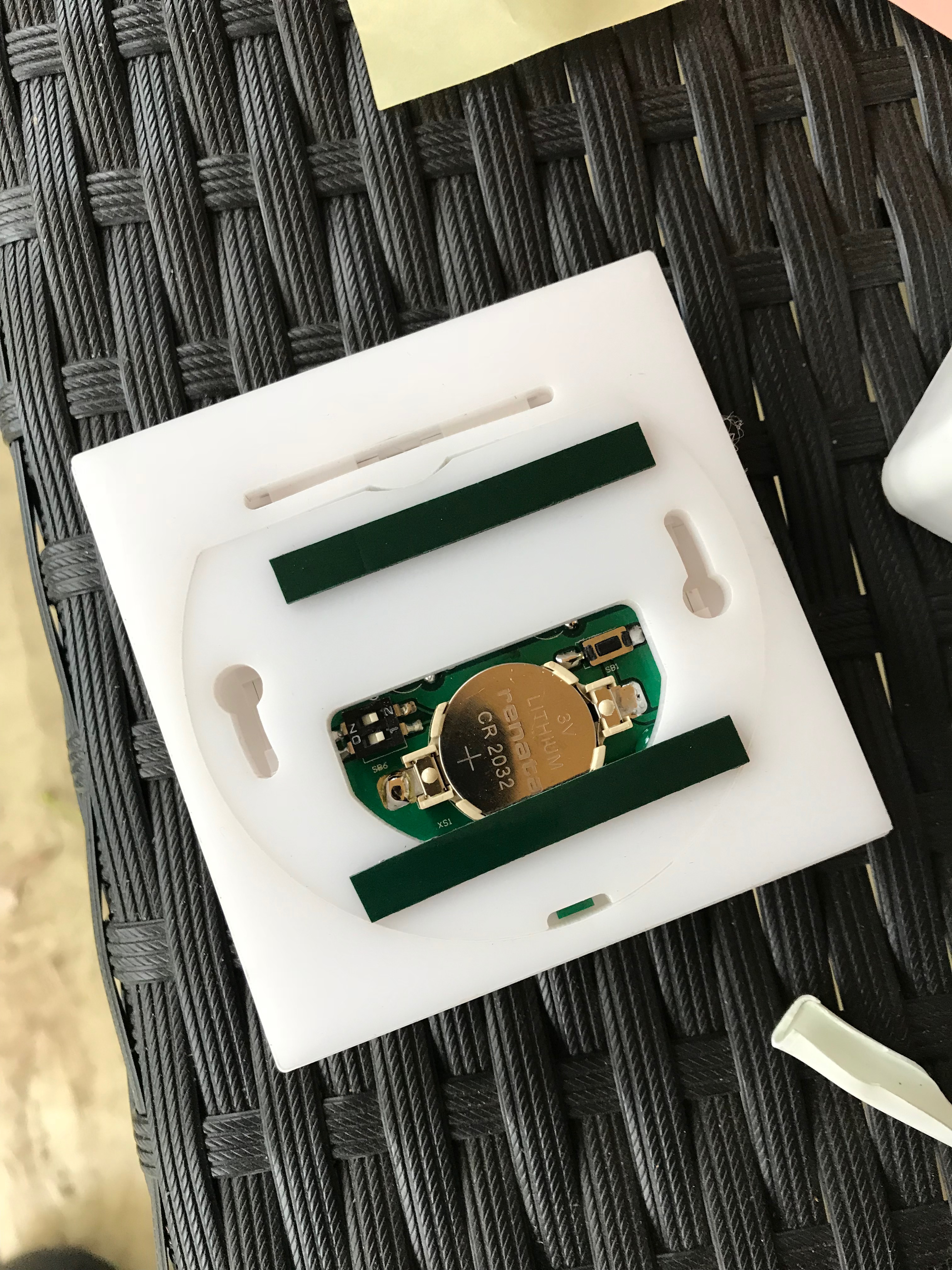
Conjugation button - to the right of the battery.
Well, now it remains to install radio consoles, it would seem - this is the easiest moment, but no!
I do not know what these beautiful black strips of double-sided tape are made of, but I tore off the protective coating from them for about 10 minutes, I would very much like this to be easier.
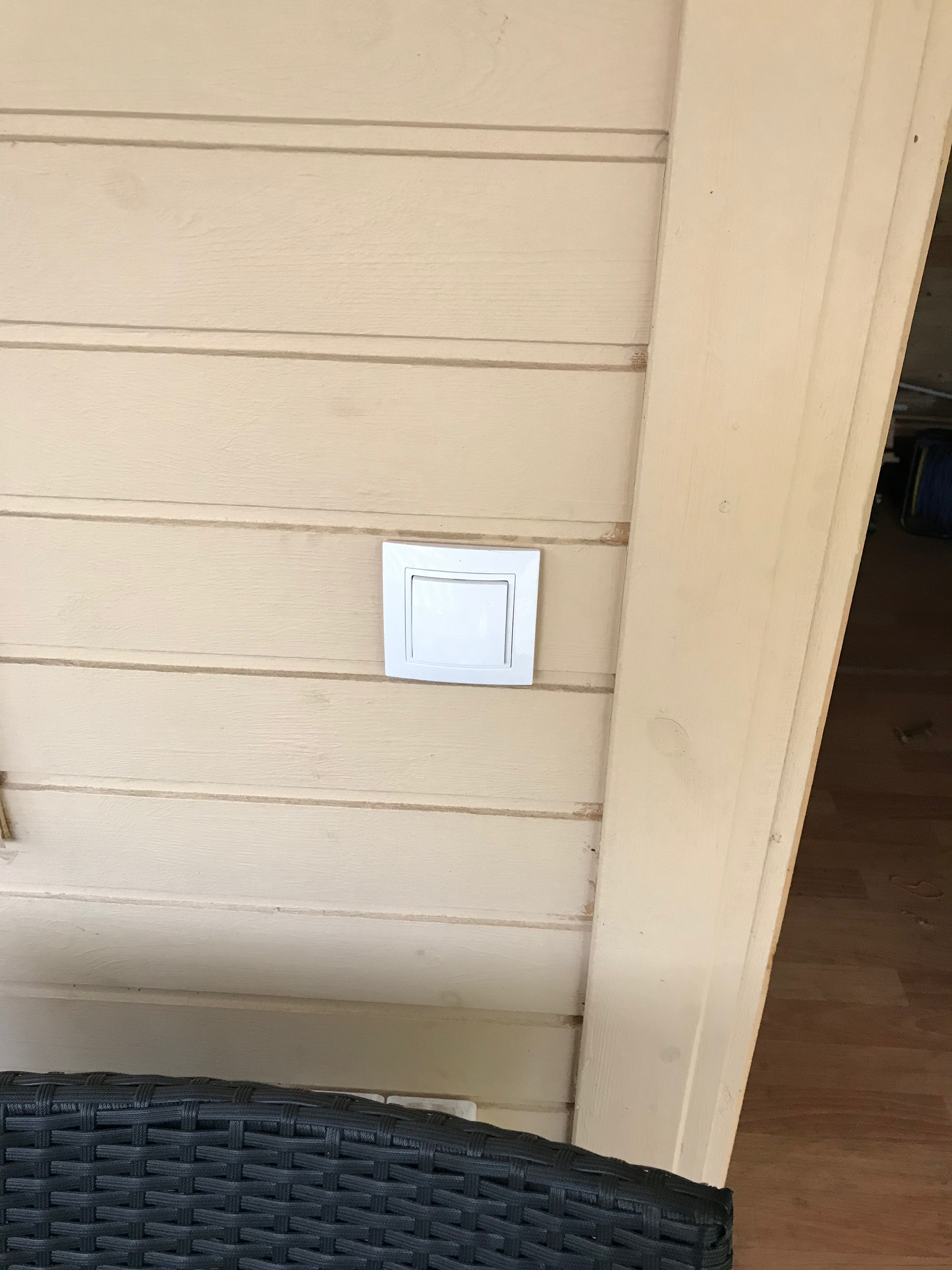
As a final result:
Remote 1 (replacing the old to the new):
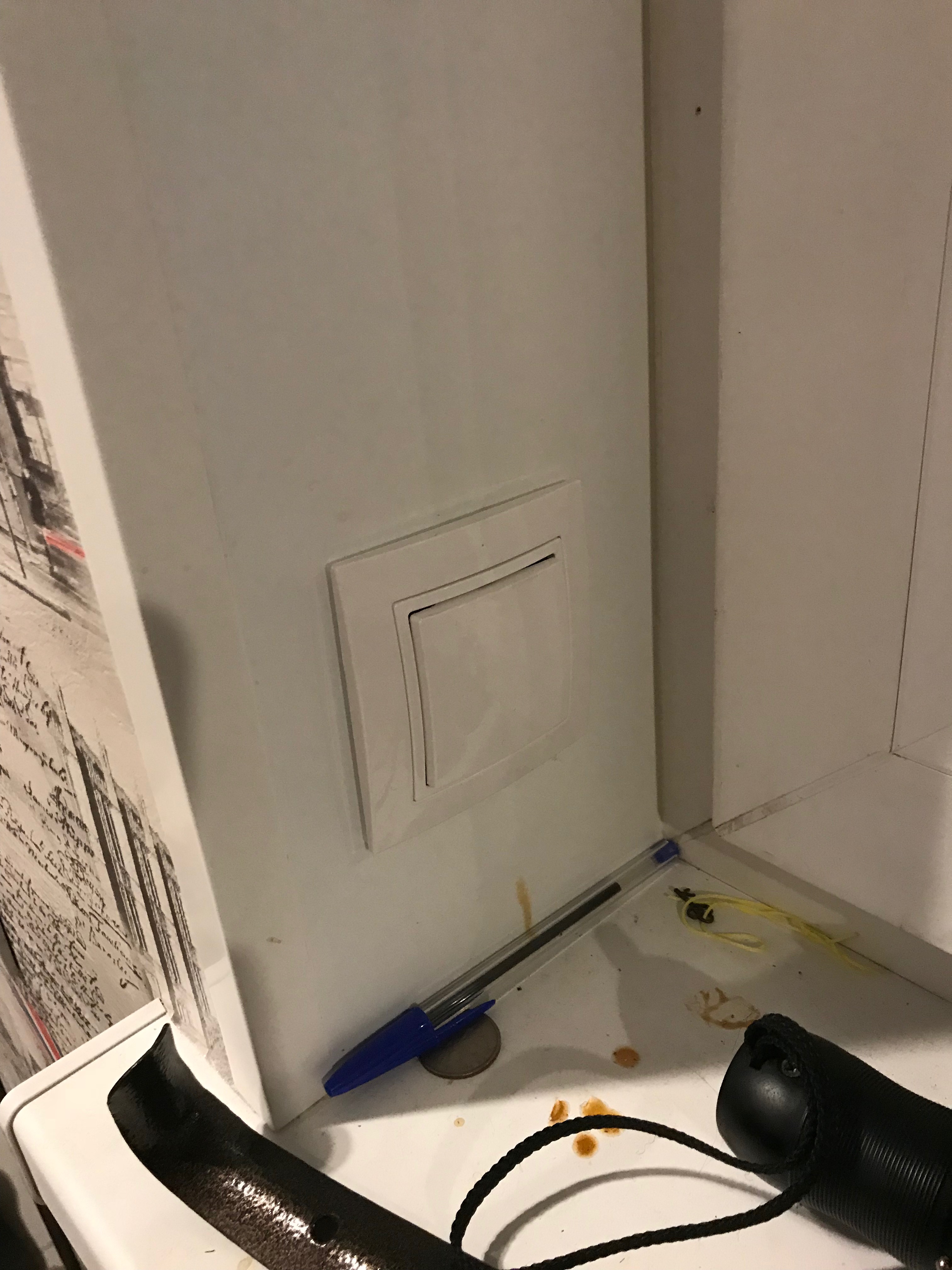
Remote number two, which is in the house:
Well, the light itself:
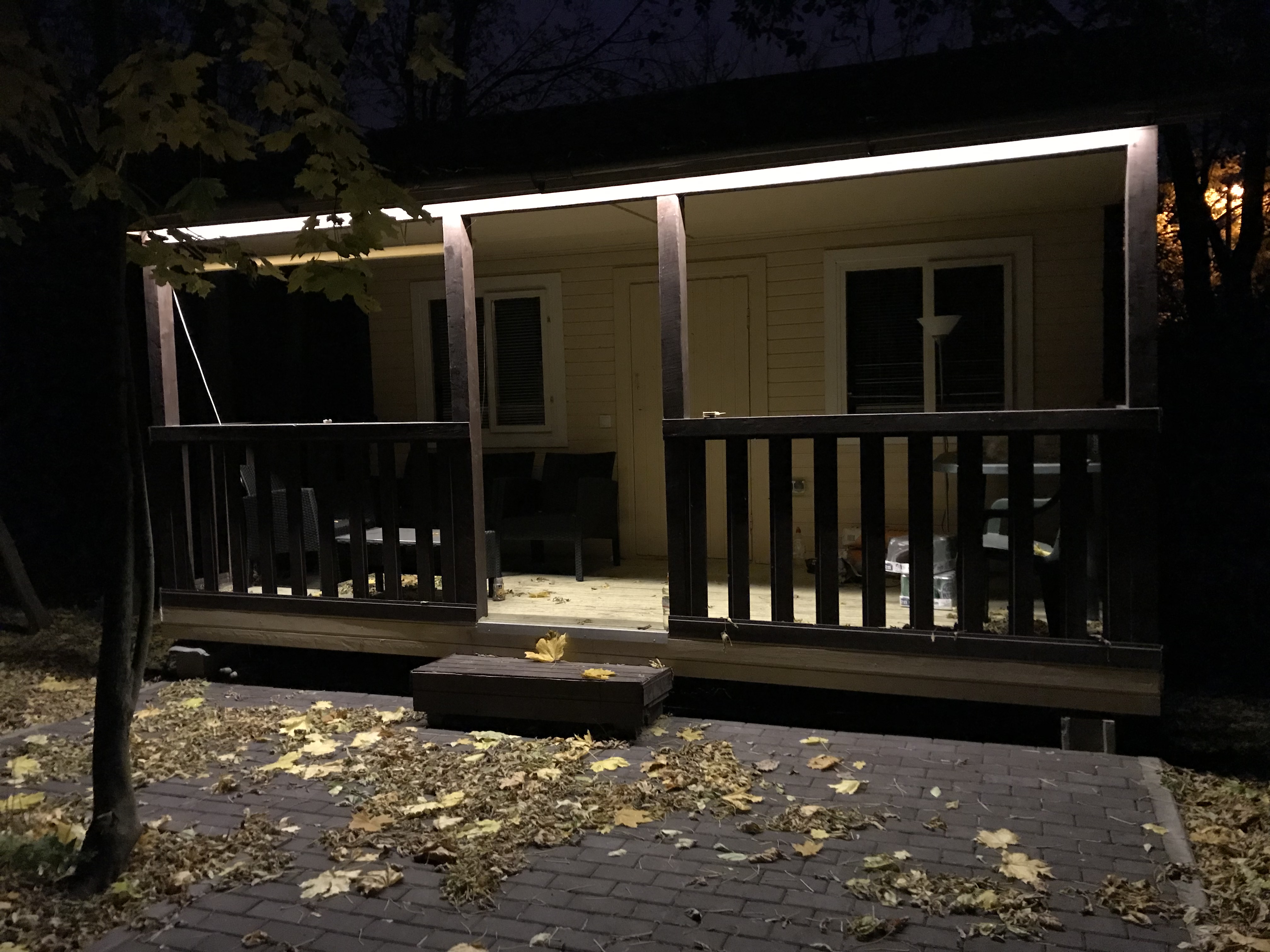
PS: The switched off tape looks like this, mounting it is even easier than the radio remote control, if you all thought to make LEDs or not - definitely yes.

Chat in Telegram t.me/Noolite
Source: https://habr.com/ru/post/373963/
All Articles