Electron microscope in the garage. Image capture
For the first time, see a microscope in a garage? Then start a fascinating reading with the first issue .
Since the previous publication, a lot of time has passed, it’s time to talk about successes :) All this time I devoted to the practical study of electronics (digital and analog), made about a dozen printed circuit boards (LUT method turned out to be quite good!), Looked through hundreds of circuits from different electron microscopes of various prescription of manufacture. And even gathered a couple of projects on the Arduino to practice on something.
After receiving the necessary experience and knowledge, he began to develop electronics and software for the microscope.
')
In the video - a demonstration of how implemented scanning and image capture. The board is not connected to anything yet, but the data is real (from the gradients of gray you can guess the moments when I connect the input to the scan outputs in X and Y).
The whole system was divided into the following independent modules:
I will make a reservation that the solutions described here do not claim to be the best and most optimal. At this stage, the most important is to achieve results with the least amount of time. Therefore, I will be very pleased with your constructive suggestions in the comments on how to do something better.
I think this is the most "tasty" part of the whole project. What a person will deal with when working with a microscope: see the image, adjust the settings - what the control panel used to serve.
The basis is Arduino Due, which has two digital-to-analog converters (D / A converters), which will be used to deflect the beam along the X and Y axes, and several analog-to-digital converters (ADC) to digitize the signal received from the sensors. The point is that the steps to install the beam at the desired point and read the signal are performed synchronously.
Generally, there are two different options for how to do a scan.
Due to the greater versatility, I implemented the first option. Then, if you wish, there is an opportunity to “shine” the beam to the desired point, and in the future you can even control the focusing in order to provide dynamic focus through the image. Write in the comments if you think that the second option is better. Continuous digitization of the signal in this microcontroller ( MK ) will be much faster, perhaps even it will be possible to achieve the frequency of 1 MHz.
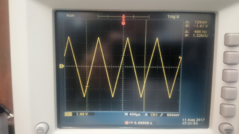
This is the line deviation signal generated by the board's DAC. That is, we read from left to right, then the next line from right to left, etc., you yourself understand why.
With computer MK communicates through a separate USB-interface.
The firmware of the MC itself is implemented by standard means using the Arduino IDE, but using direct access through the ports instead of the Arduino library function, which gives a significant increase in scanning speed. This topic has already been described in sufficient detail, but the essence is very simple: Arduino functions are universal and therefore have to do what is not necessary to do. For example, when reading a value from the same input tens of thousands of times per second, it is not at all necessary to set the number of the input being read, it is enough to do this before the cycle.
For fast data exchange with a PC, I developed a simple binary variable-messaging protocol. Each message contains a required header.
and the next payload.
For example, a scanned image line.
I was already advised to use the USB Bulk Transfer mode instead of the serial port simulation, but I have not yet mastered this method of working with Arduino Due.
This is not so trivial. I made the client part as a server on Node.JS + React.JS so that the microscope could be used not only locally. The serialport module provides good performance, and the image output is implemented through the element Canvas .
A visual demonstration of the work of all this is placed at the beginning of the article.
Separately, I dwell on the fact that a microscope requires a power source that not only has a large power reserve (due to possible impulse loads when controlling magnetic lenses), but also ensures a low level of output voltage ripple under load. A simple ATX power supply on the + 12V line could not provide decent quality, so a linear power supply unit based on a transformer from 1kVA UPS was designed, the secondary (former primary) windings of which were disconnected to obtain an independent AC voltage of about 15V.
From the constructed block it is required to receive bipolar food +12 and -12, and bipolar +5 and -5 volts.
The scheme is quite simple:

Two rectifiers, 33000 microfarads buffer capacitors, LM317 for each 12 volt channel with a TIP127 Darlington transistor, and a pair of L7805 for a 5 V channel.
Double-sided PCB, LUT method:

After soldering components, the board looks like this:
Some of the parts were reused from the failed ATX computer power supplies, including the wires. As the case is used the native case of the same UPS.
I already partially told about him in the last article , but the main thing that remained was to learn how to manage it all and to do everything qualitatively, because after all, 30kV at high current is not a toy.
The basis of the high voltage control module - Arduino Nano, connected by its outputs to:
- D / A converter that sets the reference voltage for the high-voltage unit
- the driver of the motor moving the slider on the cathode glow transformer
- the driver of the motor, which regulates (via a long dielectric rod) a variable resistor, which sets the voltage shift of the cathode relative to the Weelth cylinder
- control of the cathode ignition relay using the scheme that I mentioned in the last article
I also made a measurement of the filament current, but I did not fully test this circuit and it turned out that the sensitivity is too low, it will be necessary to redo it later.
With the cover removed, the device looks like this:
All these wires are neatly tidied up into the iron case from a former television receiver (or something like that), which well shields possible interference from the “aquarium”. At least, after all this was placed in the case and done “properly”, the Arduino Nano stopped hanging shortly after switching on the high voltage. Yes, and aesthetically design the finished, working modules in boxes - quite nice and convenient.
Many people already ask when the microscope will finally work. So - soon! :)
It remains to make a sensor of secondary electrons (-1kV source, + 12kV source, amplifier), or connect an absorbed current amplifier (ready, but the picture from it will not be as beautiful as with SED).
And to deal with the amplifier for the beam deflection system, there are some tricks there.
I manage the lenses just from the laboratory power supply, but I plan to buy DACs (even 10-bit will go, but first I’ll find out which ones are better), they will probably need about a dozen there, considering how many adjustment possibilities there are in this column, and make for them a common control board on the SPI-bus, for example.
Visiting the country in which Evangelista was born and lived, Torricelli could not resist and went to the University of Rome , where the thematic exhibition of Nano-Innovations devoted to various equipment, including microscopes, was held.
Greetings to all readers from this sunny country!

In the next series - a story about electron detectors
Since the previous publication, a lot of time has passed, it’s time to talk about successes :) All this time I devoted to the practical study of electronics (digital and analog), made about a dozen printed circuit boards (LUT method turned out to be quite good!), Looked through hundreds of circuits from different electron microscopes of various prescription of manufacture. And even gathered a couple of projects on the Arduino to practice on something.
After receiving the necessary experience and knowledge, he began to develop electronics and software for the microscope.
')
In the video - a demonstration of how implemented scanning and image capture. The board is not connected to anything yet, but the data is real (from the gradients of gray you can guess the moments when I connect the input to the scan outputs in X and Y).
The whole system was divided into the following independent modules:
- Image capture and PC interface.
- Power supply for precise elements, and power supply for power elements (relays, valve, etc.)
- Management of magnetic lenses, static. Condenser, focus, beam shift at the beginning, stigmator - all this is set independently of the scan.
- Control beam deflection. Directly responsible for moving the beam along the pattern. The increase is set here.
- Vacuum system control
- High voltage and cathode glow control
- -1kV High Voltage Source for PMT in Secondary Electron Detector ( SED )
- High voltage source + 12kV for SED collector (without it, the detector will operate in the registration of elastically reflected electrons - BSE)
I will make a reservation that the solutions described here do not claim to be the best and most optimal. At this stage, the most important is to achieve results with the least amount of time. Therefore, I will be very pleased with your constructive suggestions in the comments on how to do something better.
I. Image Capture
I think this is the most "tasty" part of the whole project. What a person will deal with when working with a microscope: see the image, adjust the settings - what the control panel used to serve.
Hardware
The basis is Arduino Due, which has two digital-to-analog converters (D / A converters), which will be used to deflect the beam along the X and Y axes, and several analog-to-digital converters (ADC) to digitize the signal received from the sensors. The point is that the steps to install the beam at the desired point and read the signal are performed synchronously.
Generally, there are two different options for how to do a scan.
- Two cycles of X and Y, inside the installation of the beam at the desired point by outputting the desired values to the analog output through the DAC, and digitizing the value from the sensor.
- Managed sawtooth generators with sync pulses, and the Arduino continuously digitizes the signal, breaking it in sync pulses.
Due to the greater versatility, I implemented the first option. Then, if you wish, there is an opportunity to “shine” the beam to the desired point, and in the future you can even control the focusing in order to provide dynamic focus through the image. Write in the comments if you think that the second option is better. Continuous digitization of the signal in this microcontroller ( MK ) will be much faster, perhaps even it will be possible to achieve the frequency of 1 MHz.
This is the line deviation signal generated by the board's DAC. That is, we read from left to right, then the next line from right to left, etc., you yourself understand why.
With computer MK communicates through a separate USB-interface.
Software part
MK firmware
The firmware of the MC itself is implemented by standard means using the Arduino IDE, but using direct access through the ports instead of the Arduino library function, which gives a significant increase in scanning speed. This topic has already been described in sufficient detail, but the essence is very simple: Arduino functions are universal and therefore have to do what is not necessary to do. For example, when reading a value from the same input tens of thousands of times per second, it is not at all necessary to set the number of the input being read, it is enough to do this before the cycle.
Messaging protocol
For fast data exchange with a PC, I developed a simple binary variable-messaging protocol. Each message contains a required header.
typedef struct { uint32_t magic; uint16_t type; uint16_t len; } MSG_HEADER; and the next payload.
For example, a scanned image line.
typedef struct { uint16_t lineNumber; uint8_t pixels[MAX_SCAN_WIDTH]; } MSG_SCANLINE; I was already advised to use the USB Bulk Transfer mode instead of the serial port simulation, but I have not yet mastered this method of working with Arduino Due.
Client part
This is not so trivial. I made the client part as a server on Node.JS + React.JS so that the microscope could be used not only locally. The serialport module provides good performance, and the image output is implemented through the element Canvas .
A visual demonstration of the work of all this is placed at the beginning of the article.
Ii. Power Supply
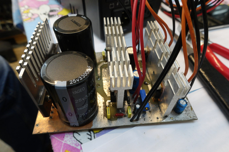
Separately, I dwell on the fact that a microscope requires a power source that not only has a large power reserve (due to possible impulse loads when controlling magnetic lenses), but also ensures a low level of output voltage ripple under load. A simple ATX power supply on the + 12V line could not provide decent quality, so a linear power supply unit based on a transformer from 1kVA UPS was designed, the secondary (former primary) windings of which were disconnected to obtain an independent AC voltage of about 15V.
From the constructed block it is required to receive bipolar food +12 and -12, and bipolar +5 and -5 volts.
The scheme is quite simple:
Two rectifiers, 33000 microfarads buffer capacitors, LM317 for each 12 volt channel with a TIP127 Darlington transistor, and a pair of L7805 for a 5 V channel.
Double-sided PCB, LUT method:
After soldering components, the board looks like this:
Some of the parts were reused from the failed ATX computer power supplies, including the wires. As the case is used the native case of the same UPS.
Iii. High voltage and cathode glow control
I already partially told about him in the last article , but the main thing that remained was to learn how to manage it all and to do everything qualitatively, because after all, 30kV at high current is not a toy.
The basis of the high voltage control module - Arduino Nano, connected by its outputs to:
- D / A converter that sets the reference voltage for the high-voltage unit
- the driver of the motor moving the slider on the cathode glow transformer
- the driver of the motor, which regulates (via a long dielectric rod) a variable resistor, which sets the voltage shift of the cathode relative to the Weelth cylinder
- control of the cathode ignition relay using the scheme that I mentioned in the last article
I also made a measurement of the filament current, but I did not fully test this circuit and it turned out that the sensitivity is too low, it will be necessary to redo it later.
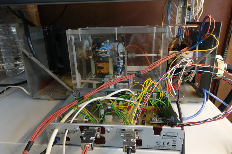
With the cover removed, the device looks like this:
All these wires are neatly tidied up into the iron case from a former television receiver (or something like that), which well shields possible interference from the “aquarium”. At least, after all this was placed in the case and done “properly”, the Arduino Nano stopped hanging shortly after switching on the high voltage. Yes, and aesthetically design the finished, working modules in boxes - quite nice and convenient.
Go ahead!
Many people already ask when the microscope will finally work. So - soon! :)
It remains to make a sensor of secondary electrons (-1kV source, + 12kV source, amplifier), or connect an absorbed current amplifier (ready, but the picture from it will not be as beautiful as with SED).
And to deal with the amplifier for the beam deflection system, there are some tricks there.
I manage the lenses just from the laboratory power supply, but I plan to buy DACs (even 10-bit will go, but first I’ll find out which ones are better), they will probably need about a dozen there, considering how many adjustment possibilities there are in this column, and make for them a common control board on the SPI-bus, for example.
PS
Visiting the country in which Evangelista was born and lived, Torricelli could not resist and went to the University of Rome , where the thematic exhibition of Nano-Innovations devoted to various equipment, including microscopes, was held.
Greetings to all readers from this sunny country!
In the next series - a story about electron detectors
Source: https://habr.com/ru/post/373945/
All Articles