Retro electromoped "Cherry". Story 1 - from concept to test drive
Greetings dear Giktayms! I propose to introduce the experience of acquiring a two-wheeled friend for unhurried walks in rough terrain.
A gift from the past, looking to the future
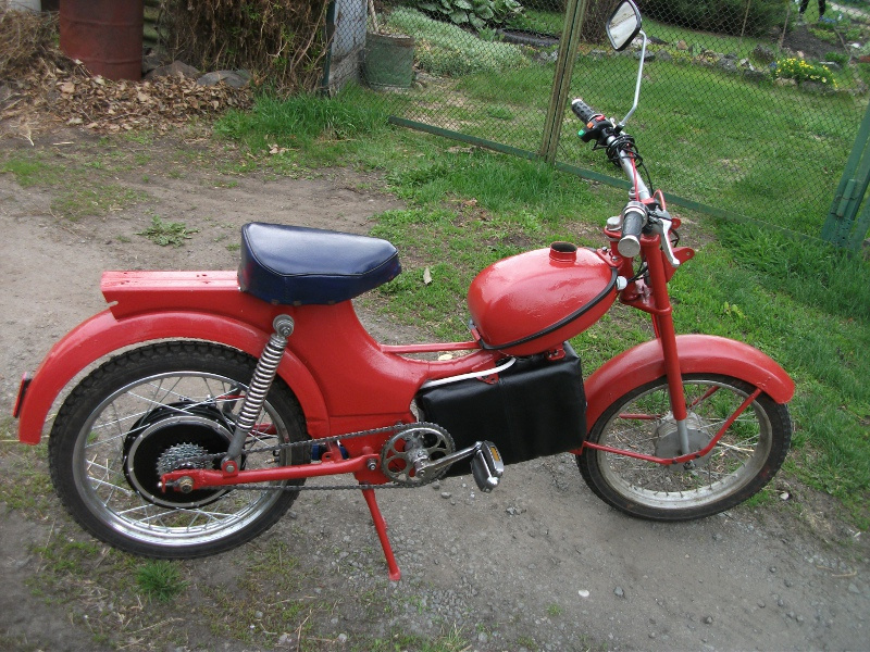
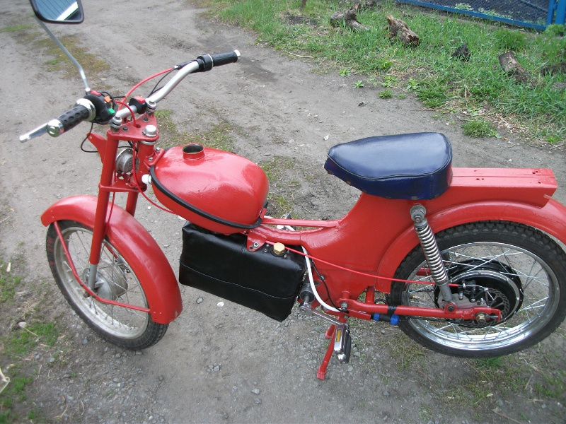
At the beginning of 2014, I was lucky enough to save my childhood dream from scrap metal - the two-speed moped Riga-12 of 1975. For several months, the miracle of Soviet technology was dismantled to a screw, cleaned, slightly podvareno (fell off the upper yoke of the steering column and stand hooves, cracked saddle frame), repainted with hammer enamel, assembled, equipped with electronic ignition and, finally, started and drove off. Yes, this bike deserved to restore it! Relatively light, with a low center of gravity, stable, controlled, predictable and comfortably behaving on irregularities with which in the village and the forest - our habitat area - the routes are more than abundant. Only one thing failed and disappointed - a noisy, dirty and unreliable two-stroke S-57 engine.
')
Amateur mopeds will argue, they say, you just need to be able to handle such a motor, and then it will mostly not let you down, but please. I do not argue, antique engines still faithfully serve orange grandfathers, being wonderful representatives of living history. How many lucky ones in their time gave the first real motor vehicle in life, the feeling of flying on a two-wheeled vehicle, the freedom of magic skating in nature and in the city, which was then more spacious and greener, invaluable basics of handling and understanding technology!
The spirit of the 20th century, which brought me and many respected colleagues, deserves to be mentioned, felt and thought. Vehicles, scientific equipment, industrial and household appliances were perceived by the people who created them, served them, acquired and used not as consumables and commodity units worth a certain amount of money (or, more precisely, can and should bring them). ), and even with the planned aging and proprietary bondage, but as wonderful complex systems that embodied the achievements of science and design genius. Cars, motorcycles, tape recorders and the pinnacle of progress - computers - consisted for us, children of the era of scientific and technological progress, not from rubles, rupees, bitcoins and promotional marketing points, but from technological details, and not the vulgar number of rupees, but sacral quality of elements and the sacrament of their interaction. We admired the priesthood of the Master, who is able to repair the TV, - a wonderful window into the world of children's and youth films and programs, informative and inspiring. And learning how to self-maintain your bicycle, moped, electric appliance, even just to repair furniture or clothes, was for every son and daughter of the Masters time great pride, the system-forming aspect of self-determination. And even more so to collect or even construct a homemade, acting, real thing! I can, therefore, exist, live, develop, cognize and create, use existing culture and create my own things on its base, which I can use!
Things then were not temporary shelters for earnings, but really things weighty, prophetic and durable. Even when it came to low-cost mass moped, designed only to meet the needs of the state and the population in an affordable two-wheeled car for adolescents and pensioners, in order to perform utilitarian tasks and the formation of basic knowledge, skills, driving skills of transport and maintenance mechanisms. Two-speed Riga turned out very beautiful and sturdy. Beautiful steel frame, slightly susceptible to corrosion, a solid margin of safety, a good layout, decent design.
Space travel, electronics, computers and robots were things that developed rapidly and inspired. By this we lived then, by this one can live now. Therefore, the vintage base of Riga-12 with its retro-futuristic appearance in the spirit of robots, aviation and space is so perfect for a steel skate. And therefore I will replace her simplified clone of the antediluvian Czech three-speed motor with an electric motor. Cute vintage mopeds, such as Rigi and their ancestors of Java, now rare Lvivians and Triumph Fips, unsurpassed in their beauty, like many other representatives of the technology of the second half of the 20th century, did not look to the past, but to the future. Environmentally friendly brushless motor with digital electronic control on a single-chip microcomputer - is this not a dream? Nothing needs to be poured anywhere, to start with tricks, it is difficult to manage, so as not to stall, not to overheat, not to grab. Charge from the mains, solar panels, wind turbines, turned on and - go!
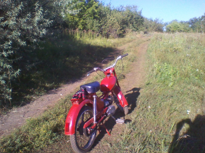
To whom how, but for me biker happiness is not in the motor from the past, ambiguous romance fiddling with it, specific strong smells and sounds, but in the unity of a rider, bike and terrain, the ability to hear and smell nature, to leave at dawn for mushrooms, without waking the neighbors , do not disturb the delicate balance of life in the forest or steppe. The appearance of the electric motorcycle, in my opinion, remains harmoniously vintage, and its standard filling is replaced with the one that was only dreamed of at the time of its production. And this is not the destruction of a technical monument of antiquity, which could be restored, preserved and put in a museum, but the extension of a full-fledged life of a good apparatus at a new level.
For me personally, the main interest in the project was testing of lead-acid batteries in harsh operating conditions, which succeeded one hundred percent, and even more. Therefore, soon after the construction, the electric bike was handed over to a good friend, fond of two-wheeled personal transport, steampunk and retro-futurism, which very much requested to create something similar for it. And I continue to outline the prospects for the acquisition with a modification or construction of a lighter and minimalist projectile for movement, recovery and joy.
')
Amateur mopeds will argue, they say, you just need to be able to handle such a motor, and then it will mostly not let you down, but please. I do not argue, antique engines still faithfully serve orange grandfathers, being wonderful representatives of living history. How many lucky ones in their time gave the first real motor vehicle in life, the feeling of flying on a two-wheeled vehicle, the freedom of magic skating in nature and in the city, which was then more spacious and greener, invaluable basics of handling and understanding technology!
The spirit of the 20th century, which brought me and many respected colleagues, deserves to be mentioned, felt and thought. Vehicles, scientific equipment, industrial and household appliances were perceived by the people who created them, served them, acquired and used not as consumables and commodity units worth a certain amount of money (or, more precisely, can and should bring them). ), and even with the planned aging and proprietary bondage, but as wonderful complex systems that embodied the achievements of science and design genius. Cars, motorcycles, tape recorders and the pinnacle of progress - computers - consisted for us, children of the era of scientific and technological progress, not from rubles, rupees, bitcoins and promotional marketing points, but from technological details, and not the vulgar number of rupees, but sacral quality of elements and the sacrament of their interaction. We admired the priesthood of the Master, who is able to repair the TV, - a wonderful window into the world of children's and youth films and programs, informative and inspiring. And learning how to self-maintain your bicycle, moped, electric appliance, even just to repair furniture or clothes, was for every son and daughter of the Masters time great pride, the system-forming aspect of self-determination. And even more so to collect or even construct a homemade, acting, real thing! I can, therefore, exist, live, develop, cognize and create, use existing culture and create my own things on its base, which I can use!
Things then were not temporary shelters for earnings, but really things weighty, prophetic and durable. Even when it came to low-cost mass moped, designed only to meet the needs of the state and the population in an affordable two-wheeled car for adolescents and pensioners, in order to perform utilitarian tasks and the formation of basic knowledge, skills, driving skills of transport and maintenance mechanisms. Two-speed Riga turned out very beautiful and sturdy. Beautiful steel frame, slightly susceptible to corrosion, a solid margin of safety, a good layout, decent design.
Space travel, electronics, computers and robots were things that developed rapidly and inspired. By this we lived then, by this one can live now. Therefore, the vintage base of Riga-12 with its retro-futuristic appearance in the spirit of robots, aviation and space is so perfect for a steel skate. And therefore I will replace her simplified clone of the antediluvian Czech three-speed motor with an electric motor. Cute vintage mopeds, such as Rigi and their ancestors of Java, now rare Lvivians and Triumph Fips, unsurpassed in their beauty, like many other representatives of the technology of the second half of the 20th century, did not look to the past, but to the future. Environmentally friendly brushless motor with digital electronic control on a single-chip microcomputer - is this not a dream? Nothing needs to be poured anywhere, to start with tricks, it is difficult to manage, so as not to stall, not to overheat, not to grab. Charge from the mains, solar panels, wind turbines, turned on and - go!
To whom how, but for me biker happiness is not in the motor from the past, ambiguous romance fiddling with it, specific strong smells and sounds, but in the unity of a rider, bike and terrain, the ability to hear and smell nature, to leave at dawn for mushrooms, without waking the neighbors , do not disturb the delicate balance of life in the forest or steppe. The appearance of the electric motorcycle, in my opinion, remains harmoniously vintage, and its standard filling is replaced with the one that was only dreamed of at the time of its production. And this is not the destruction of a technical monument of antiquity, which could be restored, preserved and put in a museum, but the extension of a full-fledged life of a good apparatus at a new level.
For me personally, the main interest in the project was testing of lead-acid batteries in harsh operating conditions, which succeeded one hundred percent, and even more. Therefore, soon after the construction, the electric bike was handed over to a good friend, fond of two-wheeled personal transport, steampunk and retro-futurism, which very much requested to create something similar for it. And I continue to outline the prospects for the acquisition with a modification or construction of a lighter and minimalist projectile for movement, recovery and joy.
Selection and installation of electric motor
So, we build by electrokast on the basis of Riga-12. For a start we will decide on the drive. Choose from the following options.
The carriage motor is a specialized solution for a bicycle frame and speed control with asterisks. It is expensive, power is usually small, designed more to help pedaling, transmits traction through a bicycle-type chain. And Cherry - the device is quite heavy, even in comparison with the bikes of the USSR, not to mention the modern ones, and the transfer of all the power for a thin chain is an excessive load. No good.
The electric motor on the trunk, in place of a gasoline engine, or even a cylinder or crank camera, while maintaining the standard gearbox. Craftsmen created many options, each other extravagant. Screwdrivers, angle grinders (“grinders”), collector engines from car heaters fans, motors from the modellers' arsenal are used ... All this is noisy, not very reliable and aesthetically pleasing, often has a small resource, requires complicated transmission, and It loses a lot of energy, which is critical for an electric bike. Finally, the automobile generator, which has already become a classic, as an engine, with or without rewinding, maintaining the field winding or replacing it with permanent magnets. A good, reliable, powerful AC machine, but there are questions about cooling and dust and moisture protection, and for a small moped it is cumbersome. With this engine in my craft there will be little space for traction battery and it will be difficult to put the pedals.
Yes, exactly the pedals! A cherry remains a moped, only an electric one, or, in other words, it will become a heavy electric bicycle, and instead of a pedal trigger mechanism, it will receive a full-fledged one-speed pedal drive, a carriage leading and driven asterisks, a stub-roller chain. This will help to overcome difficult areas, keep yourself in physical form, as well as with relative, given the severity of the device, comfort to get to the house in case of discharge or malfunction of the electric drive.
Therefore, we choose the motor-wheel. But what, gear, with its noise and wear plastic gears, or direct drive? The rim of a moped is only 16 motorcycle inches, it is 20 "in bicycle count. With the same torque and rotational speed, the tractive effort is higher, and the speed is lower, the smaller the wheel diameter, and vice versa. Our gearbox does not need a gear, therefore A direct drive motor hub is clearly suitable, and a rated power of 1 kW is enough.
Here are just the rims we have under 32 spokes, and the motor hub on the market is 36 ... You can buy a rim from Mokik ZiD Pilot, it is identical to the rims of mopeds Carpathians, Verkhovyna, Riga, but it has holes for 36 spokes. And you can contact the good Chinese, who will manufacture an electric motor with as many spokes as we need. I will share the link to the motor I purchased. The rest of the components I bought from different vendors, for the sake of cheapness and the study of the range. Some of them have failed, as further, but the motor-hub pleased in everything.
To calculate the length of the spokes, we will use the SpoCalc program, or some online calculator, they all give almost equal results. We will speak in two crosses, as it was in stock. Due to the larger diameter of the motor hub in comparison with the standard brake sleeve, the nipples will fit into the holes at a sharper angle. The rim, fortunately, is not pistoned, and a non-standard angle will not cause problems. On the contrary, more tangential, as they say at bicycle masters, the pattern of the spokes is not only beautiful, but also better in terms of transferring the rim of torque from the sleeve.
ERD (effective diameter) of a 16-inch rim of a USSR 2-speed moped is 380 mm, the shift of the spoke holes from the center is 4 mm. The diameter of the circle with holes for the spokes of our Konhis-motor is 230, the total length of the axis is 210, the width between the dropouts is 135, the thickness of the hub is at the place of the holes 35, and it is located exactly in the middle of the axis without shifting left or right. As a result, with 2 crosses and 32 needles, we need them with a length of 135 mm and a thickness of 12G. The photo of the assembled wheel has already been and still will be, but for now we will work on its reliable fastening.

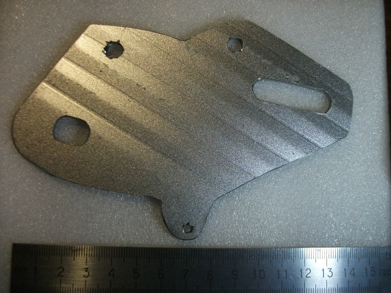
We maximize the dropouts by welding the plates, because all the torque is transmitted through the axis. My little motor, by the way, is not flimsy tubular, but solid, with a cable groove. Not a trifle, and nice. To install a bicycle brake, (cable drive, the cheapest, the bike is not going for speed, but for passing, and electric braking will help), we cut a figured plate out of steel. It will also serve as an additional torsion lever, passing the moment to the shock absorber mounting bolt to the rear fork, bypassing the dropout. When adjusting the chain tension, the plate will move with the wheel axis, so that the position of the brake caliper relative to the disc will remain unchanged.
The carriage motor is a specialized solution for a bicycle frame and speed control with asterisks. It is expensive, power is usually small, designed more to help pedaling, transmits traction through a bicycle-type chain. And Cherry - the device is quite heavy, even in comparison with the bikes of the USSR, not to mention the modern ones, and the transfer of all the power for a thin chain is an excessive load. No good.
The electric motor on the trunk, in place of a gasoline engine, or even a cylinder or crank camera, while maintaining the standard gearbox. Craftsmen created many options, each other extravagant. Screwdrivers, angle grinders (“grinders”), collector engines from car heaters fans, motors from the modellers' arsenal are used ... All this is noisy, not very reliable and aesthetically pleasing, often has a small resource, requires complicated transmission, and It loses a lot of energy, which is critical for an electric bike. Finally, the automobile generator, which has already become a classic, as an engine, with or without rewinding, maintaining the field winding or replacing it with permanent magnets. A good, reliable, powerful AC machine, but there are questions about cooling and dust and moisture protection, and for a small moped it is cumbersome. With this engine in my craft there will be little space for traction battery and it will be difficult to put the pedals.
Yes, exactly the pedals! A cherry remains a moped, only an electric one, or, in other words, it will become a heavy electric bicycle, and instead of a pedal trigger mechanism, it will receive a full-fledged one-speed pedal drive, a carriage leading and driven asterisks, a stub-roller chain. This will help to overcome difficult areas, keep yourself in physical form, as well as with relative, given the severity of the device, comfort to get to the house in case of discharge or malfunction of the electric drive.
Therefore, we choose the motor-wheel. But what, gear, with its noise and wear plastic gears, or direct drive? The rim of a moped is only 16 motorcycle inches, it is 20 "in bicycle count. With the same torque and rotational speed, the tractive effort is higher, and the speed is lower, the smaller the wheel diameter, and vice versa. Our gearbox does not need a gear, therefore A direct drive motor hub is clearly suitable, and a rated power of 1 kW is enough.
Here are just the rims we have under 32 spokes, and the motor hub on the market is 36 ... You can buy a rim from Mokik ZiD Pilot, it is identical to the rims of mopeds Carpathians, Verkhovyna, Riga, but it has holes for 36 spokes. And you can contact the good Chinese, who will manufacture an electric motor with as many spokes as we need. I will share the link to the motor I purchased. The rest of the components I bought from different vendors, for the sake of cheapness and the study of the range. Some of them have failed, as further, but the motor-hub pleased in everything.
To calculate the length of the spokes, we will use the SpoCalc program, or some online calculator, they all give almost equal results. We will speak in two crosses, as it was in stock. Due to the larger diameter of the motor hub in comparison with the standard brake sleeve, the nipples will fit into the holes at a sharper angle. The rim, fortunately, is not pistoned, and a non-standard angle will not cause problems. On the contrary, more tangential, as they say at bicycle masters, the pattern of the spokes is not only beautiful, but also better in terms of transferring the rim of torque from the sleeve.
ERD (effective diameter) of a 16-inch rim of a USSR 2-speed moped is 380 mm, the shift of the spoke holes from the center is 4 mm. The diameter of the circle with holes for the spokes of our Konhis-motor is 230, the total length of the axis is 210, the width between the dropouts is 135, the thickness of the hub is at the place of the holes 35, and it is located exactly in the middle of the axis without shifting left or right. As a result, with 2 crosses and 32 needles, we need them with a length of 135 mm and a thickness of 12G. The photo of the assembled wheel has already been and still will be, but for now we will work on its reliable fastening.
We maximize the dropouts by welding the plates, because all the torque is transmitted through the axis. My little motor, by the way, is not flimsy tubular, but solid, with a cable groove. Not a trifle, and nice. To install a bicycle brake, (cable drive, the cheapest, the bike is not going for speed, but for passing, and electric braking will help), we cut a figured plate out of steel. It will also serve as an additional torsion lever, passing the moment to the shock absorber mounting bolt to the rear fork, bypassing the dropout. When adjusting the chain tension, the plate will move with the wheel axis, so that the position of the brake caliper relative to the disc will remain unchanged.
We design the pedal drive
So, we take the carriage knot, the pedals and the front star from the bike that ordered to live long, weld the fasteners under the moped frame, set the chain and enjoy? Not so simple. My bike is a fat one, its frame is much wider than a bicycle one (even a fatbike), and the pedal axis of some Ural, Kama or Desna will be too short. But we prudently saved the pedal shaft from the standard engine W-57, it is exactly the length that is needed. They lay in stocks and well-preserved connecting rods, (in fact, cranks, but cyclists call them that), from a teenage bicycle, just under the wedge, the desired length of 125 mm, and with a leading sprocket of a suitable diameter. A star from an adult bicycle would force us to move the pedal axle too forward from its initial position in the motor, as it would otherwise touch the axis of the rear suspension pendulum. And we want a traction drive, not a high-speed drive, because the little leading asterisk is what the doctor prescribed. It should be slightly more to the left of the connecting rod than usual, so we cut it off from it and weld it to a fragment of another, broken, with a wedge fastening, for which we will cut a groove in the right place of the pedal axis. All places of welding process rust modifier.

The carriage will be constructed from four ball bearings (in bicycle terminology industrial, or industrial bearings), two stoppers and two glands, and its body will be an aluminum pipe from a distributing gun for petrol stations, the remains of which finally awaited useful applications. Argon and aluminum welding wire is not yet available, so we are thinking of fixing a homemade carriage to the frame of the moped from what is.
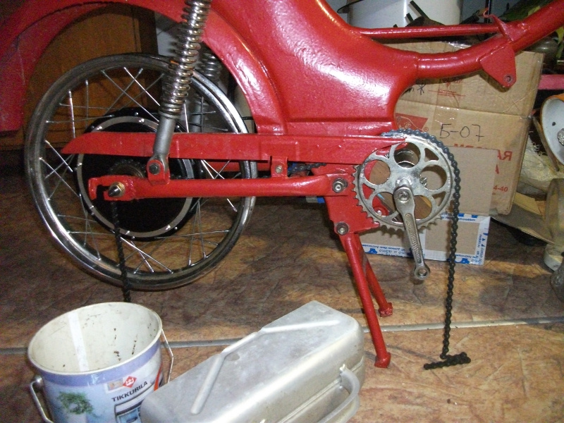
A number of assessments and walking around and around led to the idea of clamping the carriage between the yoke and the bed in a wooden bar, which at a good angle enters the cavity of the frame and even is clamped there by forces operating during operation. Reliable fixation is carried out by two brackets made of sheet steel, installed in place of the mounting tides crankcase full-time engine. We don’t modify the frame of Riga-12 in this place, nothing needs to be cut, cut, drilled and welded, which, of course, is very good. I don’t know yet how long such a “collective farm” mounting of the pedal mechanism will serve, but it’s necessary to arrange running trials and enjoy the first season. Then it will be possible (and necessary) to make a more capital carriage assembly with fastening.
The carriage will be constructed from four ball bearings (in bicycle terminology industrial, or industrial bearings), two stoppers and two glands, and its body will be an aluminum pipe from a distributing gun for petrol stations, the remains of which finally awaited useful applications. Argon and aluminum welding wire is not yet available, so we are thinking of fixing a homemade carriage to the frame of the moped from what is.
A number of assessments and walking around and around led to the idea of clamping the carriage between the yoke and the bed in a wooden bar, which at a good angle enters the cavity of the frame and even is clamped there by forces operating during operation. Reliable fixation is carried out by two brackets made of sheet steel, installed in place of the mounting tides crankcase full-time engine. We don’t modify the frame of Riga-12 in this place, nothing needs to be cut, cut, drilled and welded, which, of course, is very good. I don’t know yet how long such a “collective farm” mounting of the pedal mechanism will serve, but it’s necessary to arrange running trials and enjoy the first season. Then it will be possible (and necessary) to make a more capital carriage assembly with fastening.
Motor wheel controller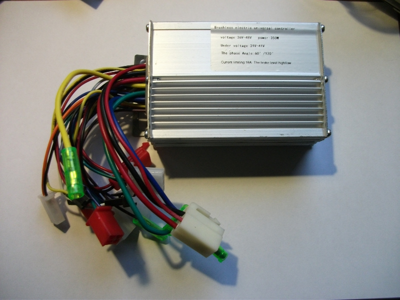
Brushless motor controller (BLDC) purchased for the cheapest test. It is called Universal, universal, for the ability to work at different voltages, both with and without Hall sensors, automatically determine the phase and phase angle, learn and memorize the direction of rotation, and everything is possible in the field, it is enough to close two wiring. The controller is often positioned as a repair, they are replaced with a regular one in the event of a Hall sensor failure, if there are reasons to refrain from replacing them. The power rating of this variant is 350 W, but 18 amps at 48 volts DC is almost a kilowatt. If the controller does not like or spoil, I will redo it or even develop my own, but, looking ahead, I will say that the first trips are very pleased. It seems that the controller is necessary.
According to the good tradition of electric transport lovers, I will share the data in my specimen. Bracket bent on the mail, it's not scary. The presence of debris inside the block in the form of a couple of solder pieces is more serious, but we are craftsmen, so we’ll examine the device before we try it on, remove the debris, eliminate the seals and short-circuits if it is detected. I did not have them.
The sticker on the case-radiator reads as follows.
Brushless electric universal controller
voltage: 36V-48V power: 350w
Under voltage: 31V-41V
The phase Angle: 60 ° / 120 °
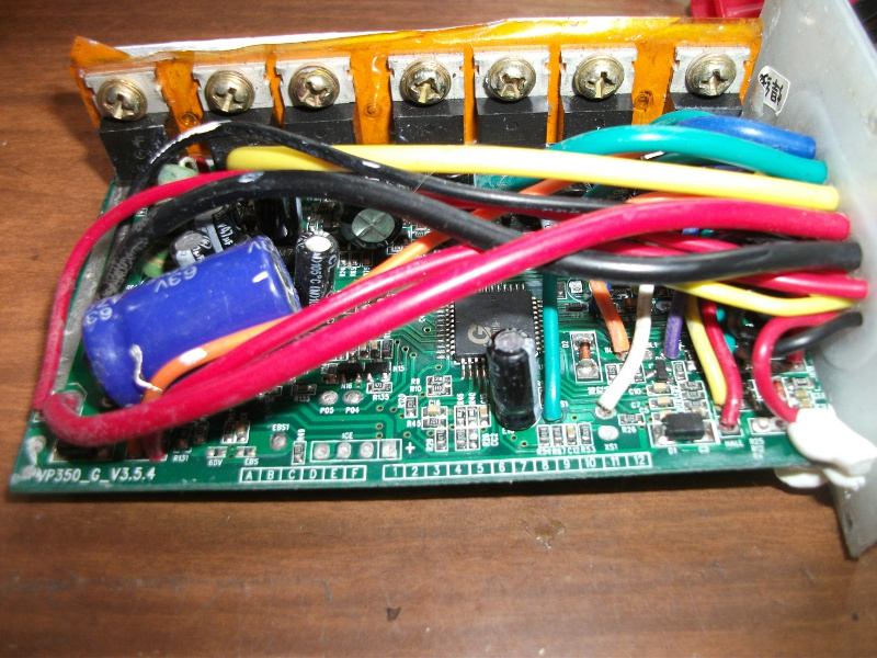
The controller has the following conclusions.
White connector - to the traction battery and anti-theft lock or switch.
Black thick wire - battery minus, power ground.
Red thick - plus batteries, power supply.
Red thin - VCCO - plus batteries through the lock (if available), power to the electronics.
The red connector is for charging.
Red - plus batteries, parallel to the red one.
Black - minus battery weight.
White connector - to the accelerator handle.
Black is mass.
Red - + 4.3V.
Green - analog input from the Hall sensor accelerator handle.
Black plug dad
White - weight
Black jack mom
White - XX - turns on self-learning mode when short to ground before turning on the power.
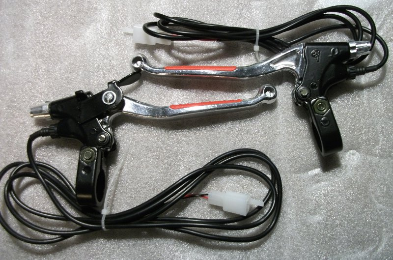
White connector - to the brake levers, with a short to ground (bicycle wiring option).
Orange - Brake LOW, discrete input, pulled through a resistor at + 5V.
Black is mass.
White connector - to the brake levers, in the case of the scooter wiring option.
Purple - Brake HI - is connected to the plus wire of the brake light, through the microswitches of the brake handles going to the battery plus.
In an electric bike, only one of these signals can be used, either Brake LOW or Brake HI.
Red connector - gearshift.
Blue - LO - includes the minimum speed when short to ground.
Black is mass.
Yellow - HI - includes the maximum speed when short to ground.
When the connector is not connected or the middle position of the switch, when LO and HI are disconnected from the ground, the average speed is enabled.
Green connector - to the speedometer.
Purple - SD1 - output from the phase winding of the motor and power switches. You can generate pulses and read them in a digital way, or you can convert the frequency into voltage by analogue. Of course, this will work only for a gearless motor.
Red connector - to the bike computer or anti-theft alarm.
Orange - VCCO - low current plus batteries.
Green - SD2 - parallel to SD1, output from the same phase.
Blue - output board called FD.
Black connector - to the PAS system pedal rotation sensor - pedal assistance.
Black is mass.
Red - + 4.3V.
Yellow - 1: 1.
There are, of course, three thick wires of the phases of the engine and a five-contact connector to the Hall sensors.
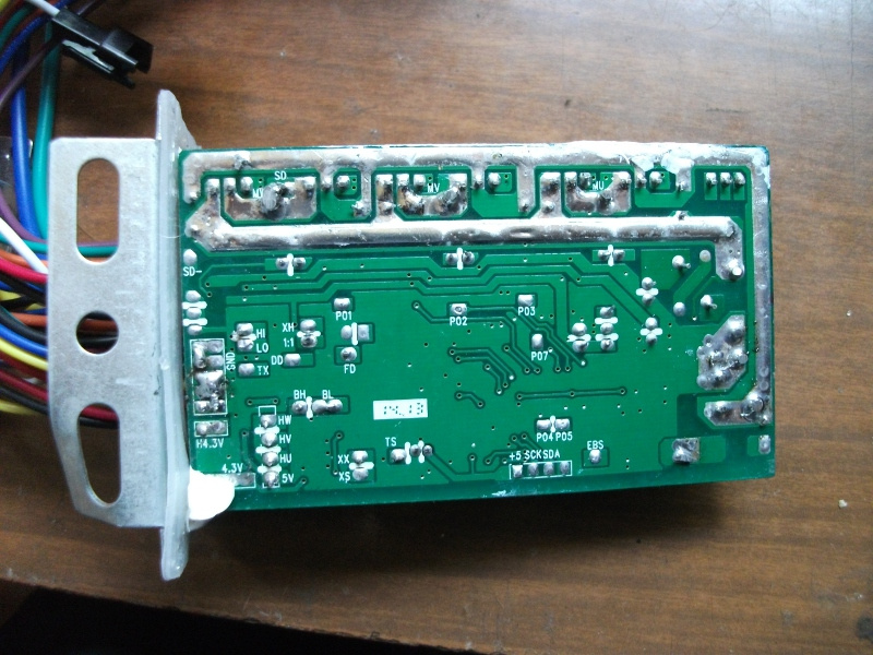
The card is marked VP350_G_V3.5.4. The power switches are S68N08R, these are N-channel MOSFET 68B, 80A, 6.5mΩ. There are unused pads, of which the following are interesting.
JTAG ICE - microcontroller in-circuit programming connector.
+ 5V - powered by the programmer with firmware.
SCK - external clocking.
SDA - data bus.
the unsigned point is earth.
EBS1 - as I understand it, a discrete input for the recovery function.
Also on the board there are unsealed jumpers marked 60V and EBS. Their purpose is obvious - switching the controller to a 60-volt battery and allowing regenerative braking. So, for just a thousand rubles, we have a very flexible and full-featured Infineon controller family.
Brushless motor controller (BLDC) purchased for the cheapest test. It is called Universal, universal, for the ability to work at different voltages, both with and without Hall sensors, automatically determine the phase and phase angle, learn and memorize the direction of rotation, and everything is possible in the field, it is enough to close two wiring. The controller is often positioned as a repair, they are replaced with a regular one in the event of a Hall sensor failure, if there are reasons to refrain from replacing them. The power rating of this variant is 350 W, but 18 amps at 48 volts DC is almost a kilowatt. If the controller does not like or spoil, I will redo it or even develop my own, but, looking ahead, I will say that the first trips are very pleased. It seems that the controller is necessary.
According to the good tradition of electric transport lovers, I will share the data in my specimen. Bracket bent on the mail, it's not scary. The presence of debris inside the block in the form of a couple of solder pieces is more serious, but we are craftsmen, so we’ll examine the device before we try it on, remove the debris, eliminate the seals and short-circuits if it is detected. I did not have them.
The sticker on the case-radiator reads as follows.
Brushless electric universal controller
voltage: 36V-48V power: 350w
Under voltage: 31V-41V
The phase Angle: 60 ° / 120 °
The controller has the following conclusions.
White connector - to the traction battery and anti-theft lock or switch.
Black thick wire - battery minus, power ground.
Red thick - plus batteries, power supply.
Red thin - VCCO - plus batteries through the lock (if available), power to the electronics.
The red connector is for charging.
Red - plus batteries, parallel to the red one.
Black - minus battery weight.
White connector - to the accelerator handle.
Black is mass.
Red - + 4.3V.
Green - analog input from the Hall sensor accelerator handle.
Black plug dad
White - weight
Black jack mom
White - XX - turns on self-learning mode when short to ground before turning on the power.
White connector - to the brake levers, with a short to ground (bicycle wiring option).
Orange - Brake LOW, discrete input, pulled through a resistor at + 5V.
Black is mass.
White connector - to the brake levers, in the case of the scooter wiring option.
Purple - Brake HI - is connected to the plus wire of the brake light, through the microswitches of the brake handles going to the battery plus.
In an electric bike, only one of these signals can be used, either Brake LOW or Brake HI.
Red connector - gearshift.
Blue - LO - includes the minimum speed when short to ground.
Black is mass.
Yellow - HI - includes the maximum speed when short to ground.
When the connector is not connected or the middle position of the switch, when LO and HI are disconnected from the ground, the average speed is enabled.
Green connector - to the speedometer.
Purple - SD1 - output from the phase winding of the motor and power switches. You can generate pulses and read them in a digital way, or you can convert the frequency into voltage by analogue. Of course, this will work only for a gearless motor.
Red connector - to the bike computer or anti-theft alarm.
Orange - VCCO - low current plus batteries.
Green - SD2 - parallel to SD1, output from the same phase.
Blue - output board called FD.
Black connector - to the PAS system pedal rotation sensor - pedal assistance.
Black is mass.
Red - + 4.3V.
Yellow - 1: 1.
There are, of course, three thick wires of the phases of the engine and a five-contact connector to the Hall sensors.
The card is marked VP350_G_V3.5.4. The power switches are S68N08R, these are N-channel MOSFET 68B, 80A, 6.5mΩ. There are unused pads, of which the following are interesting.
JTAG ICE - microcontroller in-circuit programming connector.
+ 5V - powered by the programmer with firmware.
SCK - external clocking.
SDA - data bus.
the unsigned point is earth.
EBS1 - as I understand it, a discrete input for the recovery function.
Also on the board there are unsealed jumpers marked 60V and EBS. Their purpose is obvious - switching the controller to a 60-volt battery and allowing regenerative braking. So, for just a thousand rubles, we have a very flexible and full-featured Infineon controller family.
Electrical Layout
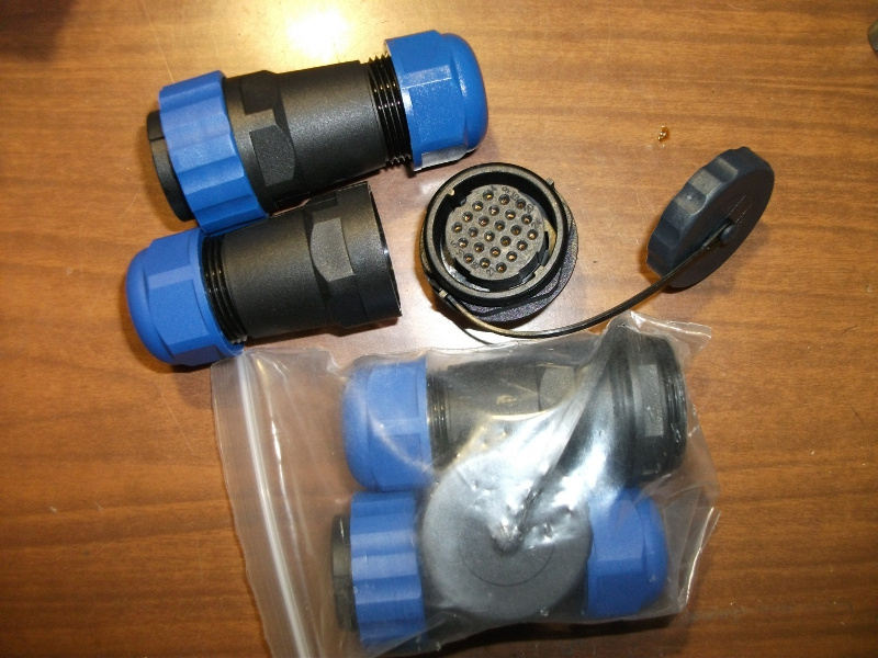
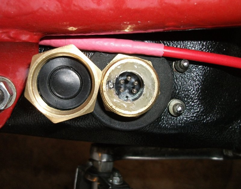
The motor-driven electroopedist is synchronous, has 3 phase wires, 3 wires from Hall sensors and earth wires and power wires of the latter. So that the wheel can be removed comfortably, we will use this waterproof connector, which we will fix on the shortened projection of the silencer fastening. At the 24-pin connector, 5 will occupy the Hall sensors, two phases will receive 6 each, and one of them 7. This will be enough for our currents. According to the mind, the assembled plug is filled with sealant, but the hot melt glue will come off with a subsequent treatment with silicone grease.
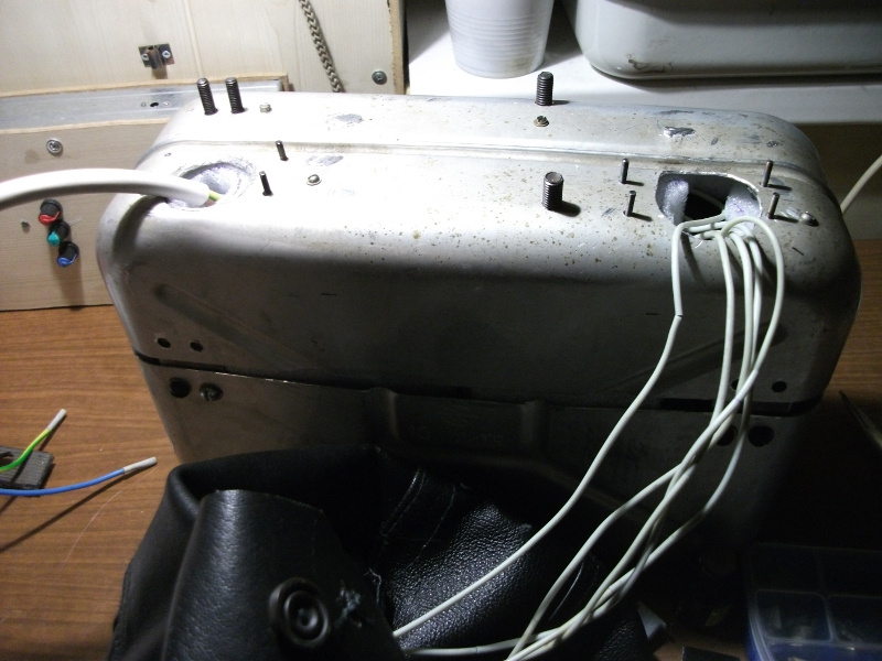
Electrical equipment Cherry decided to assemble inside a former gas tank. Some electric motorcycle builders rework the tank into a tool box or luggage compartment, but the Riga-12 has an instrumental compartment under the saddle, in the cavity of the frame where it would be possible to place the electronics, but it is difficult to maintain and it is undesirable to make slots and openings in the carrier spatial frame. In addition, the gas tank is just at the point where all the wires naturally converge. That's what happened. The U-shaped rubber profile for edging the tank and sealing the halves is a gasket for the timing cover of the VAZ 2108. I needed 4 of them - 2 for the frame and 2 for the joint.
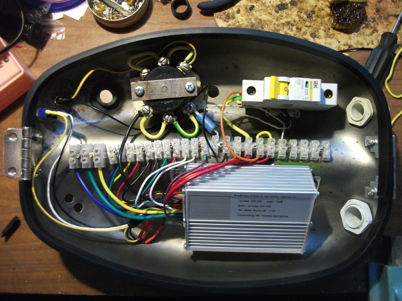
The unused wires from the controller are removed, all the standard connectors are also, instead of them the electrical terminals are taken. Plus, the battery is connected via a 25A circuit breaker, and a minus to ground is connected via a packet switch with a slightly modified mount. To prevent sparking of the mass switch, a chain of a resistor and a button is connected in parallel with it. Pressing the button before turning on the mass, we charge the controller smoothing capacitor. Although it was possible not to install this node with such a controller, the capacitor of a small capacity does not spark when powering the device. The switch is connected to the pins switching speeds. An anti-theft lock, speedometer, odometer, battery charge indicator will be placed on the upper lid of the former tank, and on the inside, fuses and power and control circuits for low-current circuits - light fixtures and an audible signal. I will devote to these modules the following publication. In the meantime, since we no longer have either a gas tank or a petrol engine, we will assemble our energy store — a traction battery.
Electrical equipment Cherry decided to assemble inside a former gas tank. Some electric motorcycle builders rework the tank into a tool box or luggage compartment, but the Riga-12 has an instrumental compartment under the saddle, in the cavity of the frame where it would be possible to place the electronics, but it is difficult to maintain and it is undesirable to make slots and openings in the carrier spatial frame. In addition, the gas tank is just at the point where all the wires naturally converge. That's what happened. The U-shaped rubber profile for edging the tank and sealing the halves is a gasket for the timing cover of the VAZ 2108. I needed 4 of them - 2 for the frame and 2 for the joint.
The unused wires from the controller are removed, all the standard connectors are also, instead of them the electrical terminals are taken. Plus, the battery is connected via a 25A circuit breaker, and a minus to ground is connected via a packet switch with a slightly modified mount. To prevent sparking of the mass switch, a chain of a resistor and a button is connected in parallel with it. Pressing the button before turning on the mass, we charge the controller smoothing capacitor. Although it was possible not to install this node with such a controller, the capacitor of a small capacity does not spark when powering the device. The switch is connected to the pins switching speeds. An anti-theft lock, speedometer, odometer, battery charge indicator will be placed on the upper lid of the former tank, and on the inside, fuses and power and control circuits for low-current circuits - light fixtures and an audible signal. I will devote to these modules the following publication. In the meantime, since we no longer have either a gas tank or a petrol engine, we will assemble our energy store — a traction battery.
Batteries
We did not make a reservation, it is really a battery, rechargeable acid battery. It is cumbersome and heavy, but fire and explosion-proof, cheap and reliable with proper handling. With regard to environmental cleanliness and health safety, again, with proper operation, a serviceable VRLA - valve-regulated lead battery - does not emit dangerous and harmful vapors and gases. That is what we use.
Common types of VRLA, or simply sealed batteries, are gel, with thickened electrolyte, and AGM, with a separator in the form of an absorbent layer of fiberglass. There are many modifications, specifications and prices are different, we will talk about this later. For now let's decide on the size of our batteries.
The battery case is a cut-down aluminum canister for drinking water. It will be located under the ridge of the frame, below the former gas tank, and it perfectly includes 4 batteries 12V 12A * h. The bottom row of two batteries is separated from the top by a partition of a suitable dielectric sheet material, the thickness of which must exceed the height of the terminals. I took a piece of MDF wall panel. The terminals are treated with silicone grease, which creates a water-repellent film in case water gets into the battery pack. In the bottom, (the unit will stand at an angle, for sealed batteries, this is the norm), small drainage holes are made to the edge of the aluminum case.
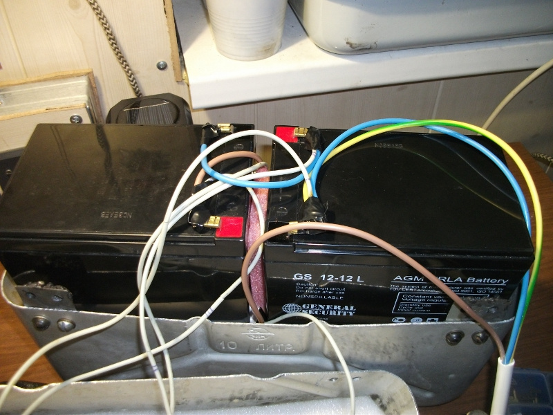
Oh God! The author of the article has installed cheap traction batteries for security alarms! On such you will not go far, and they will not last long! Yes, batteries were purchased intentionally from an almost lower price segment, for the sake of testing their capabilities in personal electric vehicles. If you don’t like it, I won’t be too lazy to remove and disassemble the battery case, and install specialized “green” 6-DZM-12 for electric scooters or other ones designed for a two-hour discharge without losing the output capacity. Then General Security GS-12-12L will start the service of lighting my house and powering the computer and soldering station in conditions of frequent interruptions in the power supply of the village.
The topic of lead-acid batteries, their characteristics and modes of operation will have to be returned. While we discuss the fastening of the batteries. A battery is a weighty and inert thing, and with a poor attachment it will beat about the nearest objects, as a result of which it will crack, with all the ensuing consequences, starting with electrolyte, which, although thickened, or, in our case, absorbed, but assumes the integrity of the battery can . In our container, the batteries are tightly clamped by spacers from the damping materials that were not prone to shrinkage, which would prevent their displacement during acceleration. The bottom row is on the strips of rubber. The top cover is worn with some force, fixing the batteries securely.
In addition to the power cable, from each of the jumpers between the poles of the battery removed the wires for a separate charge, for the sake of reliability clad in additional insulation PVC tube. And, finally, a case-bag, sewn from the existing good leatherette and generously treated with water-repellent agent and shoe polish, is put on top of the assembled wardrobe bag. , , , , , , . 4 , — , , .
, — 5- «», — 3/4 , . , , .
, 48 , 12 -. -. , , , . , , — . , , . . , .
Common types of VRLA, or simply sealed batteries, are gel, with thickened electrolyte, and AGM, with a separator in the form of an absorbent layer of fiberglass. There are many modifications, specifications and prices are different, we will talk about this later. For now let's decide on the size of our batteries.
The battery case is a cut-down aluminum canister for drinking water. It will be located under the ridge of the frame, below the former gas tank, and it perfectly includes 4 batteries 12V 12A * h. The bottom row of two batteries is separated from the top by a partition of a suitable dielectric sheet material, the thickness of which must exceed the height of the terminals. I took a piece of MDF wall panel. The terminals are treated with silicone grease, which creates a water-repellent film in case water gets into the battery pack. In the bottom, (the unit will stand at an angle, for sealed batteries, this is the norm), small drainage holes are made to the edge of the aluminum case.
Oh God! The author of the article has installed cheap traction batteries for security alarms! On such you will not go far, and they will not last long! Yes, batteries were purchased intentionally from an almost lower price segment, for the sake of testing their capabilities in personal electric vehicles. If you don’t like it, I won’t be too lazy to remove and disassemble the battery case, and install specialized “green” 6-DZM-12 for electric scooters or other ones designed for a two-hour discharge without losing the output capacity. Then General Security GS-12-12L will start the service of lighting my house and powering the computer and soldering station in conditions of frequent interruptions in the power supply of the village.
The topic of lead-acid batteries, their characteristics and modes of operation will have to be returned. While we discuss the fastening of the batteries. A battery is a weighty and inert thing, and with a poor attachment it will beat about the nearest objects, as a result of which it will crack, with all the ensuing consequences, starting with electrolyte, which, although thickened, or, in our case, absorbed, but assumes the integrity of the battery can . In our container, the batteries are tightly clamped by spacers from the damping materials that were not prone to shrinkage, which would prevent their displacement during acceleration. The bottom row is on the strips of rubber. The top cover is worn with some force, fixing the batteries securely.
In addition to the power cable, from each of the jumpers between the poles of the battery removed the wires for a separate charge, for the sake of reliability clad in additional insulation PVC tube. And, finally, a case-bag, sewn from the existing good leatherette and generously treated with water-repellent agent and shoe polish, is put on top of the assembled wardrobe bag. , , , , , , . 4 , — , , .
, — 5- «», — 3/4 , . , , .
, 48 , 12 -. -. , , , . , , — . , , . . , .
Governing bodies
, . . , , , . , , .
. «», — , , , . , , , . , , . , , .
, «» . . , , , , , , . . , - , , .

. , . , . , , .
. , . , — , . , .
, . . , , , . , , .
. «», — , , , . , , , . , , . , , .
, «» . . , , , , , , . . , - , , .
. , . , . , , .
. , . , — , . , .
, - «» -12 . , , , — , ! , , «», . , . . , !
, , , , . , . , , !
, , , , . , . , , !
Source: https://habr.com/ru/post/373545/
All Articles