Once again about receiving HF on RTL-SDR
Not just another cursory article on the modification of the tuner, but a detailed manual on how this is done, how it works, with a description of not only the finished design, but also the pitfalls, as well as just interesting accompanying facts.
The release of the RTL2832U chip for DVB-T digital television receivers did not promise any sensation, because Realtek was already somewhat late with its release. In 2010, the more progressive DVB-T2 standard with more efficient coding of information was already being introduced, so the new product did not attract much attention. For two years, cheap USB tuners at its base were used for their intended purpose, until at the beginning of 2012 some technical information about the operating modes of this chip leaked. It turned out that for receiving analog (FM) and digital (DAB) radio in the VHF band, this chip uses the principle of software decoding of a previously digitized frequency band from the air. Those. roughly speaking, it digitizes the high-frequency signal from the antenna input, and filtering of a specific carrier and its detection (allocation of useful information) from the received digital stream is left to the central processor. Obviously, this was done for reasons of economy, in the same way as at the time of sunset Dial-UP, extremely cheap “soft modems” received widespread distribution, which also represented only an advanced pair of DAC + ADC, and all signal processing was performed by CPU in thread with the highest priority.
')
It is this thirst for economy that predetermined the further fate of the majority of tuners assembled on the basis of the RTL2832U. The leak of information about the capabilities of the chip has the effect of a bombshell. No wonder, after all, all radio amateurs of the world received overnight a powerful radio monitoring tool. Receiver covering the range from Low-Band to remote VHF, not limited by the type of modulation, nor the sharpness of the setting, with the possibility of a panoramic viewing band of more than 3 MHz, and all this for $ 10! Well, let it be that work is possible only in a pair with a computer, but it is cheap and seemingly almost indistinguishable from a simple flash drive. For comparison, a classic scanning receiver with support for such a range of frequencies and modulation types (but without a panoramic view) costs about five hundred dollars and looks extremely suspicious in the hands of an ordinary person.
The RTL2832U-based receiver considered in this article is a classic SDR, which is why the people received the name RTL-SDR. Even Chinese online stores often sell these tuners under this name, completely forgetting to mention that in general this device was intended as a television tuner, and not a toy for radio amateurs.
A remarkable feature of almost any SDR is its omnivorousness, because even quite complex in the "iron" implementation coding methods (for example, single-band amplitude modulation - SSB) are easily processed programmatically and in practice for such a receiver there is no difference what to accept. As a demonstration of this feature, we can mention the curious development, which allows you to receive on such a tuner analog television. Yes, yes, these perverts forced the TV tuner to receive a TV signal! But the unusual thing here is that the tuner is kind of like, only for DVB-T, and the signal is still analog.
Also, with the help of this tuner, you can receive and decode GPS signals, conversations of subscribers of cellular networks (when encryption is turned off), or, say, “read” paging messages (where they are still running). For all this, there is either a standalone software, or plug-ins to universal "combines" like SDRSharp.
In short, a very successful toy turned out, but it does not happen that everything is all right at once. Monitoring the local VHF broadcast is certainly very interesting, but it would be much more interesting if it were possible to receive at lower frequencies. Indeed, only at frequencies less than 30 MHz, one can directly hear the signals from a transmitter located on the other side of the planet. Moreover, the advanced detection capabilities of various types of modulation are practically unclaimed in the range of ultrashort waves. Analog service connection, as a rule, is carried out using narrow-band frequency (NFM), and in the air band the usual amplitude modulation is used. The most energy-efficient and difficult to implement modulation method with a single sideband (SSB) on VHF is practically not used, but on short waves without it you can only listen to China Radio.
The problem of receiving short waves on the RTL-SDR has several solutions. The first is to feed the signal from the antenna directly to the input of the RTL2832U chip, bypassing the radio frequency module (usually represented by an R820T or R820T2 chip). This is called direct digitization (Direct Sampling, aka Q-branch or I-branch), and it is this method that is used in cheap do-it-yourself kits, widely represented in Chinese online stores.
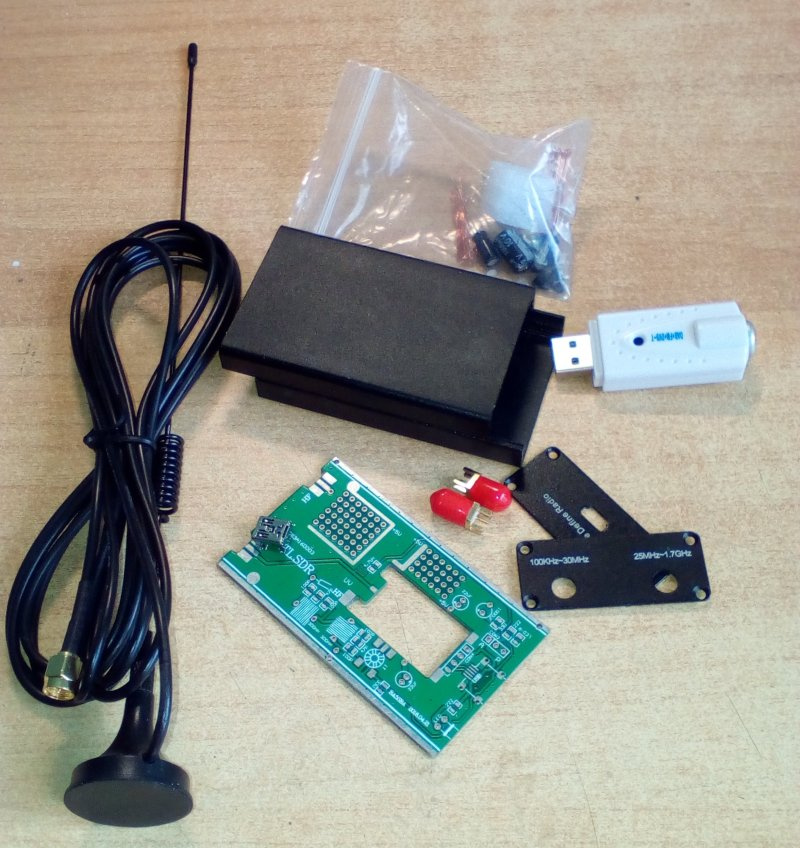
Such kits include a case, a TV tuner, a printed circuit board, a handful of discrete parts, and a very strange antenna. The tuner is supposed to be disassembled, unsoldered from its USB board and antenna connectors, and to solder what is left in the corresponding shaped cutout of the larger PCB. There are also discrete elements installed, it all twists into the body and the output is a pretty box no larger than a pack of cigarettes, theoretically capable of receiving signals in the range from zero to many hundreds of megahertz.
In practice, the direct digitization method, although it is extremely simple to implement, has too many drawbacks. The most important of them is the actual digitization of the signal only in the range up to 14400 kHz. It may receive higher frequencies, but this is already a side reception channel that interferes with the main one and which the main one interferes with. The second critical drawback is the rather low sensitivity of the short-wave receiver thus obtained. The RTL2832U input is not designed to handle the weak signals that come from an antenna. The real sensitivity is worse than several tens of microvolts, which is clearly not enough to receive long-range SSB stations, especially on an inefficient short antenna.
The low efficiency of the antenna can be compensated by increasing the sensitivity of the receiver. For example, coherent short-wave receivers usually have a sensitivity of 0.25 microvolts or better, so many dozens of microvolts of the “bare” RTL2832U are suitable only for receiving high-power broadcasting stations.
In addition to low sensitivity and problems with the operating range, the direct digitization scheme is inconvenient by the complexity of connecting additional wires to the terminals of the microcircuit. To make it really only a needle sting and under a strong increase. A firm hand is also vital, so many at this stage precisely ruined the tuner and sent the rest of the set in the closet.
And the influence of the connection on the work of the tuner in the “normal” mode, on VHF, is also of great concern. After all, even when reception at the HF is not needed, the winding of the matching transformer remains connected to the input of the RTL2832U, and therefore to the output of the radio-frequency module R820T connected to it, creating an additional parasitic load for it.
And even though these disadvantages are not limited to, I think what has already been said is enough to understand that collecting it in accordance with the manufacturer’s idea is not worth it. It is much better to use the kit as a basis for a more decent device for a similar purpose.
The second way to teach RTL-SDR to receive HF is to transfer the spectrum of 0-30 MHz to any other site with which the tuner can work without any modifications.
Such a transfer is called up-converting frequency and is performed using an auxiliary alternator and a circuit called a mixer. The essence of the mixer operation is as follows: when two signals with different frequencies are fed to its inputs, a third signal is generated at the output, the frequency of which is equal to the sum or difference of the input signals. In this case, the output signal repeats in itself all the amplitude and frequency oscillations of the input. Thus, if a signal received by an antenna in the range of 0-30 MHz is fed to one input, and not modulated alternating current from an auxiliary generator (local oscillator) with a frequency of, say, 100 MHz to the other, then we will get a full copy of the signal from the first input shifted 100 MHz up.
Varieties of frequency converters, there are a great many, all with their own advantages and disadvantages. Virtually any non-linear circuit can be used as a mixer: from a normal diode to complex symmetric multi-transistor circuits. But in our age of mass microelectronics it hardly makes sense to fence a complex mixer for a simple “whistle”, it is enough to use a ready-made microcircuit, besides combining the local oscillator and the mixer in one go.
Most of these converters offer the use of an SA602 chip, which has proven itself in communications equipment of almost all wavelength ranges. It is quite common, requires a minimum of “strapping”, and its capabilities more than cover our needs.
A completely similar chip can also be hidden in the case labeled NE602. There are also cheaper chips SA612 and NE612, which are slightly different in characteristics, but also quite suitable for frequency converter. The pinout and operating voltages of all four chips are the same, so they are completely interchangeable.
What else besides a local oscillator and a mixer is needed for a frequency converter? The last vital element of the circuit is the low-pass filter (LPF, also known as the Low-pass Filter). Its importance stems from the very principle of operation of the frequency converter. We remember that the mixer in the converter performs the addition and subtraction of the frequencies arriving at its inputs. And if with a frequency of 100 MHz LO at the second input we give a signal of 3.5 MHz, then we will be able to receive it with a tuner when tuned to 103.5 MHz. However, if we apply a signal with a frequency of 203.5 MHz to the second input, then the mixer will obligingly subtract the local oscillator frequency from it and again give us the same 103.5 MHz.
As a result, we will get double selection, and when tuning the tuner to 103.5 MHz, the reception will actually be conducted on two frequencies at once: 3.5 and 203.5 MHz. The parasitic reception channel at a frequency of 203.5 MHz is called specular and it is from it that one has to get rid of the pre-filtering of the input signal.
To suppress unwanted reception channels, the signal from the antenna must be cleared of all frequencies outside the range of interest before being fed to the mixer input. Indeed, if the difference between the main and mirror channels is equal to the double frequency of the local oscillator, cutting off everything that has a frequency above 30 MHz (the conditional boundary between short and ultrashort waves) allows us to cut off the mirror channel with a large margin.
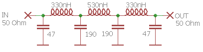
This cut and deals with a low pass filter. We will not dwell on the principle of its action, especially since it is obvious to anyone who knows what inductive and capacitive resistance is. The main thing for us is that it is very simple to implement and, in spite of its analog-high-frequency essence, does not need any adjustment when properly manufactured. The scheme of the seventh-order low-pass filter with a cut-off frequency of 30 MHz is as follows:
In principle, with three vital elements were determined, and if you make the frequency converter according to the standard scheme of the datasheet, then it will already work. However, this scheme has another non-obvious drawback, which will significantly degrade the characteristics of the device.
The input of the selected chip mixer has a resistance of about 1500 Ohms, and the quarter-wave antenna described above is only 50 Ohms or less. At first glance it seems that nothing terrible, because from the “power” point of view it is important that the consumer (the input of the chip) has a higher internal resistance than the source (antenna), and in this case this condition is met. But from a “signaling” point of view, this ratio means that the consumer does not take all the power from the source. And where the consumer does not take everything that is offered to him, the signal always passes with losses.
Many novice designers generally do not pay attention to the coordination of resistances precisely because they are guided by a "force" approach. After all, the resistance of a light bulb is many orders of magnitude higher than the output resistance of the nearest transformer substation, and nothing, the bulb is lit, the substation does not explode. The mistake here is that before the light bulb there is no task to “suck out” all the energy from the substation, its function is to take exactly as much as it needs. At the same time, in the signal circuits, any shortage and overshooting lead to the fact that some of the energy simply does not reach from the source to the consumer and as a result, the signal is weakened.
The most correct solution to the problem of matching the low output impedance of the antenna with the high input impedance of the mixer is a transformer. It can exactly match the resistance, simultaneously raising the voltage of the input signal several times, without consuming a milliampere of current. However, a transformer operating in the range from fractions up to 30 MHz, not burdened with a mass of parasitic resonances, and not contributing to a signal of large losses, is rather difficult to manufacture. This does not mean that it is impossible, but within the framework of the described device it is not a fact that the efforts expended on its manufacture will be justified. Therefore, instead of a transformer, it was decided to use a matching LC circuit, which is part of the input low-pass filter. This coordination is certainly worse than a quality transformer of resistances, but it is “free” within the framework of the chosen scheme, because it is realized only by changing the nominal values of the elements already existing in the scheme.
The second point of the circuit where the impedance matching is required is the mixer output. Here the situation is even worse than at the input, because a high-resistance (the same 1.5 ohm) source must be connected to a low-resistance consumer (the tuner input has a standard “television” impedance of 75 ohms).
In principle, here is the same place as a transformer or, in extreme cases, a matching LC filter.But the manufacture of a transformer, as mentioned above, is not worth the effort, and the matching filter, firstly, has too “humped” amplitude-frequency response, and secondly, is redundant in terms of the need to filter something in this point scheme. In general, I decided to use an active matching cascade. Although it requires some energy for its work, but it allows you to get almost perfect reduction of resistance in any reasonable range.

In this circuit, the load of the transistor is not included in the collector circuit, as is done in the usual amplifying stage, but in the emitter circuit. As a result, from the point of view of the input signal, the collector is grounded (via a power source), and the circuit is called a cascade with a common collector. Such a cascade does not provide voltage amplification, but it does allow to add “current power” to a high-resistance signal source, or, in other words, to reduce its output impedance.
In our case, the cascade is loaded with a 75 Ohm resistor, which provides perfect matching with the tuner input, and the high linearity of the repeater allows us to easily cover the entire range of 0-30 MHz without losing a decibel. The only "but": it is desirable to choose a transistor for this cascade with a large current transfer ratio, it is better if it is 200 units or higher. Most instances of the transistor 2N2222A satisfy this condition (if not rejection, of course), but still it is better to double-check with at least a simple Chinese multimeter.
, «» . , , . , -.
, . «» .
, , . . ( ), . , . , : .

Unfortunately, all locally available imported reed relays appeared to have one closing contact, which did not allow switching signal sources. There was no wish to fence two separate relays, so I had to drop the RES55A relay out of some measuring device from the old Soviet board. This is a reed switch with one switching contact, quite suitable for switching a receiving antenna in the range of short waves.
5 55 03xx, 08xx, 11xx, 16xx ( 4.569.600-03, 4.569.600-08, 4.569.600-11 4.569.600-16 ). 6- 02xx, 07xx, 15xx (4.569.600-02, 4.569.600-07, 4.569.600-15). 57 110 .
, , , . , , .
:

In it, we see the already familiar low-pass filter, the actual chip of the frequency converter with piping, the output matching stage on the transistor, and the switching relay. Switching the ANT tuner input to the conversion output is done automatically at the same time as powering the circuit.
The assignment of resistor R1 and capacitor C1 may not seem very understandable, but if we recall that a good shortwave antenna can reach a length of several tens of meters, the idea arises of atmospheric electricity. No, it will not save anything from a direct lightning strike to the antenna, but it is quite possible to secure oneself from static and induced impulse discharge. Resistor R1 (preferably with a power of 1 Watt) simply opens up static electricity to the ground, and capacitor C1 (this should be a high-voltage ceramic capacitor with a voltage of at least 1 kV) prevents this electricity from entering the input of the microcircuit. In other matters, if the reception is planned only for a shortened antenna, then the resistor can not be installed at all, and the capacitor can be replaced with a jumper (or an ordinary one,non-high-voltage ceramic capacitor of the same capacity).
D1, , , . . , , , . 10 .
. 40 . :
, .

An ideal transfer frequency would be 120-125 MHz. Given its value, the entire section of 0–30 MHz is transferred to a relatively “quiet” wave band, where there are no broadcast transmitters.
. , . .
– , . , «» , . , , . .
Experiments with 14-25 MHz quartz, dropped from the old computer junk and purchased in China, have shown that most of them are unsuitable for work even on the third overtone. Apparently their plates are cut out in such a way that their activity on the harmonics is extremely low, and the generator is either not excited at all, or rolls onto the fundamental frequency without looking at the suppressor element. Of course, with due persistence you can find quartz, which will work on the seventh harmonic and will give a frequency of more than 100 MHz, but this was not so easy, and the complexity of setting up such a generator is already beyond the simplest design. Therefore, it was decided to compromise and use the transfer to a frequency of about 50 MHz. The resulting 50-80 MHz operating section is also superimposed on the old VHF broadcasting range of 66-74 MHz,however, today in most places it is actually abandoned due to the low prevalence of radio receivers supporting it.
A separate problem is the first three channels of television broadcasting, which also fall into this range and can often cause interference. But in cities, broadcasting on these channels today is quite rare, and in rural areas, the distance to the transmitter usually allows you not to worry about interference.
In any case, if there is interference on the HF, it is worth trying to disconnect the VHF antenna from the device, which through the capacity of the relay and installation always has some connection to the tuner input.
, , , , , .
, “49.475”, . L4/C8, . 16.5 .
L4 C8 “45.000” “55.000”, “15.000”-“18.500”. , L4 / C8 , ( LC- 30 ). «» , , 40 , L4 , .

«» . -, SSB 100 , . -, RTL-SDR , .
:


archive with files of the scheme and the printed circuit board
The board is double-sided, but this is primarily due to the installation of connectors, the entire frequency converter circuit is divorced on the lower layer, and the top one, since it is still there, is used as a screen.
If you look closely, you will notice that the wiring does not exactly match the pattern. Firstly, capacitors C4 and C5 are connected by a single output not to the “ground”, as in the circuit diagram, but to the power supply bus. This is done to simplify wiring, but this inclusion does not affect the operation of the filter, because the AC power bus has multiple contacts with a common conductor through blocking capacitors. The number of blocking capacitors, duplicating C14, also increased compared with the scheme. In fact, they are installed wherever there was space and failed tires for them. A large number of them also contributes to increasing the stability of the operation of any high-frequency electronic device.
Another missing element on the diagram is a tin screen around all discrete parts that make up a quartz oscillator. Due to the fact that the output of the mixer is connected to a rather sensitive device in the form of a TV tuner, it is necessary to minimize the leakage of the local oscillator signal, to which the tuner is as sensitive as to the useful signal. Contact pads for mounting the screen surround the quartz Q1, coil L4, capacitors C7-C9, and all of them are connected to ground. The metal case of quartz is also grounded to this screen in its upper part with a wire jumper.
You can solder the screen either on wire racks, or by threading thin tin “tongues” left in the holes of the board when it is cut.
Filter coils L1, L2 and L3 are frameless, they are wound with an insulated winding wire of about 0.5 mm (included in the set) on a disc with a diameter of 7 mm. They contain 7, 9 and 13 turns, respectively. In principle, in this place you can use ready-made output inductances of the required nominal values, but I strongly recommend to wind them yourself. It is not difficult at all, and the final quality of the filter will be much higher due to the lower parasitic capacitance and higher quality of home-made coils.
In my motherboard, the tuner is installed not horizontally, as in the original, but vertically to save space. The cut-out of the shape allows you to solder it with a common conductor to the “ground” of the main board on both sides, and the power and data lines from the USB connector need to be connected to it with short flexible conductors. The position of all connectors and LEDs is saved so that the original case can be used with minimal modifications. The only difference is the use of a dual two-color LED with a common cathode, which allows you to display both modes of operation of the device. The hole for the mode selector must be drilled independently in the same side rail, which has a notch for USB and an LED.

The mode selector switch is a conventional miniature toggle switch or a latching button with one switching contact that in one position supplies power to the entire circuit, and in the other to only one half of the indicator LED. All connections of the switch with the board are made of flexible insulated wire.
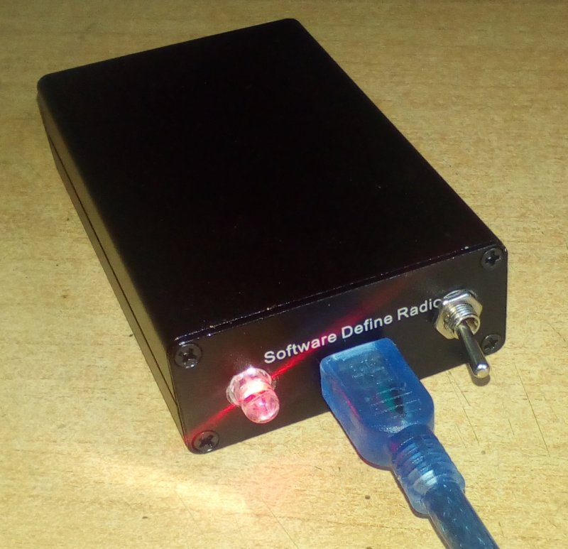
The device after assembly (see KDPV) outwardly differs little from what would have happened when the original kit was mounted, however this is already a device of a completely different class.
As an example, I will use the popular product SDRSharp, which can work with frequency transfer. The exact frequency of the crystal oscillator must be entered in the Shift field with a negative sign. I will not dwell on the intricacies of setting up a program for working in the range of short waves, because this good is on the network and so in bulk. But I can not keep silent about one feature, about which not everyone knows.
I described the method for determining the frequency of quartz above, but it is necessary to take into account the fact that each copy of the tuner has some individual tuning error. When working with broadband signals of TV- and FM-broadcasts, such an error does not affect the performance in any way, however, when receiving narrow-band modulation (especially SSB and CW), it often exceeds the channel width. Therefore, before measuring the exact frequency of quartz, you need to calibrate the tuner itself.
For calibration, you need to take the tuner any signal whose frequency is precisely known. Broadcast transmitters are usually stabilized very carefully, so any FM station can be used as a reference. But the signal of the broadcasting VHF transmitter is broadband enough, while to calibrate the tuner, the carrier frequency should be selected from the whole spectrum. The easiest way to do this is when there is no modulation, i.e. when transmitting silence. At this moment, the emission spectrum of a stereo transmitter takes the form of a trident or a more complex figure with several narrow peaks, the central one of which corresponds to the carrier frequency.
Catching a moment of silence can be tricky, but the SDRSharp feature helps in this case, which allows you to record a “raw” signal from the air onto the disc and then play it cyclically exactly as if the real tuner were working. If at least one moment of silence falls into the record, then returning to it again and again, you can fix the exact frequency of the carrier.

The real frequency of the transmitter can be determined by the nearest value multiple of 100 kHz. In the screenshot, the tuner receives a signal of 95,998,350 Hz, although it is obvious that the broadcasting station is operating at 96,000,000 Hz. To calibrate, you need to change the “ppm” parameter of the settings so that the central peak is located symmetrically around the scale mark corresponding to the actual frequency of the signal.

The approximate PPM value can be calculated by the formula:
where: f is the real frequency of the transmitter; F - tuner tuning frequency. The calculated value (in my case it is equal to 17) can be used as a starting point, and the exact value obtained when viewing more narrowband spectra is likely to be slightly different.
Other signals can be used as a reference if it is certain that they have sufficient frequency setting accuracy. Do not strongly trust the transmitters of connected VHF radio stations (especially cheap Chinese “bling”), because for them, an error of several hundred Hz is completely acceptable and completely imperceptible at work. The transmitters of "serious" services, for example, the control tower of the nearest airport, are likely to be fairly accurate, but you should not blindly believe the frequencies of the "boards".

Also, the tuning temperature is slightly affected by the temperature of the tuner, so it is advisable to start the calibration after 10–15 minutes warm-up in the operating mode.
After starting the converter, the calibration can be refined by the signals of short-wave broadcasting stations, whose spectrum is much more suitable for this. However, for the reason that the HF tuning can be influenced by both the calibration of the tuner itself and the accuracy of entering the local oscillator frequency, it will be more difficult to determine which of them to correct. For example, if by adjusting the frequency of the local oscillator in the Shift field, it was possible to combine the setting with the real transmitter frequency in one band, but the match is broken on the other bands, then this is a matter of calibrating the tuner. If all stations are shifted by the same amount, then it is necessary to correct the Shift field.
Actually, everything. Good luck to you, 73!
A bit of history
The release of the RTL2832U chip for DVB-T digital television receivers did not promise any sensation, because Realtek was already somewhat late with its release. In 2010, the more progressive DVB-T2 standard with more efficient coding of information was already being introduced, so the new product did not attract much attention. For two years, cheap USB tuners at its base were used for their intended purpose, until at the beginning of 2012 some technical information about the operating modes of this chip leaked. It turned out that for receiving analog (FM) and digital (DAB) radio in the VHF band, this chip uses the principle of software decoding of a previously digitized frequency band from the air. Those. roughly speaking, it digitizes the high-frequency signal from the antenna input, and filtering of a specific carrier and its detection (allocation of useful information) from the received digital stream is left to the central processor. Obviously, this was done for reasons of economy, in the same way as at the time of sunset Dial-UP, extremely cheap “soft modems” received widespread distribution, which also represented only an advanced pair of DAC + ADC, and all signal processing was performed by CPU in thread with the highest priority.
')
The high priority of the signal processing flow with a frequency band of just over 3 kHz led to a noticeable slowdown of the PC at that time. Today's systems behave in a comparable manner, processing 1000 times more information.
It is this thirst for economy that predetermined the further fate of the majority of tuners assembled on the basis of the RTL2832U. The leak of information about the capabilities of the chip has the effect of a bombshell. No wonder, after all, all radio amateurs of the world received overnight a powerful radio monitoring tool. Receiver covering the range from Low-Band to remote VHF, not limited by the type of modulation, nor the sharpness of the setting, with the possibility of a panoramic viewing band of more than 3 MHz, and all this for $ 10! Well, let it be that work is possible only in a pair with a computer, but it is cheap and seemingly almost indistinguishable from a simple flash drive. For comparison, a classic scanning receiver with support for such a range of frequencies and modulation types (but without a panoramic view) costs about five hundred dollars and looks extremely suspicious in the hands of an ordinary person.
The RTL2832U-based receiver considered in this article is a classic SDR, which is why the people received the name RTL-SDR. Even Chinese online stores often sell these tuners under this name, completely forgetting to mention that in general this device was intended as a television tuner, and not a toy for radio amateurs.
Software Defined Radio is a device for receiving and / or transmitting radio signals, built on the basis of digital signal processing by a computer processor. It differs from the classical “analog” principle precisely in that the signal at the earliest possible stages (in the case of a receiver) is converted into a digital form and is subsequently processed by the processor. This allows you to get rid of the mass of analog circuit elements, often expensive and / or requiring fine tuning. In the case of an SDR transmitter, the signal to the last exists in digital form and passes the DAC at the very end of its formation. In addition to analogue radio and SDR, there is also a large class of DSP radio, which is much like SDR, but not just a program, but a specialized DSP chip (Digital Signal Processor) is responsible for digital processing. Such a digital signal processor implements all or part of signal processing algorithms at the logic level, rather than the program code, which makes it more economical and efficient, though less flexible, compared to SDR. In practice, it is often difficult to draw a clear line between SDR and DSP.
A remarkable feature of almost any SDR is its omnivorousness, because even quite complex in the "iron" implementation coding methods (for example, single-band amplitude modulation - SSB) are easily processed programmatically and in practice for such a receiver there is no difference what to accept. As a demonstration of this feature, we can mention the curious development, which allows you to receive on such a tuner analog television. Yes, yes, these perverts forced the TV tuner to receive a TV signal! But the unusual thing here is that the tuner is kind of like, only for DVB-T, and the signal is still analog.
Unfortunately, the receiver of an analog television signal is not very complete, and nothing can be done about it. The problem is that the image signal in PAL or SECAM systems with a decomposition of 625 lines takes up to 6.5 MHz on the air, while the RTL2832U in SDR mode is able to digitize a maximum of 3.2 MHz at one time. As a result, due to the limitations of the available frequency band, the image is received with significantly reduced horizontal detail, and the soundtrack (for transmission of which a separate carrier is used aside from the image signal) is not accepted at all.
Also, with the help of this tuner, you can receive and decode GPS signals, conversations of subscribers of cellular networks (when encryption is turned off), or, say, “read” paging messages (where they are still running). For all this, there is either a standalone software, or plug-ins to universal "combines" like SDRSharp.
So what with short waves?
In short, a very successful toy turned out, but it does not happen that everything is all right at once. Monitoring the local VHF broadcast is certainly very interesting, but it would be much more interesting if it were possible to receive at lower frequencies. Indeed, only at frequencies less than 30 MHz, one can directly hear the signals from a transmitter located on the other side of the planet. Moreover, the advanced detection capabilities of various types of modulation are practically unclaimed in the range of ultrashort waves. Analog service connection, as a rule, is carried out using narrow-band frequency (NFM), and in the air band the usual amplitude modulation is used. The most energy-efficient and difficult to implement modulation method with a single sideband (SSB) on VHF is practically not used, but on short waves without it you can only listen to China Radio.
The problem of receiving short waves on the RTL-SDR has several solutions. The first is to feed the signal from the antenna directly to the input of the RTL2832U chip, bypassing the radio frequency module (usually represented by an R820T or R820T2 chip). This is called direct digitization (Direct Sampling, aka Q-branch or I-branch), and it is this method that is used in cheap do-it-yourself kits, widely represented in Chinese online stores.
Such kits include a case, a TV tuner, a printed circuit board, a handful of discrete parts, and a very strange antenna. The tuner is supposed to be disassembled, unsoldered from its USB board and antenna connectors, and to solder what is left in the corresponding shaped cutout of the larger PCB. There are also discrete elements installed, it all twists into the body and the output is a pretty box no larger than a pack of cigarettes, theoretically capable of receiving signals in the range from zero to many hundreds of megahertz.
In practice, the direct digitization method, although it is extremely simple to implement, has too many drawbacks. The most important of them is the actual digitization of the signal only in the range up to 14400 kHz. It may receive higher frequencies, but this is already a side reception channel that interferes with the main one and which the main one interferes with. The second critical drawback is the rather low sensitivity of the short-wave receiver thus obtained. The RTL2832U input is not designed to handle the weak signals that come from an antenna. The real sensitivity is worse than several tens of microvolts, which is clearly not enough to receive long-range SSB stations, especially on an inefficient short antenna.
Antennas are a separate very large topic on which thousands of serious works are written. In the philistine circles there is an opinion that the longer the antenna is, the better it works, but in most cases this is not at all the case. The best result comes from an antenna tuned to resonance. And the simplest way to achieve resonance is to choose the right size. An effective wire antenna should have a length approximately equal to a quarter of the wavelength of the receiving station. For example, to receive a signal at frequencies in the region of 3.5 MHz (a wavelength of about 85 meters) is best to be a 21-meter wire. You should not measure up to centimeters, because the resonance curve is still rather flat. It is very detrimental to the quality of the antenna affects any parallel to it a conductive object, including the ground. Therefore, the wire must be vertical or inclined and not located at acute angles to close metal or concrete structures. If it is impossible to build a full-sized antenna, it is allowed to roll the wire into a three-five-meter spiral (but its real length still approximately corresponds to a quarter of the wavelength). Just do not forget that in the case of using a quarter-wave antenna, the external contact of the antenna input of the receiver must be grounded or connected to a wire counterweight of the same length.
The low efficiency of the antenna can be compensated by increasing the sensitivity of the receiver. For example, coherent short-wave receivers usually have a sensitivity of 0.25 microvolts or better, so many dozens of microvolts of the “bare” RTL2832U are suitable only for receiving high-power broadcasting stations.
By the way, the antenna from the kit is designed for a cellular modem, which is directly written on it. On short waves, it works almost nothing, and what made the Chinese manufacturer to put it into a set at all is a great mystery.
In addition to low sensitivity and problems with the operating range, the direct digitization scheme is inconvenient by the complexity of connecting additional wires to the terminals of the microcircuit. To make it really only a needle sting and under a strong increase. A firm hand is also vital, so many at this stage precisely ruined the tuner and sent the rest of the set in the closet.
And the influence of the connection on the work of the tuner in the “normal” mode, on VHF, is also of great concern. After all, even when reception at the HF is not needed, the winding of the matching transformer remains connected to the input of the RTL2832U, and therefore to the output of the radio-frequency module R820T connected to it, creating an additional parasitic load for it.
And even though these disadvantages are not limited to, I think what has already been said is enough to understand that collecting it in accordance with the manufacturer’s idea is not worth it. It is much better to use the kit as a basis for a more decent device for a similar purpose.
Frequency conversion
The second way to teach RTL-SDR to receive HF is to transfer the spectrum of 0-30 MHz to any other site with which the tuner can work without any modifications.
Such a transfer is called up-converting frequency and is performed using an auxiliary alternator and a circuit called a mixer. The essence of the mixer operation is as follows: when two signals with different frequencies are fed to its inputs, a third signal is generated at the output, the frequency of which is equal to the sum or difference of the input signals. In this case, the output signal repeats in itself all the amplitude and frequency oscillations of the input. Thus, if a signal received by an antenna in the range of 0-30 MHz is fed to one input, and not modulated alternating current from an auxiliary generator (local oscillator) with a frequency of, say, 100 MHz to the other, then we will get a full copy of the signal from the first input shifted 100 MHz up.
As a rule, the mixer produces both the addition and subtraction of frequencies. Therefore, when applying to its inputs a useful signal with a frequency of 3.5 MHz and a signal of a local oscillator of 100 MHz, we will have two mirror signals with frequencies of 103.5 and 96.5 MHz at the output. In conventional analog circuits, unnecessary frequencies are disposed of by filters, but in our case this is not necessary. It is enough just not to tune the tuner to frequencies below 100 MHz and we can assume that they do not exist. Moreover, RTL-SDR software configured to work with such a transfer will simply not allow tuning into a parasitic conversion product.
Varieties of frequency converters, there are a great many, all with their own advantages and disadvantages. Virtually any non-linear circuit can be used as a mixer: from a normal diode to complex symmetric multi-transistor circuits. But in our age of mass microelectronics it hardly makes sense to fence a complex mixer for a simple “whistle”, it is enough to use a ready-made microcircuit, besides combining the local oscillator and the mixer in one go.
Most of these converters offer the use of an SA602 chip, which has proven itself in communications equipment of almost all wavelength ranges. It is quite common, requires a minimum of “strapping”, and its capabilities more than cover our needs.
A completely similar chip can also be hidden in the case labeled NE602. There are also cheaper chips SA612 and NE612, which are slightly different in characteristics, but also quite suitable for frequency converter. The pinout and operating voltages of all four chips are the same, so they are completely interchangeable.
The only theoretically noticeable difference in this case between SA612 / NE612 and SA602 / NE602 chips is their smaller gain, 14 dB versus 18. However, in practice, in the scheme below, I could not detect by ear any difference between them, so you can safely use the one that comes first.
What else besides a local oscillator and a mixer is needed for a frequency converter? The last vital element of the circuit is the low-pass filter (LPF, also known as the Low-pass Filter). Its importance stems from the very principle of operation of the frequency converter. We remember that the mixer in the converter performs the addition and subtraction of the frequencies arriving at its inputs. And if with a frequency of 100 MHz LO at the second input we give a signal of 3.5 MHz, then we will be able to receive it with a tuner when tuned to 103.5 MHz. However, if we apply a signal with a frequency of 203.5 MHz to the second input, then the mixer will obligingly subtract the local oscillator frequency from it and again give us the same 103.5 MHz.
As a result, we will get double selection, and when tuning the tuner to 103.5 MHz, the reception will actually be conducted on two frequencies at once: 3.5 and 203.5 MHz. The parasitic reception channel at a frequency of 203.5 MHz is called specular and it is from it that one has to get rid of the pre-filtering of the input signal.
The given example is the simplest and relatively “harmless” case. In practice, the parasitic reception channels always turn out to be much larger, because due to the imperfection of the real mixer elements and the cross-influence of different parts of the circuit, the frequencies resulting from the conversion can again get to the input of the mixer. As a result, instead of two mirror channels, the receiver already receives a whole range of frequencies. Of course, its sensitivity on such high-order parasitic channels turns out to be significantly lower than on two “fundamental” channels, but, nevertheless, if one of them has a powerful signal or interference, it can cause a lot of problems.
To suppress unwanted reception channels, the signal from the antenna must be cleared of all frequencies outside the range of interest before being fed to the mixer input. Indeed, if the difference between the main and mirror channels is equal to the double frequency of the local oscillator, cutting off everything that has a frequency above 30 MHz (the conditional boundary between short and ultrashort waves) allows us to cut off the mirror channel with a large margin.
This cut and deals with a low pass filter. We will not dwell on the principle of its action, especially since it is obvious to anyone who knows what inductive and capacitive resistance is. The main thing for us is that it is very simple to implement and, in spite of its analog-high-frequency essence, does not need any adjustment when properly manufactured. The scheme of the seventh-order low-pass filter with a cut-off frequency of 30 MHz is as follows:
There is some confusion in the naming of low and high pass filters in Russian literature. Some authors are guided by this logic: “a filter should be called a low-pass filter if it filters out (i.e., suppresses) low frequencies”. Others, on the contrary, think so: “if a filter clears (i.e., on the contrary, leaves) low frequencies, then it should be called a low-pass filter”. As a result, in different sources, LPF (or HPF) implies completely opposite concepts. To eliminate confusion, I propose to recall English terms that do not allow ambiguity. A filter that passes low (i.e., suppresses high) frequencies is called a Low-pass Filter. Reverse to him, respectively, - High-pass Filter. All unequivocally and no confusion. And if you translate a key word in English and impose it on a Russian term, it turns out that Low- Pass Filter is a low- pass filter, i.e. LPF At the same time, High- Pass Filter is a high- pass filter, highpass filter.
In principle, with three vital elements were determined, and if you make the frequency converter according to the standard scheme of the datasheet, then it will already work. However, this scheme has another non-obvious drawback, which will significantly degrade the characteristics of the device.
Matching resistance
The input of the selected chip mixer has a resistance of about 1500 Ohms, and the quarter-wave antenna described above is only 50 Ohms or less. At first glance it seems that nothing terrible, because from the “power” point of view it is important that the consumer (the input of the chip) has a higher internal resistance than the source (antenna), and in this case this condition is met. But from a “signaling” point of view, this ratio means that the consumer does not take all the power from the source. And where the consumer does not take everything that is offered to him, the signal always passes with losses.
Many novice designers generally do not pay attention to the coordination of resistances precisely because they are guided by a "force" approach. After all, the resistance of a light bulb is many orders of magnitude higher than the output resistance of the nearest transformer substation, and nothing, the bulb is lit, the substation does not explode. The mistake here is that before the light bulb there is no task to “suck out” all the energy from the substation, its function is to take exactly as much as it needs. At the same time, in the signal circuits, any shortage and overshooting lead to the fact that some of the energy simply does not reach from the source to the consumer and as a result, the signal is weakened.
For a better understanding of the meaning of the coordination of resistances, in my opinion, the analogy from the world of mechanics is most suitable. Connecting a high-impedance load to a low-impedance source is like lifting a matchbox to a great height with a slow, multi-ton crane. Yes, the boxes will be raised without problems, but it will be spent thousands of times more energy and time than necessary. If we transform the power of the crane in such a way that the torque of the winch decreased to the minimum required for lifting the box and its rotational speed increased proportionally, then the boxes would fly into the stratosphere in a couple of seconds. Here and in electrical circuits occur similar phenomena, but instead of rotational speed — voltage, instead of torque — current, and the role of a reducer is played by a matching circuit.
The most correct solution to the problem of matching the low output impedance of the antenna with the high input impedance of the mixer is a transformer. It can exactly match the resistance, simultaneously raising the voltage of the input signal several times, without consuming a milliampere of current. However, a transformer operating in the range from fractions up to 30 MHz, not burdened with a mass of parasitic resonances, and not contributing to a signal of large losses, is rather difficult to manufacture. This does not mean that it is impossible, but within the framework of the described device it is not a fact that the efforts expended on its manufacture will be justified. Therefore, instead of a transformer, it was decided to use a matching LC circuit, which is part of the input low-pass filter. This coordination is certainly worse than a quality transformer of resistances, but it is “free” within the framework of the chosen scheme, because it is realized only by changing the nominal values of the elements already existing in the scheme.
The second point of the circuit where the impedance matching is required is the mixer output. Here the situation is even worse than at the input, because a high-resistance (the same 1.5 ohm) source must be connected to a low-resistance consumer (the tuner input has a standard “television” impedance of 75 ohms).
Again an example from mechanics. Imagine an electric motor with a nominal speed of, say, 3000 revolutions per minute, and an elevator. Suppose that the engine power is exactly the power required to raise the cab. However, if we directly connect the shaft of such an engine and an elevator winch, nothing good will come of it. The motor shaft tends to spin too fast, but it provides too little torque for the elevator car to move in normal mode. Yes, probably such an elevator will still be able to work. With a strong overload of the engine and / or "space" speed of movement of the cabin after acceleration. In order for our elevator to work normally, the engine also needs a gearbox, which will reduce the rotational speed and at the same time increase the torque. And this situation is worse than the previous one because not only the energy of the source is not optimally used here, but also the mode of its operation is disrupted due to excessive load.
In principle, here is the same place as a transformer or, in extreme cases, a matching LC filter.But the manufacture of a transformer, as mentioned above, is not worth the effort, and the matching filter, firstly, has too “humped” amplitude-frequency response, and secondly, is redundant in terms of the need to filter something in this point scheme. In general, I decided to use an active matching cascade. Although it requires some energy for its work, but it allows you to get almost perfect reduction of resistance in any reasonable range.
In this circuit, the load of the transistor is not included in the collector circuit, as is done in the usual amplifying stage, but in the emitter circuit. As a result, from the point of view of the input signal, the collector is grounded (via a power source), and the circuit is called a cascade with a common collector. Such a cascade does not provide voltage amplification, but it does allow to add “current power” to a high-resistance signal source, or, in other words, to reduce its output impedance.
– , . , , 100%. , . . , , . , , , , , , .
In our case, the cascade is loaded with a 75 Ohm resistor, which provides perfect matching with the tuner input, and the high linearity of the repeater allows us to easily cover the entire range of 0-30 MHz without losing a decibel. The only "but": it is desirable to choose a transistor for this cascade with a large current transfer ratio, it is better if it is 200 units or higher. Most instances of the transistor 2N2222A satisfy this condition (if not rejection, of course), but still it is better to double-check with at least a simple Chinese multimeter.
2N2222A P2N2222A, , . , , P2N2222A 180 .
, «» . , , . , -.
, . «» .
, – . ! , . - , . . ( «» ), .
, , . . ( ), . , . , : .
Unfortunately, all locally available imported reed relays appeared to have one closing contact, which did not allow switching signal sources. There was no wish to fence two separate relays, so I had to drop the RES55A relay out of some measuring device from the old Soviet board. This is a reed switch with one switching contact, quite suitable for switching a receiving antenna in the range of short waves.
-, . , , / , , «», «». - . . , . . , , , ( ), .
5 55 03xx, 08xx, 11xx, 16xx ( 4.569.600-03, 4.569.600-08, 4.569.600-11 4.569.600-16 ). 6- 02xx, 07xx, 15xx (4.569.600-02, 4.569.600-07, 4.569.600-15). 57 110 .
, , , . , , .
Scheme
:
In it, we see the already familiar low-pass filter, the actual chip of the frequency converter with piping, the output matching stage on the transistor, and the switching relay. Switching the ANT tuner input to the conversion output is done automatically at the same time as powering the circuit.
The assignment of resistor R1 and capacitor C1 may not seem very understandable, but if we recall that a good shortwave antenna can reach a length of several tens of meters, the idea arises of atmospheric electricity. No, it will not save anything from a direct lightning strike to the antenna, but it is quite possible to secure oneself from static and induced impulse discharge. Resistor R1 (preferably with a power of 1 Watt) simply opens up static electricity to the ground, and capacitor C1 (this should be a high-voltage ceramic capacitor with a voltage of at least 1 kV) prevents this electricity from entering the input of the microcircuit. In other matters, if the reception is planned only for a shortened antenna, then the resistor can not be installed at all, and the capacitor can be replaced with a jumper (or an ordinary one,non-high-voltage ceramic capacitor of the same capacity).
D1, , , . . , , , . 10 .
. 40 . :
- R820T 42 , .
- , .
- , .
, .
( «») – , . , , . , , . , , , . , . . .
An ideal transfer frequency would be 120-125 MHz. Given its value, the entire section of 0–30 MHz is transferred to a relatively “quiet” wave band, where there are no broadcast transmitters.
The frequency of 100 MHz used in many Chinese converters is extremely unsuccessful. Indeed, in this case, the most interesting range of 0-8 MHz after the upward transfer falls into the VHF broadcasting area. A powerful FM broadcast signal can often be received even by a resistor on the board, after which it will be superimposed on the weak signal of the HF transmitter transferred here and will make its reception impossible.
. , . .
– , . , «» , . , , . .
Experiments with 14-25 MHz quartz, dropped from the old computer junk and purchased in China, have shown that most of them are unsuitable for work even on the third overtone. Apparently their plates are cut out in such a way that their activity on the harmonics is extremely low, and the generator is either not excited at all, or rolls onto the fundamental frequency without looking at the suppressor element. Of course, with due persistence you can find quartz, which will work on the seventh harmonic and will give a frequency of more than 100 MHz, but this was not so easy, and the complexity of setting up such a generator is already beyond the simplest design. Therefore, it was decided to compromise and use the transfer to a frequency of about 50 MHz. The resulting 50-80 MHz operating section is also superimposed on the old VHF broadcasting range of 66-74 MHz,however, today in most places it is actually abandoned due to the low prevalence of radio receivers supporting it.
A separate problem is the first three channels of television broadcasting, which also fall into this range and can often cause interference. But in cities, broadcasting on these channels today is quite rare, and in rural areas, the distance to the transmitter usually allows you not to worry about interference.
In any case, if there is interference on the HF, it is worth trying to disconnect the VHF antenna from the device, which through the capacity of the relay and installation always has some connection to the tuner input.
“40.000”, , .. ( ) . «» , , , , . , - 1-48 , . 40 , 20- 25 .
, , , , , .
, “49.475”, . L4/C8, . 16.5 .
L4 C8 “45.000” “55.000”, “15.000”-“18.500”. , L4 / C8 , ( LC- 30 ). «» , , 40 , L4 , .
, , . . , , . , .
«» . -, SSB 100 , . -, RTL-SDR , .
Installation
:
archive with files of the scheme and the printed circuit board
The board is double-sided, but this is primarily due to the installation of connectors, the entire frequency converter circuit is divorced on the lower layer, and the top one, since it is still there, is used as a screen.
In the absolute majority of high-frequency circuits, it makes sense to use the top layer of metallization as a screen, even if there is no obvious need for it. This solution allows one to reduce the parasitic effect of different circuits on each other, and in some cases eliminates the parasitic generation of amplifier stages, in which, due to this effect, the output circuit transmits part of its energy back to the input. You need to connect the top layer with a common conductor, and the more connection points there are, the better. It is also sometimes convenient to use it as a supply bus, adding more ceramic capacitors between it and the common wire in the lower layer, so that in this case it performs the function of a screen.
If you look closely, you will notice that the wiring does not exactly match the pattern. Firstly, capacitors C4 and C5 are connected by a single output not to the “ground”, as in the circuit diagram, but to the power supply bus. This is done to simplify wiring, but this inclusion does not affect the operation of the filter, because the AC power bus has multiple contacts with a common conductor through blocking capacitors. The number of blocking capacitors, duplicating C14, also increased compared with the scheme. In fact, they are installed wherever there was space and failed tires for them. A large number of them also contributes to increasing the stability of the operation of any high-frequency electronic device.
Another missing element on the diagram is a tin screen around all discrete parts that make up a quartz oscillator. Due to the fact that the output of the mixer is connected to a rather sensitive device in the form of a TV tuner, it is necessary to minimize the leakage of the local oscillator signal, to which the tuner is as sensitive as to the useful signal. Contact pads for mounting the screen surround the quartz Q1, coil L4, capacitors C7-C9, and all of them are connected to ground. The metal case of quartz is also grounded to this screen in its upper part with a wire jumper.
If there is no copper tin, the screen can be made from a tin can, or from a can of shaving foam, hairspray, etc. Both cans and bottles are made from both rolled aluminum and tinned steel sheets. Aluminum is not attracted to the magnet and not soldered, so you need to use steel. This tin is easily cut with ordinary scissors, it is already tinned, therefore it is a pleasure to solder it.
You can solder the screen either on wire racks, or by threading thin tin “tongues” left in the holes of the board when it is cut.
Filter coils L1, L2 and L3 are frameless, they are wound with an insulated winding wire of about 0.5 mm (included in the set) on a disc with a diameter of 7 mm. They contain 7, 9 and 13 turns, respectively. In principle, in this place you can use ready-made output inductances of the required nominal values, but I strongly recommend to wind them yourself. It is not difficult at all, and the final quality of the filter will be much higher due to the lower parasitic capacitance and higher quality of home-made coils.
In my motherboard, the tuner is installed not horizontally, as in the original, but vertically to save space. The cut-out of the shape allows you to solder it with a common conductor to the “ground” of the main board on both sides, and the power and data lines from the USB connector need to be connected to it with short flexible conductors. The position of all connectors and LEDs is saved so that the original case can be used with minimal modifications. The only difference is the use of a dual two-color LED with a common cathode, which allows you to display both modes of operation of the device. The hole for the mode selector must be drilled independently in the same side rail, which has a notch for USB and an LED.
The mode selector switch is a conventional miniature toggle switch or a latching button with one switching contact that in one position supplies power to the entire circuit, and in the other to only one half of the indicator LED. All connections of the switch with the board are made of flexible insulated wire.
The device after assembly (see KDPV) outwardly differs little from what would have happened when the original kit was mounted, however this is already a device of a completely different class.
Software setting
As an example, I will use the popular product SDRSharp, which can work with frequency transfer. The exact frequency of the crystal oscillator must be entered in the Shift field with a negative sign. I will not dwell on the intricacies of setting up a program for working in the range of short waves, because this good is on the network and so in bulk. But I can not keep silent about one feature, about which not everyone knows.
I described the method for determining the frequency of quartz above, but it is necessary to take into account the fact that each copy of the tuner has some individual tuning error. When working with broadband signals of TV- and FM-broadcasts, such an error does not affect the performance in any way, however, when receiving narrow-band modulation (especially SSB and CW), it often exceeds the channel width. Therefore, before measuring the exact frequency of quartz, you need to calibrate the tuner itself.
For calibration, you need to take the tuner any signal whose frequency is precisely known. Broadcast transmitters are usually stabilized very carefully, so any FM station can be used as a reference. But the signal of the broadcasting VHF transmitter is broadband enough, while to calibrate the tuner, the carrier frequency should be selected from the whole spectrum. The easiest way to do this is when there is no modulation, i.e. when transmitting silence. At this moment, the emission spectrum of a stereo transmitter takes the form of a trident or a more complex figure with several narrow peaks, the central one of which corresponds to the carrier frequency.
Catching a moment of silence can be tricky, but the SDRSharp feature helps in this case, which allows you to record a “raw” signal from the air onto the disc and then play it cyclically exactly as if the real tuner were working. If at least one moment of silence falls into the record, then returning to it again and again, you can fix the exact frequency of the carrier.
The real frequency of the transmitter can be determined by the nearest value multiple of 100 kHz. In the screenshot, the tuner receives a signal of 95,998,350 Hz, although it is obvious that the broadcasting station is operating at 96,000,000 Hz. To calibrate, you need to change the “ppm” parameter of the settings so that the central peak is located symmetrically around the scale mark corresponding to the actual frequency of the signal.
The approximate PPM value can be calculated by the formula:
where: f is the real frequency of the transmitter; F - tuner tuning frequency. The calculated value (in my case it is equal to 17) can be used as a starting point, and the exact value obtained when viewing more narrowband spectra is likely to be slightly different.
Other signals can be used as a reference if it is certain that they have sufficient frequency setting accuracy. Do not strongly trust the transmitters of connected VHF radio stations (especially cheap Chinese “bling”), because for them, an error of several hundred Hz is completely acceptable and completely imperceptible at work. The transmitters of "serious" services, for example, the control tower of the nearest airport, are likely to be fairly accurate, but you should not blindly believe the frequencies of the "boards".
You can try to use as a reference signals from the transmitters of cellular base stations in the range of 850 or 900 MHz. There is even a special utility “Kalibrate-RTL”, which allows you to automate this process. The frequencies of each channel are rigidly defined by the standard and maintained with high accuracy, therefore, by comparing what the tuner caught and what should be near the current setting, you can calculate the error. In my case, the program produced a completely inadequate PPM value, although the frequency deviation from the nominal was determined correctly, and using the above formula, I obtained the same value as from the broadcast transmitter.
Also, the tuning temperature is slightly affected by the temperature of the tuner, so it is advisable to start the calibration after 10–15 minutes warm-up in the operating mode.
After starting the converter, the calibration can be refined by the signals of short-wave broadcasting stations, whose spectrum is much more suitable for this. However, for the reason that the HF tuning can be influenced by both the calibration of the tuner itself and the accuracy of entering the local oscillator frequency, it will be more difficult to determine which of them to correct. For example, if by adjusting the frequency of the local oscillator in the Shift field, it was possible to combine the setting with the real transmitter frequency in one band, but the match is broken on the other bands, then this is a matter of calibrating the tuner. If all stations are shifted by the same amount, then it is necessary to correct the Shift field.
Actually, everything. Good luck to you, 73!
Source: https://habr.com/ru/post/373465/
All Articles