How to make friends the second generation FLIR One thermal imager with a computer
Recently, there have been quite a few reviews of a thermal imaging console for the Seek Thermal smartphone. However, Seek Thermal is not the only thermal imager available to the masses of users - the well-known company FLIR also releases its thermal imaging console FLIR One of three different generations. This article focuses on the second-generation FLIR One Gen 2 for Android, which has a bolometric resolution of 160x120 pixels.
I bought this prefix on ebay three months ago with the hope of connecting to a personal computer via USB and, I must say, my hope came true.
The first thing that needed to be done was to assemble a micro USB cable (mother) to USB (dad). There will be no problems.
Further - more interesting. On the eevblog.com forum , tomas123 opened the USB exchange protocol and wrote its console application for Linux to get a picture of the thermal imaging and conventional camera set-top boxes using libusb. For Linux, the program was not interesting for me, and I tried to write my own program for Windows XP based on the tomas123 program. And this is where the problem arose: libusb for Windows refused to work correctly, producing an error
')
After asking a question on the eevblog.com forum, I received the answer that I was the third one who tried unsuccessfully to run this program for Windows using libusb. It also turned out that under Linux, far from all FLIR One distributions work libusb stably - in Ubuntu 10, for example, “pipe error” errors are frequent, and in Mageia 5 there are no such problems. Well, I had to postpone the program for Windows for the future.
The next OS for which I tried to write a program was QNX 6.3. I use this OS at work, but I never wrote a USB driver for it. With the help of the qnx.org.ru forum, I still managed to write something more or less correctly working via USB with FLIR One. Here is the interface of the resulting program:
The program for QNX 6.3.
However, the program is unstable - io-usb very often dies after a couple of minutes in an unequal battle with a thermal imager. Moreover, on some machines, the system does not even notice the connection of the device! It turned out that by switching the operation of the ports in USB 1 to the BIOS, the system still comes to life and begins to detect the device and work with it, albeit with a lower FPS. I suppose that perhaps FLIR One uses an off-the-shelf USB, and this leads to similar problems. But the main thing - the program works and the picture is built.
Then it is time to return to Windows. With the help of this topic, I wrote a driver for Windows XP. After taking off 20 times in the BSOD during the debugging process, the driver came to life, and I received a picture from the thermal imager in the program for Windows XP. Victory! However, everything is again not as rosy as it seemed at first. On some computers (and even from different USB connectors of the same computer) with Windows XP, the driver is simply impossible to install - the system sees FLIR One as a composite USB device and absolutely does not want to divide it into three devices with endings on .iAP,. FileIO and .Frame. The same problem was found in Windows 7, which also did not allow me to install the driver for this OS. How to get around this problem, I still do not know.
Actually, at the moment, on this development of programs for FLIR One and I stopped.
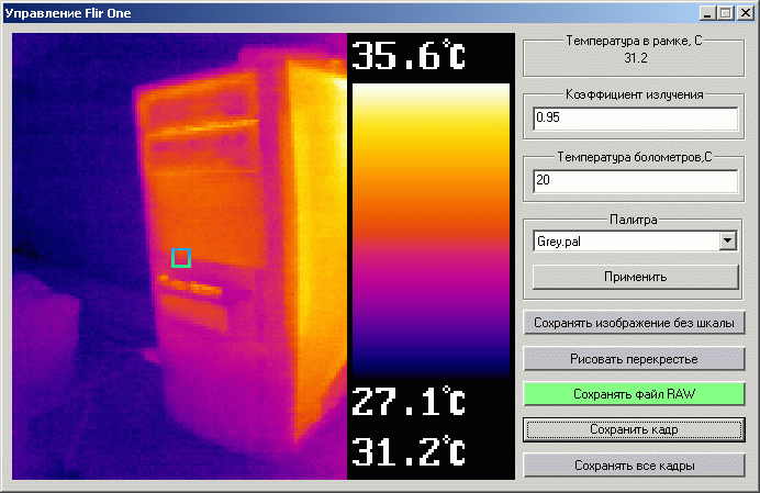
Program for Windows XP.
So, what does this imager represent in terms of sharing with it via USB:
Manufacturer ID: 0x09CB.
Device ID: 0x1996.
The imager has three interfaces:
All of these end points are bulk.
The iAP interface allows you to control the other two interfaces by sending a control command to iAP with the necessary parameters (they are in the attached program and driver files). To obtain a thermal image, it is enough to read and decode data from the end point 0x85 of the Frame interface and not to forget to read the data from the end points 0x81 and 0x83, otherwise the thermal imager may stop data transmission after some time.
The received data looks like this:
What exactly is transmitted throughout the frame, I have not studied; I had enough data from the thermal chamber.
The received data from the thermal camera is an array of 14 bit ADC readings from the bolometric matrix, starting with data block headers for every 80 pixels (one pixel occupies 2 bytes of the unsigned short type). The title looks like this (taken from the documentation for the Lepton 3 thermal imaging module used in FLIR One Gen 2):
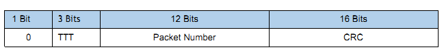
The header of the data block is 80 pixels.
From this header, we are only interested in the CRC code calculated by the polynom specified in the documentation.
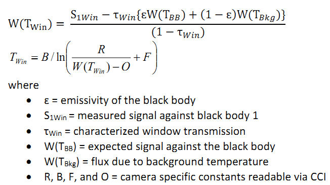
To build a beautiful picture, simply find the maximum and minimum to bring the obtained readings in the range of 0-255 (according to the number of colors of the palette). Actually, this construction of colorful pictures and ends. If there is a desire to calculate the temperature according to the readings, then interesting formulas with a set of coefficients for a specific model of the thermal imager will be required. Fortunately, these coefficients for FLIR One Gen 2 are known.
And the formula according to the “FLIR Lepton with Radiometry Quick start Guide” documentation, is this:
Hmm ... It's good that tomas123 has already attended to such calculations and in his program wrote the function of calculating the temperature of the object. In my rework, it looks like this:
Here TempReflected is the temperature of the bolometric matrix, and Emissivity is the emissivity of the surface being measured. The PlanckR1, PlanckB, PlanckF, PlanckO, and PlanckR2 constants are specific to this thermal imager model.
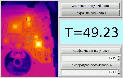
As you can see, my Windows program saves RAW files. For their analysis, I also wrote a separate application. It looks like this:
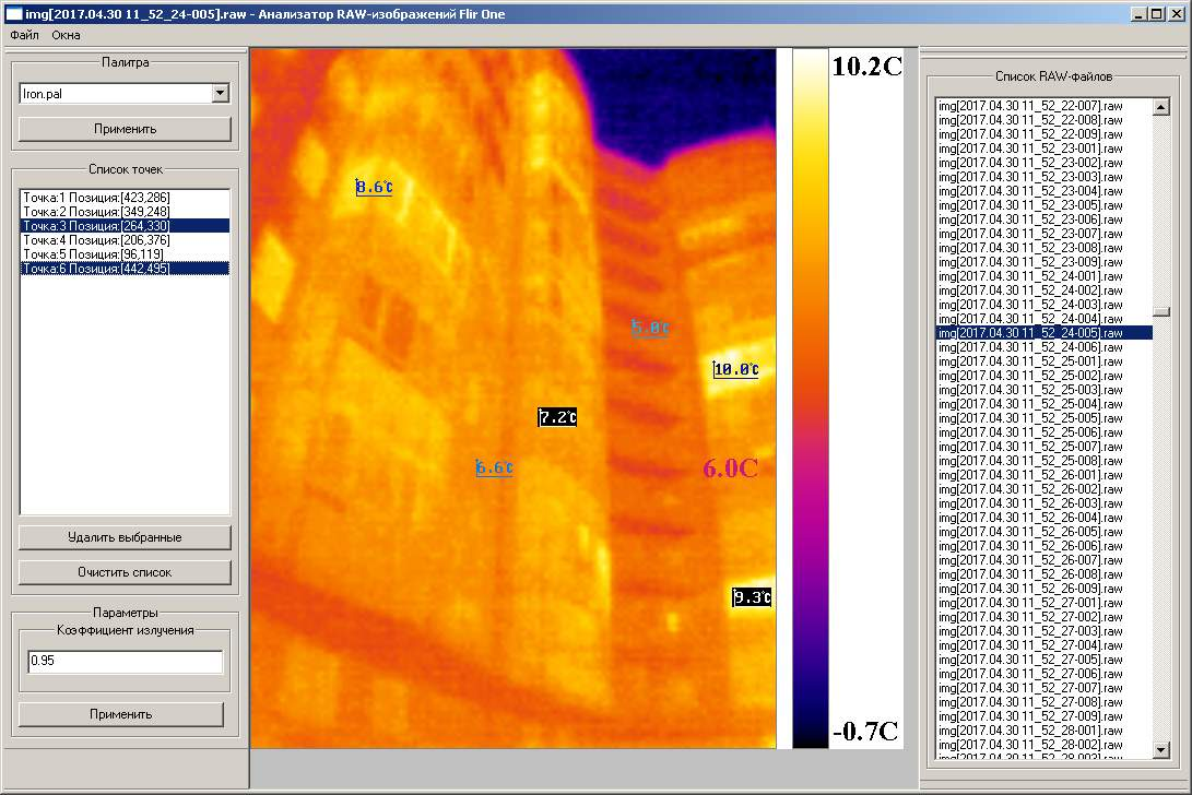
RAW file analyzer for Windows XP.
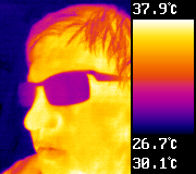
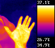
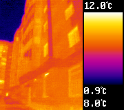
Here are some examples of images taken with this thermal imager from the Windows XP program:
Actually, that's all. The sources and the programs themselves are attached to the links below (I still do not understand how to place them on github).
PS It turned out that from w3bsit3-dns.com without registration, do not download the attached files. Made a link to another resource.
Added links to github:
FlirOneControl
Drivers
Image analysis program
I bought this prefix on ebay three months ago with the hope of connecting to a personal computer via USB and, I must say, my hope came true.
The first thing that needed to be done was to assemble a micro USB cable (mother) to USB (dad). There will be no problems.
Further - more interesting. On the eevblog.com forum , tomas123 opened the USB exchange protocol and wrote its console application for Linux to get a picture of the thermal imaging and conventional camera set-top boxes using libusb. For Linux, the program was not interesting for me, and I tried to write my own program for Windows XP based on the tomas123 program. And this is where the problem arose: libusb for Windows refused to work correctly, producing an error
')
libusb0-dll: err [submit_async] submitting request failed, win error: The parameter is set incorrectly.
After asking a question on the eevblog.com forum, I received the answer that I was the third one who tried unsuccessfully to run this program for Windows using libusb. It also turned out that under Linux, far from all FLIR One distributions work libusb stably - in Ubuntu 10, for example, “pipe error” errors are frequent, and in Mageia 5 there are no such problems. Well, I had to postpone the program for Windows for the future.
The next OS for which I tried to write a program was QNX 6.3. I use this OS at work, but I never wrote a USB driver for it. With the help of the qnx.org.ru forum, I still managed to write something more or less correctly working via USB with FLIR One. Here is the interface of the resulting program:
The program for QNX 6.3.
However, the program is unstable - io-usb very often dies after a couple of minutes in an unequal battle with a thermal imager. Moreover, on some machines, the system does not even notice the connection of the device! It turned out that by switching the operation of the ports in USB 1 to the BIOS, the system still comes to life and begins to detect the device and work with it, albeit with a lower FPS. I suppose that perhaps FLIR One uses an off-the-shelf USB, and this leads to similar problems. But the main thing - the program works and the picture is built.
Then it is time to return to Windows. With the help of this topic, I wrote a driver for Windows XP. After taking off 20 times in the BSOD during the debugging process, the driver came to life, and I received a picture from the thermal imager in the program for Windows XP. Victory! However, everything is again not as rosy as it seemed at first. On some computers (and even from different USB connectors of the same computer) with Windows XP, the driver is simply impossible to install - the system sees FLIR One as a composite USB device and absolutely does not want to divide it into three devices with endings on .iAP,. FileIO and .Frame. The same problem was found in Windows 7, which also did not allow me to install the driver for this OS. How to get around this problem, I still do not know.
Actually, at the moment, on this development of programs for FLIR One and I stopped.
Program for Windows XP.
So, what does this imager represent in terms of sharing with it via USB:
Manufacturer ID: 0x09CB.
Device ID: 0x1996.
The imager has three interfaces:
- iAP with endpoints: 0x00 (read and write), 0x81 (read) and 0x02 (write);
- FileIO with endpoints: 0x00 (read and write), 0x83 (read) and 0x04 (write);
- Frame with endpoints: 0x00 (read and write), 0x85 (read) and 0x06 (write).
All of these end points are bulk.
The iAP interface allows you to control the other two interfaces by sending a control command to iAP with the necessary parameters (they are in the attached program and driver files). To obtain a thermal image, it is enough to read and decode data from the end point 0x85 of the Frame interface and not to forget to read the data from the end points 0x81 and 0x83, otherwise the thermal imager may stop data transmission after some time.
The received data looks like this:
- Four “magic” bytes separating packets from each other: 0xEF, 0xBE, 0x00,0x00;
- A header indicating the sizes of the thermal and normal camera data, the total frame size, and device status data.
- Frame data thermal camera.
- Other data.
What exactly is transmitted throughout the frame, I have not studied; I had enough data from the thermal chamber.
The received data from the thermal camera is an array of 14 bit ADC readings from the bolometric matrix, starting with data block headers for every 80 pixels (one pixel occupies 2 bytes of the unsigned short type). The title looks like this (taken from the documentation for the Lepton 3 thermal imaging module used in FLIR One Gen 2):
The header of the data block is 80 pixels.
From this header, we are only interested in the CRC code calculated by the polynom specified in the documentation.
To build a beautiful picture, simply find the maximum and minimum to bring the obtained readings in the range of 0-255 (according to the number of colors of the palette). Actually, this construction of colorful pictures and ends. If there is a desire to calculate the temperature according to the readings, then interesting formulas with a set of coefficients for a specific model of the thermal imager will be required. Fortunately, these coefficients for FLIR One Gen 2 are known.
And the formula according to the “FLIR Lepton with Radiometry Quick start Guide” documentation, is this:
Hmm ... It's good that tomas123 has already attended to such calculations and in his program wrote the function of calculating the temperature of the object. In my rework, it looks like this:
#define EPS 0.0000000001 double PlanckR1=16528.178; double PlanckB=1427.5; double PlanckF=1.0; double PlanckO=-1307.0; double PlanckR2=0.012258549; double TempReflected=20; double Emissivity=0.95; //--------------------------------------------------------------------------- // //--------------------------------------------------------------------------- bool GetTemperature(unsigned short raw14,double &value) { if (raw14>0x10000) return(false); raw14*=4; double zn=(PlanckR2*(exp(PlanckB/(TempReflected+273.15))-PlanckF)); if (fabs(zn)<EPS) return(false); double RAWrefl=PlanckR1/zn-PlanckO; double RAWobj=(raw14-(1-Emissivity)*RAWrefl)/Emissivity; double lgr=PlanckR1/(PlanckR2*(RAWobj+PlanckO)+PlanckF); if (lgr<=EPS) return(false); value=PlanckB/log(lgr)-273.15; return(true); } Here TempReflected is the temperature of the bolometric matrix, and Emissivity is the emissivity of the surface being measured. The PlanckR1, PlanckB, PlanckF, PlanckO, and PlanckR2 constants are specific to this thermal imager model.
As you can see, my Windows program saves RAW files. For their analysis, I also wrote a separate application. It looks like this:
RAW file analyzer for Windows XP.
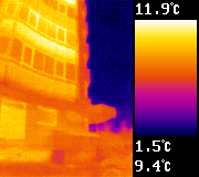
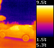
Here are some examples of images taken with this thermal imager from the Windows XP program:
Actually, that's all. The sources and the programs themselves are attached to the links below (I still do not understand how to place them on github).
PS It turned out that from w3bsit3-dns.com without registration, do not download the attached files. Made a link to another resource.
Added links to github:
FlirOneControl
Drivers
Image analysis program
Source: https://habr.com/ru/post/373449/
All Articles