Electric bike Do-it-yourself motor controller
As you already know from past posts, we have a DIY movement in our company. In his spare time, his colleagues are engaged in milling of printed circuit boards at home , make a thermal imager on FLIR Lepton , and also solve family differences with the help of 4 controllers and 2 smart watches . Let's continue the series of fascinating stories! Today I will tell you how to make a controller to a three-phase electric bike with your own hands. The purpose of creating such a controller was:
- Study of the work of a three-phase motor under the control of the controller.
- Most controllers for electric bicycles on the market are Chinese. Although they are relatively cheap (about 2.000 rubles depending on the power), they are an unknown box in which everything is unknown. And immediately there are a lot of questions for her - is it economical to consume and distribute the current, how much power does it have, why does it overheat so much, does current protection work, etc.
At the same time, European high-quality electric bike controllers are on the market. They are equipped with advanced functions, operate at different voltages and currents and can be programmed. They are installed on heavy duty electric bikes. But the price they bite - 10-20 thousand rubles.
In the end, I decided to go my own way: to understand the controller's device, make its prototype, and then try to make the controller better than the Chinese controller. At the moment, the project is in my development only and at the level of the prototype, there is no ready option yet. I will be glad to hear your comments and advice.
Application
Electric bikes use three-phase brushless electric motors with Hall sensors. It should be noted that the use of such three-phase engines is quite extensive:
- Appliances
- Office equipment
- Electric transport
- Industry
Engine unit
To develop a controller, it is necessary to understand the principle of operation of the electric motor itself.

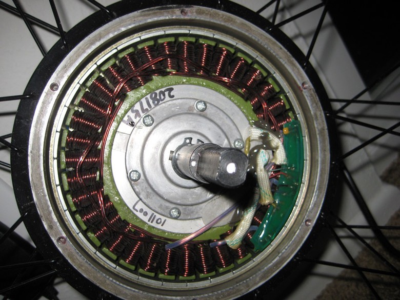
The motor consists of phase windings, magnets and Hall sensors that track the position of the motor shaft.
Structurally, electric motors are divided into two types: inranners and outranners.

Inranners magnetic plates are mounted on the shaft, and the windings are located on the drum (stator), in this case, the shaft is set in motion. In the case of an autranner, the opposite is true: the phase windings are on the shaft, and there are magnetic plates in the drum. This drives the drum.
Since the bicycle wheel is mounted on the frame shaft, the type of outranner is applicable.
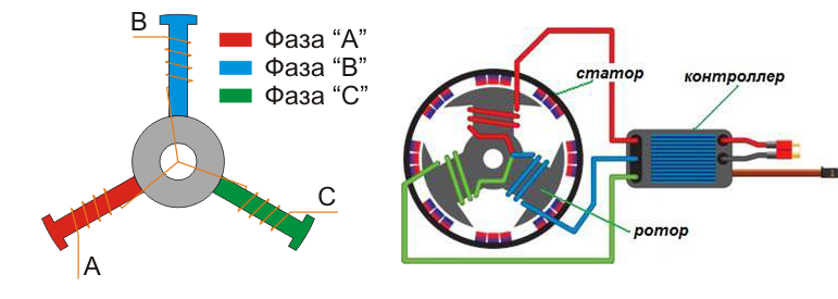
In this picture there are three phases with windings interconnected. In reality, the windings are much larger; they are evenly spaced alternating in phases around the motor circumference. The more windings - the smoother, clearer, more elastic the engine.
Three Hall sensors are installed in the engine. Sensors respond to a magnetic field, thereby determining the position of the rotor relative to the motor stator. Installed at intervals of 60 or 120 electrical degrees. These degrees relate to the electrical phase rotation of the engine. It is necessary to take into account that the more windings in the motor for each phase, the more electric revolutions occur during one physical motor-wheel revolution.

The windings of the three phases in most cases are interconnected according to two schemes: a star and a triangle. In the first case, the current passes from one of the phases to the other, in the second - in all three phases to varying degrees. Sometimes these two connection schemes are combined in one engine, for example, in electric vehicles. When starting and speeding up, the phases are connected by the star: it gives a greater moment at relatively low revolutions; Further, after the speed has been set, a triangle is switched, as a result, the number of revolutions increases when a large torque is no longer needed. In fact, it turns out conditionally automatic transmission of an electric motor.
Work cycle
To set in motion a three-phase motor, it is necessary to consider the cycle of its work for the electric revolution. So, we have three phases - A, B, C. Each of the phases gets positive and negative polarities at a certain point in time. Alternately, in steps, a current is passed from the “plus” of one phase to the “minus” of the other phase. The result is six steps = three phases × two polarities.
A +, A–, B +, B–, C +, C–
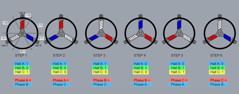
Consider these six steps of the cycle. Suppose that the rotor position is set at the point of the first step, then from the Hall sensors we get the code type 101, where 1 is phase A, 0 is phase B, 1 is phase C. given polarities. As a result, the shaft turns, the sensors read the code of the new shaft position, etc.
The table shows the sensor codes and the change of phase combinations for most electric motors. To reverse the wheel (reverse), it is enough to reverse the polarity signs of the phases in reverse. The principle of operation of the engine is quite simple.
The engine cycle is presented in gif-animation.
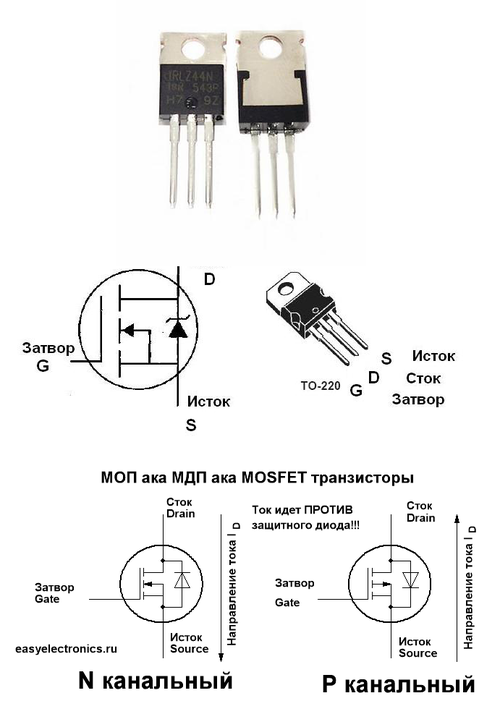
Transistors and H-bridge
But in order to alternately supply current to each of the phases and change their polarity, transistors are needed. We also need the transfer of large currents, high switching speed and clear opening / closing of the gates. In this case, it is more convenient to control the valves by voltage rather than current. Therefore, the optimal field (MOSFET) transistors. Most often they are used in controllers. Very rarely you can find a combined version of the transistors.
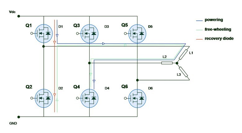
To switch phases with changing their polarities, use the classical H-bridge (H-Bridge) of field-effect transistors.
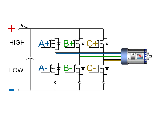
It consists of three pairs of transistors. Each pair is connected to the corresponding phase of the motor winding and provides current with a value (+ or -). The transistors responsible for switching on the phase with a positive value are called high keys. With negative - lower. For each step, a pair of keys is opened: the upper single phase and the lower neighboring phase. As a result, the current passes from one phase to another and sets the motor in motion.
It is clear from the diagram that we cannot turn on the upper and the lower keys simultaneously for the same phase: a short circuit will occur. Therefore, it is very important to quickly switch the upper and lower keys so that a transient does not appear closure. And the better and faster we provide switching, the less we will have losses and heating / overheating of H-bridge transistors.
To start it remains to provide control of the gates of the keys of the H-bridge. To control the H-bridge you need:
- Read the Hall sensors.
- Determine in which position which pair of keys to include.
- Send signals to the corresponding gates of the transistors.
Prototype on Arduino
At hand I had an Arduino UNO, and I decided to put together a controller based on it.
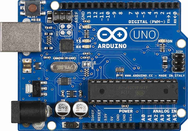
The first thing I gave to Hall sensors was a supply of 5 volts from Arduino (it’s enough for sensors). The signal wires from the sensors connected to the digital pins of Arduino, writing a simple program for reading and processing signals from the sensors.
// - const int TRAplus = 8; const int TRAminus = 9; const int TRBplus = 10; const int TRBminus = 11; const int TRCplus = 12; const int TRCminus = 13; // const int HallA = 3; const int HallB = 1; const int HallC = 0; boolean vala; boolean valb; boolean valc; boolean pvala; boolean pvalb; boolean pvalc; int pHall; int turns; void setup() { // pinMode(TRAplus, OUTPUT); pinMode(TRAminus, OUTPUT); pinMode(TRBplus, OUTPUT); pinMode(TRBminus, OUTPUT); pinMode(TRCplus, OUTPUT); pinMode(TRCminus, OUTPUT); // Serial.begin(9600); } void loop() { // val vala = digitalRead(HallA); valb = digitalRead(HallB); valc = digitalRead(HallC); // . if(vala && !pvala) { if(pHall == HallC) // HallB turns++; pHall = HallA; } if(valb && !pvalb) { if(pHall == HallA) // HallC turns++; pHall = HallB; } if(valc && !pvalc) { if(pHall == HallB) // HallA turns++; pHall = HallC; } digitalWrite(TRAplus, (vala && !valb) ? HIGH : LOW); // vala==HIGH valb==LOW, HIGH, LOW digitalWrite(TRAminus, (valb && !vala) ? HIGH : LOW); digitalWrite(TRBplus, (valb && !valc) ? HIGH : LOW); digitalWrite(TRBminus, (valc && !valb) ? HIGH : LOW); digitalWrite(TRCplus, (valc && !vala) ? HIGH : LOW); digitalWrite(TRCminus, (vala && !valc) ? HIGH : LOW); pvala = vala; pvalb = valb; pvalc = valc; Serial.print(vala); Serial.print(valb); Serial.println(valc); //Serial.println(turns/3); } Then he assembled an N-bridge from field NPN transistors. He brought to the bridge an independent power supply at 12 volts. But when debugging, to make sure I was working, I connected six pins 5V directly from Arduino to the gates of the H-bridge. Most field-effect transistors have a gate operating at 20 volts. So it is impossible to do, because the N-bridge will work poorly and overheat. But for short-term tests it will go. Somehow, with strong overheating and scary sounds, vibrations and jolts the wheel spun slowly. A start.
Bridge drivers
Next came the work on the voltage of 20 volts to control the valves. To do this, there are bridge drivers of transistors, they provide stable pulses of 20 volts to the gate and high response speed. At first I had popular drivers for low-power L293D motors.
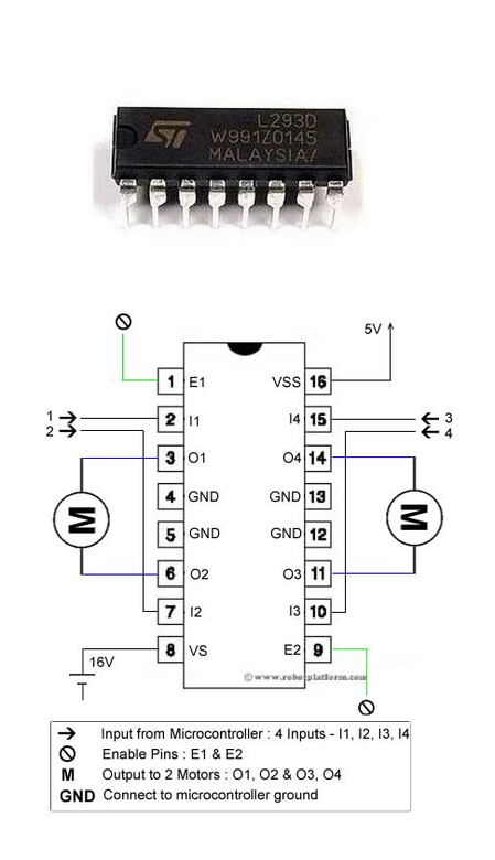
To control the valves it is enough, besides, they are very simple to use. One such driver can provide power for two pairs of keys. So I took two pieces of L293D. I assembled the controller with these drivers, and the wheel started spinning much smoother, there were less extraneous sounds, the heating of the transistors decreased. But with increasing speed, synchronization with the controller disappeared, a strange sound appeared, the wheel jerked, vibrated and stopped completely.
At the same time, I came across two options for bridge drivers:
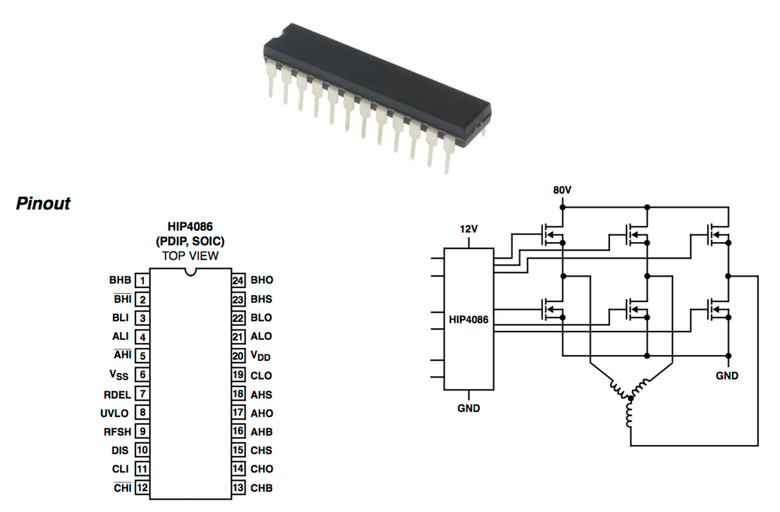
- HIP4086
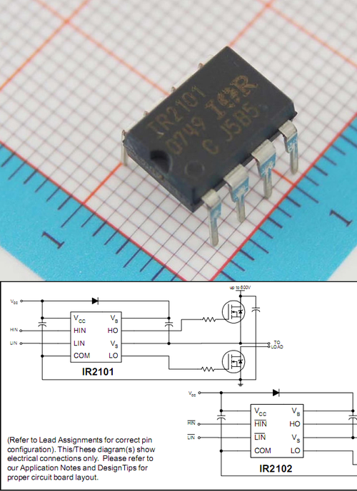
- IR2101
As for the HIP4086, this is a complete bridge driver designed for a three-phase electric motor. It seemed to me somewhat confused, and my attempts to use it in the controller were not crowned with success: it never worked for me. In-depth understanding of the reasons did not.
And I took the IR2101 - half-bridge driver, which provides the operation of the lower and upper keys for one phase. It is easy to guess that you need three such drivers. By the way, the driver is very easy to use, its connection is painless and easy. It turned out this scheme:
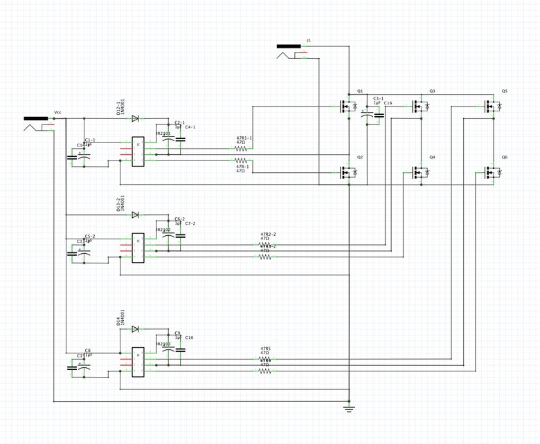
Printed circuit board
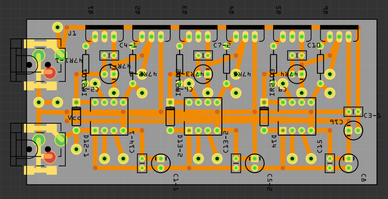
And the finished result
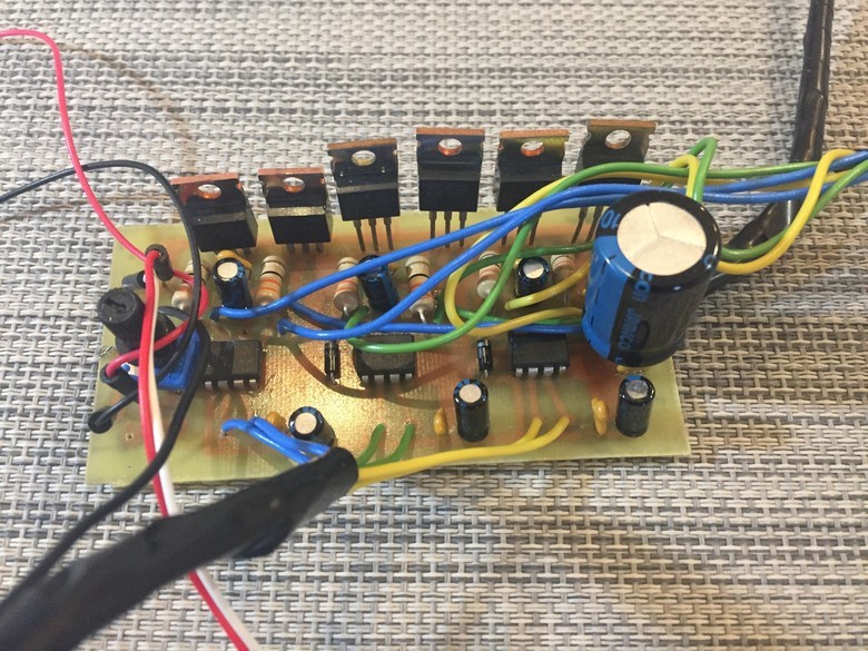
I assembled a controller with this driver and started the engine. The situation with the work of the motor has not changed dramatically, the symptoms remain the same as in the case of the driver L293D.
Hardware interrupt
And then I realized what was the matter: Arduino does not have time to process the Hall sensor readings! Therefore, it was necessary to use Arduino pins with a hardware interrupt. Since Arduino DNA has only two such pins, and under the sensors you need three pins, you need to take Arduino Leonardo or Iskra Neo, where there are four such pins.
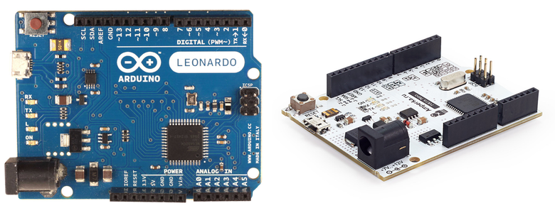
Rewriting the program under the interrupt and connecting Iskra Neo instead of DNA, I repeated the test.
// - const int TAH = 8; //T — , — (), — const int TAL = 9; //T — , — (), L — const int TBH = 10; //T — , B — (), H — const int TBL = 11; //T — , B — (), L — const int TCH = 12; //T — , C — (), H — const int TCL = 13; //T — , C — (), L — //------------------------------------------------------------------------------------------------ // int HallA = 3; // 1 ( ) int HallB = 1; // 2 ( ) int HallC = 0; // 3 ( ) //------------------------------------------------------------------------------------------------ volatile boolean vala; volatile boolean valb; volatile boolean valc; //------------------------------------------------------------------------------------------------ void setup() { // pinMode(TAH, OUTPUT); pinMode(TAL, OUTPUT); pinMode(TBH, OUTPUT); pinMode(TBL, OUTPUT); pinMode(TCH, OUTPUT); pinMode(TCL, OUTPUT); // vala = digitalRead(HallA); valb = digitalRead(HallB); valc = digitalRead(HallC); // attachInterrupt (digitalPinToInterrupt(HallA), changeA, CHANGE); attachInterrupt (digitalPinToInterrupt(HallB), changeB, CHANGE); attachInterrupt (digitalPinToInterrupt(HallC), changeC, CHANGE); //LOW , LOW //CHANGE LOW HIGH, //RISING LOW HIGH //FALLING HIGH LOW } void Fases() { digitalWrite(TAH, (vala && !valb) ? HIGH : LOW); digitalWrite(TAL, (valb && !vala) ? HIGH : LOW); digitalWrite(TBH, (valb && !valc) ? HIGH : LOW); digitalWrite(TBL, (valc && !valb) ? HIGH : LOW); digitalWrite(TCH, (valc && !vala) ? HIGH : LOW); digitalWrite(TCL, (vala && !valc) ? HIGH : LOW); void changeA() { vala = digitalRead(HallA); Fases(); } void changeB() { valb = digitalRead(HallB); Fases(); } void changeC() { valc = digitalRead(HallC); Fases(); } void loop() { } The wheel finally worked clearly, without vibrations, noise, it was great to gain momentum without desynchronization. The prototype was viable. But this is not a full-fledged controller, since it did not have a strapping with protections and the provision of high-quality PWM signal.
MC33035 based prototype
In parallel with the development of the controller at Arduino, I considered alternatives to the logical part of the controller. And that led me to the MC33035 chip. This is an old development from Motorola, now it is released by ON Semiconductor. Designed specifically for powerful three-phase motors.
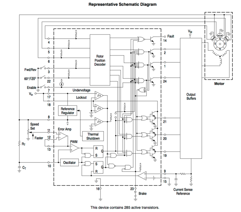
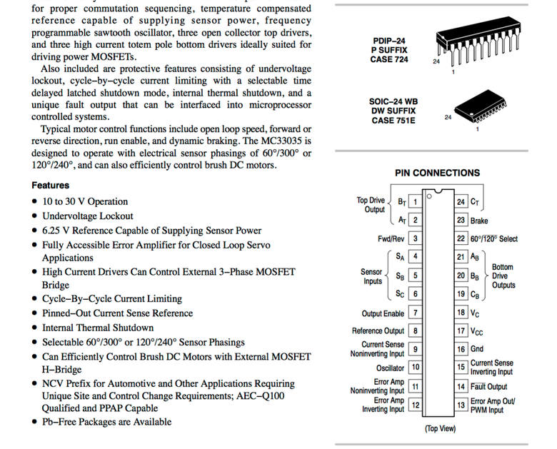
This chip:
- Responsible for the entire logical part of the controller
- Reads from Hall sensors
- Defines the position of the shaft
- Gives signals for N-bridge gates to their drivers.
- Has the ability to connect an error indicator, overheating
- Processes and transmits PWM signal (PWM)
- Carries the reverse (reverse wheel)
In short, the chip contains everything you need to control the motor. Its cost is very low: on Aliexpress - about 50 rubles. To build a full-fledged controller based on it, you need an MC33035 microcircuit, half-bridge drivers and an N-bridge of field-effect transistors. I also assembled the controller on this chip. It works perfectly, stably, the wheel is spinning as it should at various revolutions. But the functionality of the microcircuit is limited, if it is necessary to tinker with various functions, display the speed, odometer, battery consumption, then again there is a need to additionally connect Arduino or something similar.
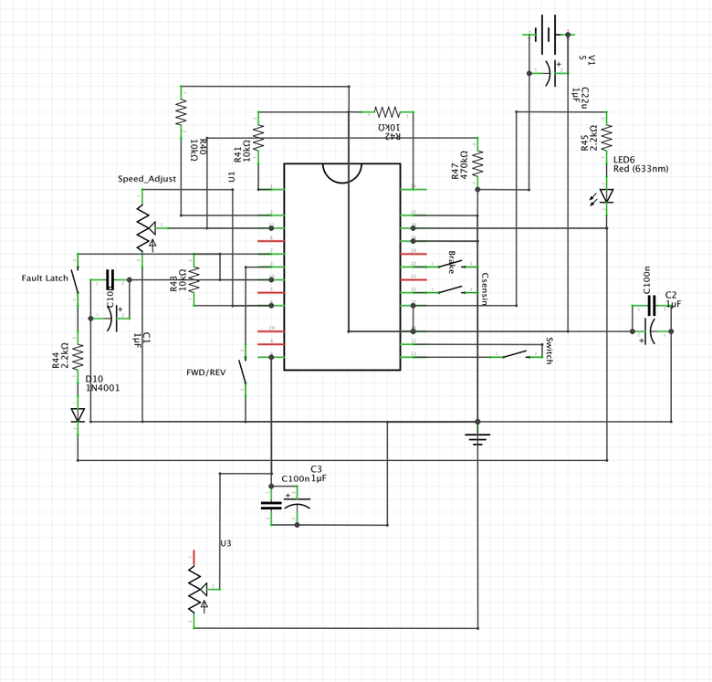
Circuit with MC33035
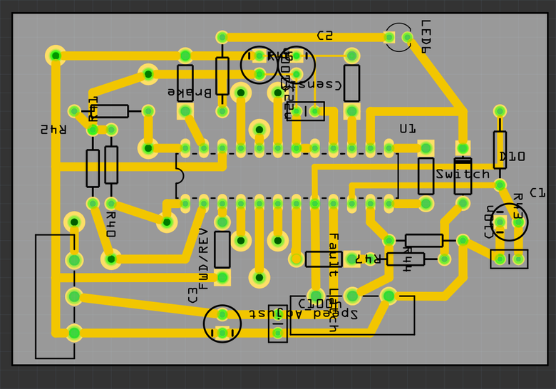
Printed circuit board
Ready option
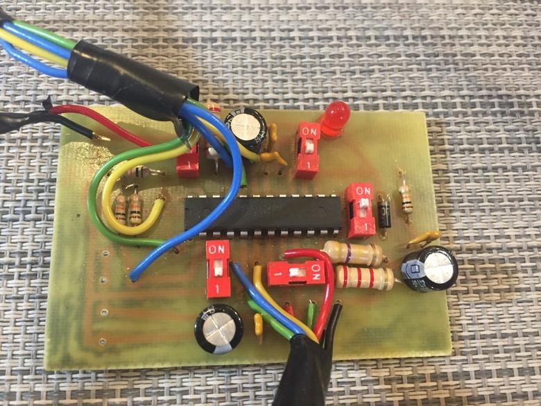
Total
The main advantage of the MC33035 based controller is its ease of use. Just buy a chip, collect the H-bridge, solder everything on the board with a small strapping - and the controller is ready. If you just need to start the engine with a PWM signal and control it, the best option.
Arduino-based controller - the option is more difficult, you need to write logic, to provide additional protection for the controller. But for experiments, prototypes, additional functionality, the use of various engine operating modes is a suitable option. Therefore, I decided to postpone MC33035 for the time being and continue working with Arduino.
Future plans for the controller
Continuing work on the controller, I plan to do the following:
- IGBT transistors for H-bridge instead of field-effect transistors.
- Strapping with protection for current, overheating, etc.
- Full cruise control with the ability to set the desired speed.
- Flow meter When the required distance is set, and the controller, based on this value and battery charge, discharges the battery discharge throughout the route so that there is enough charge.
')
Source: https://habr.com/ru/post/373397/
All Articles